CNC Bárcenas · SW1325V-ATC
CNC Milling — Operation and Safety
Base documentation by: FabLab Ponferrada ↗️
Machine specifications
| Parameter | Value |
|---|---|
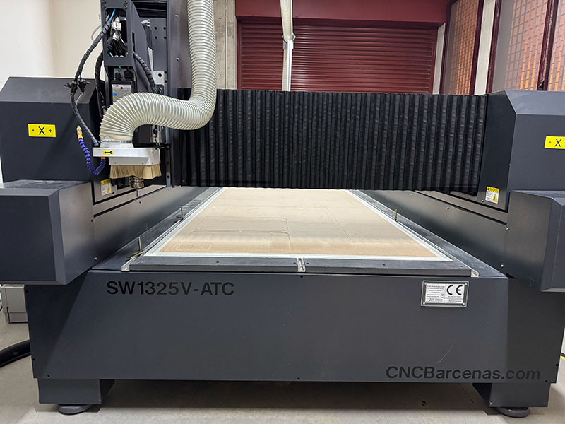
| Model | Bárcenas SW1325V-ATC |
| Working area | 1300 × 2500 mm |
| Approximate dimensions | 2300 × 3850 × 2200 mm |
| Bridge height | 250 mm |
| Spindle power | 9 kW |
| Spindle cooling | Air |
| Maximum working speed | 166 mm/s |
| Repeatability | 0.025 mm |
| Fixturing system | 4.5 kW vacuum pump |
| Automatic tool changer | Up to 8 tools |
| Approximate maximum thickness | ~40 mm (depending on the tool) |
| Software | MDR CNC Router + Cut2D |
| Compatible files | STL, DXF, G-code and others |
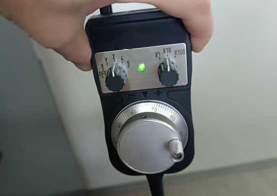
| Control | Computer + MPG controller |
| Approximate weight | 1200 kg |
The actual machining capacity depends on the material, the tool used, and the cutting parameters.
Compatible materials
- Solid wood
- Plywood
- DM / MDF
- Acrylic
- PP and other technical plastics
- Technical foams
- Bakelite
- Brass
- Non-ferrous metals
Machine operation
Power on and homing
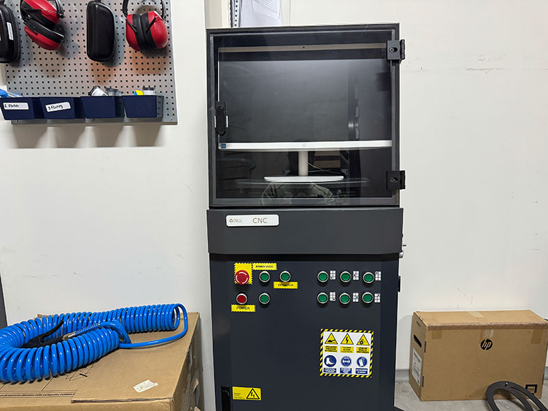
- Turn on the CNC router using the POWER button on the front panel.
- Turn on the integrated computer.
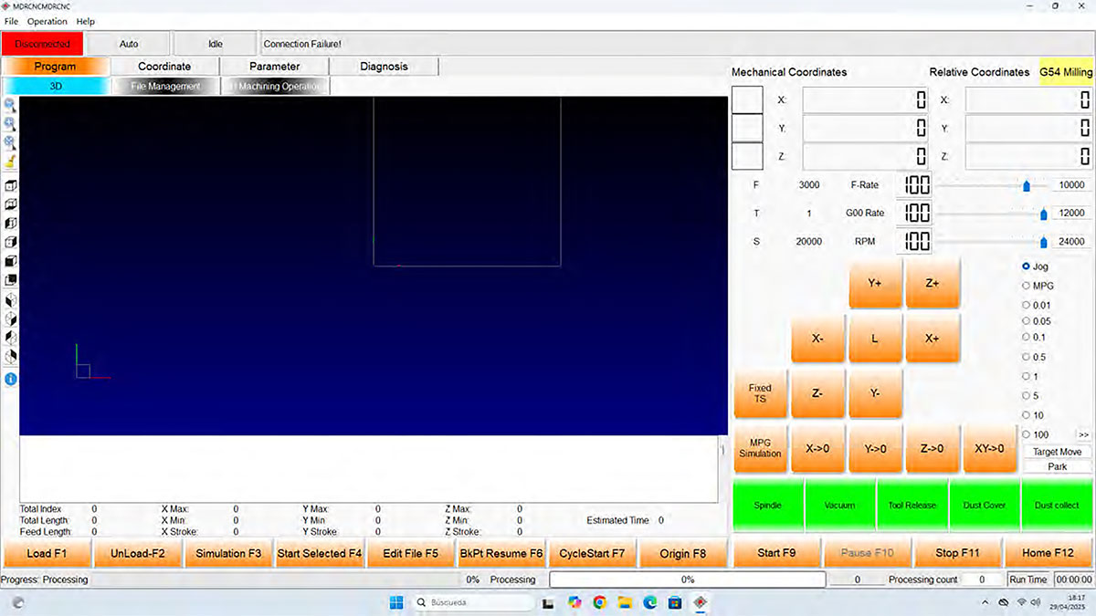
- Open the MDR CNC Router software.
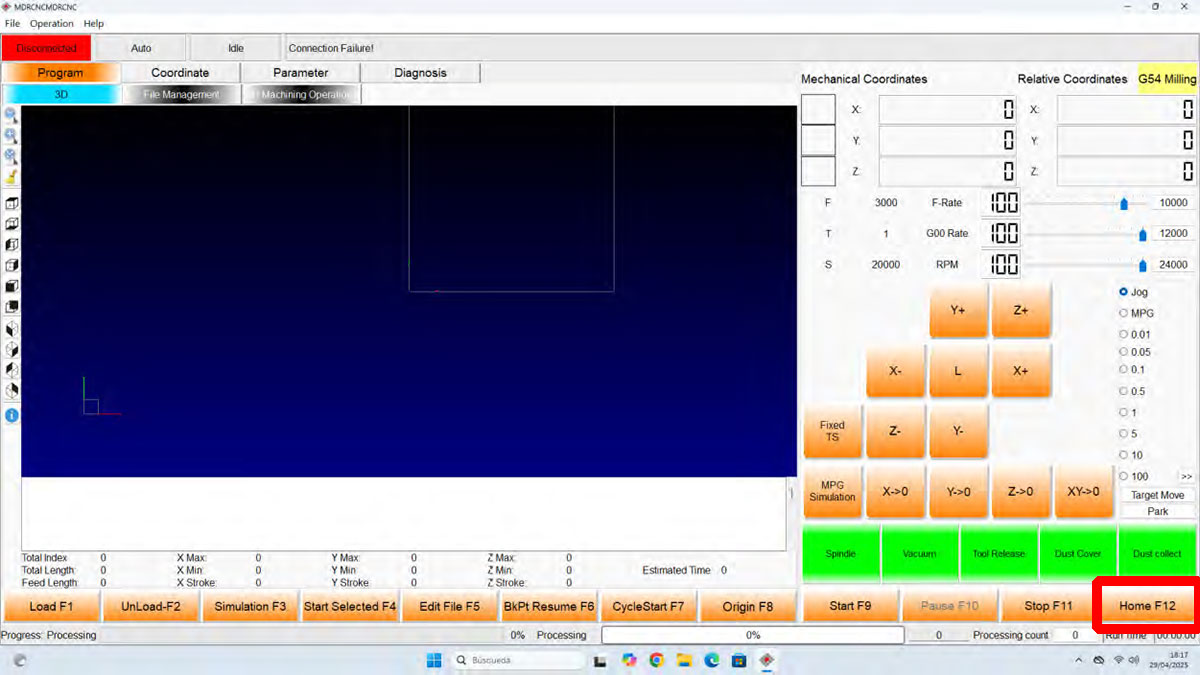
- Run the HOME process, which is mandatory before starting any job.
During homing, the machine moves to its mechanical origin: the X axis moves to the left, the Y axis to the beginning of the table, and the Z axis moves up to its initial position.

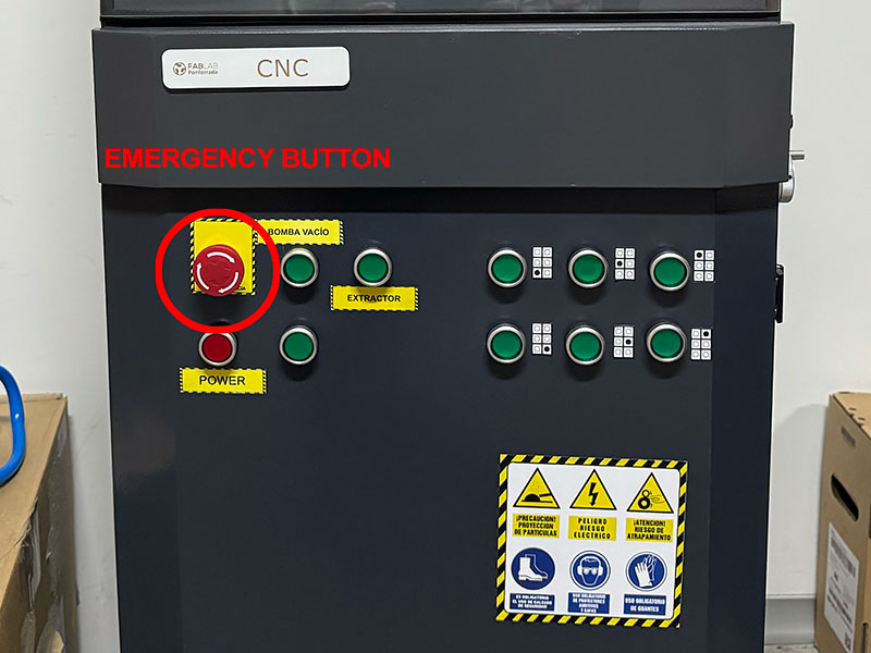
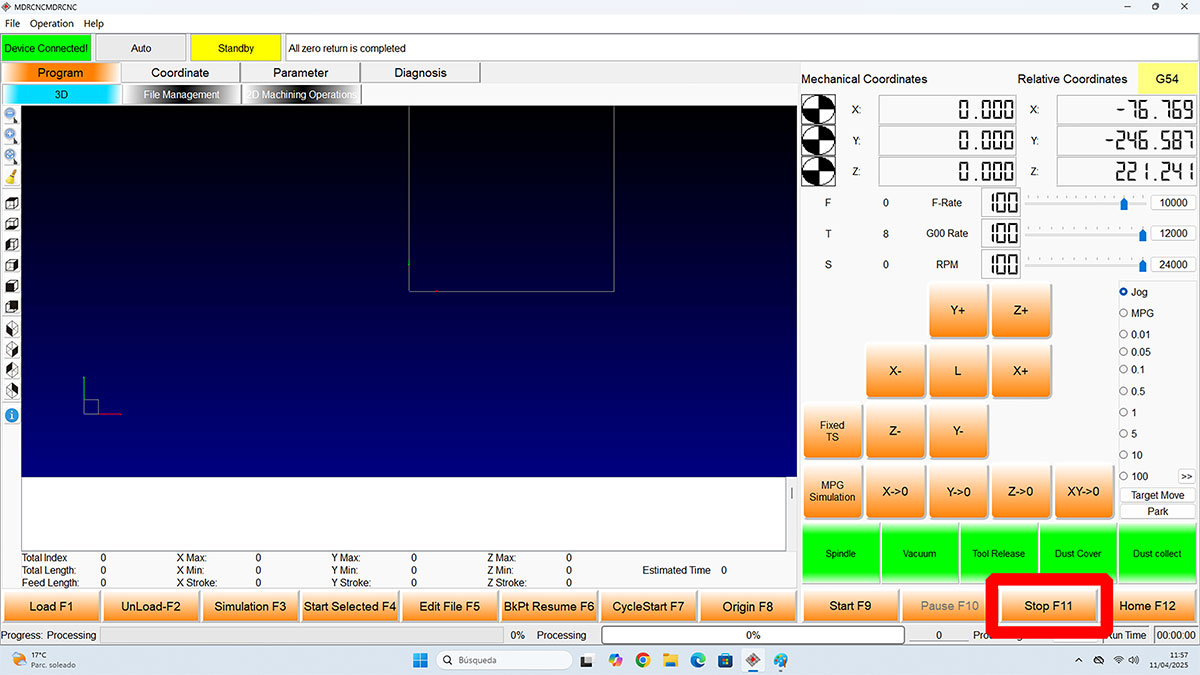
STOP emergency & STOP software button
It is very important to know where the buttons are to stop the machine in case something goes wrong or in an emergency.
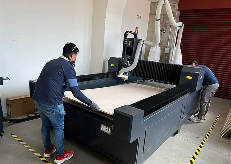
Material placement and fixturing
- Place the material on the worktable.
- Use protective gloves.
- Fix it using the vacuum system or mechanical clamps.
- Check that the material is flat and stable.
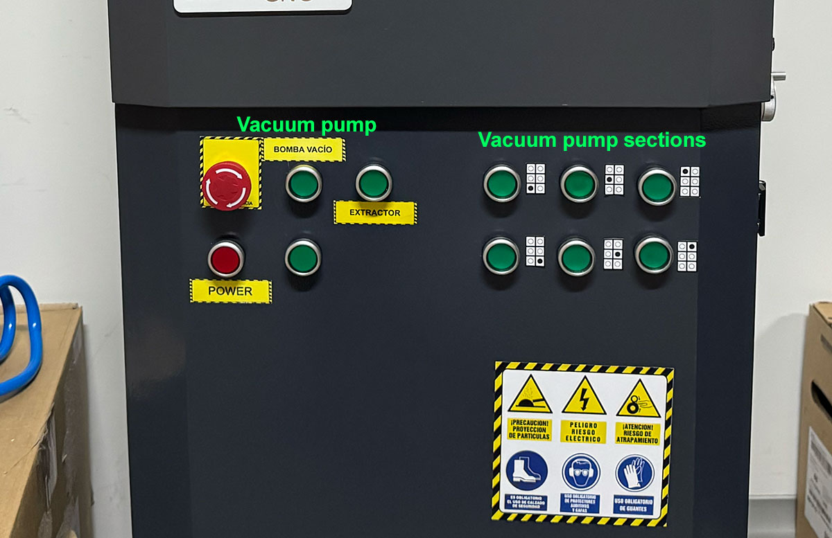
- Activate the extraction system and the required vacuum zone.
Poor fixturing can cause vibrations, material displacement, or machining errors.
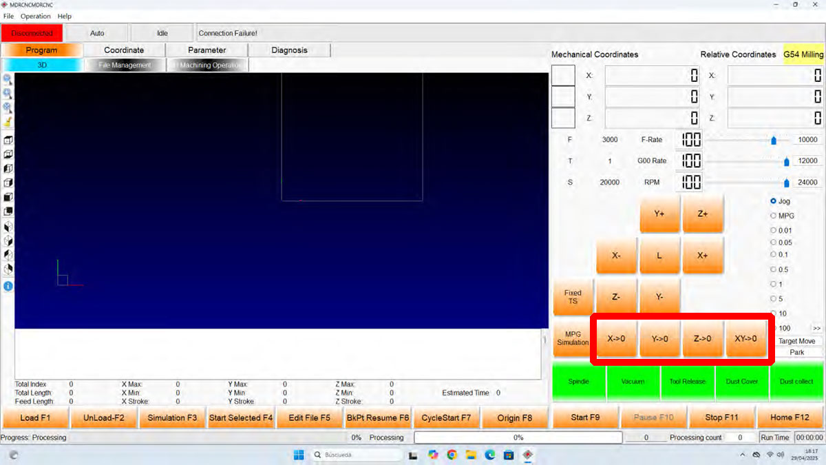
Define the work origin
- Move the spindle to the desired starting position.
- Set the XY origin using the XY0 button.
- Adjust the tool to the material surface.
- Set the Z origin using the Z0 button.
It is recommended to activate the vacuum system before measuring the Z axis in order to avoid errors in the reference height.
Send and run the job
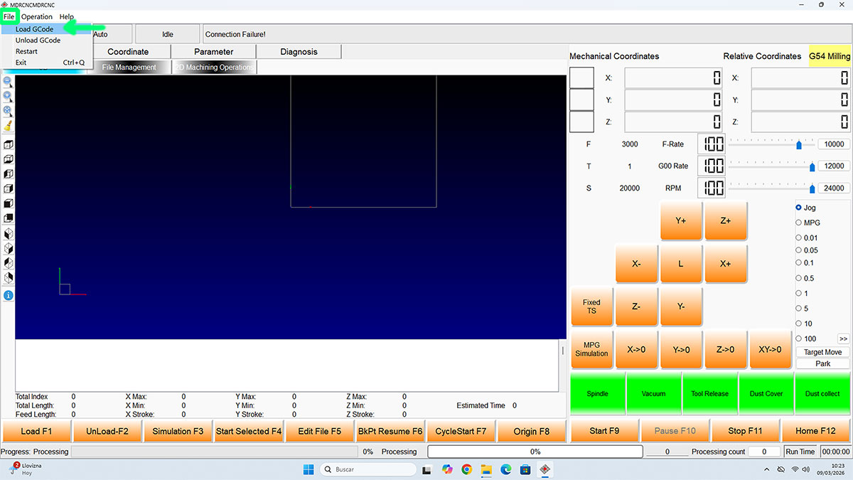
- Load the G-code file generated from Cut2D into MDR CNC Router.
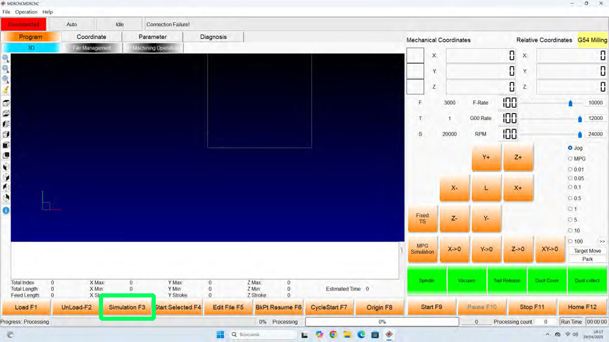
- Review the machining simulation by clicking the "Simulation" button.
- Activate the vacuum pump and the zones that are needed.
- Check that the material is properly fixed and ready to be machined.
- Verify the XY and Z origins.
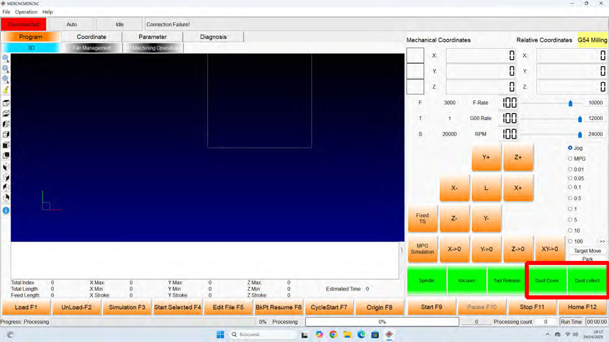
- Activate the "Dust cover" and "Dust Collect" buttons to lower the brush and start suction.
- Turn on the "Extractor" switch.
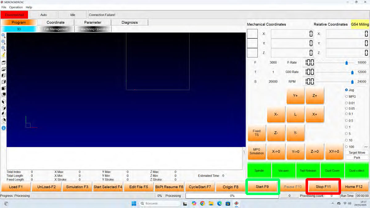
- Start the job with START or by pressing F9.
- If necessary, press the STOP button or use the emergency STOP switch.
During machining, the process can be paused with PAUSE, stopped with STOP, and both the feed rate and the spindle RPM can be adjusted if necessary.
Cut2D workflow (Lab's software)
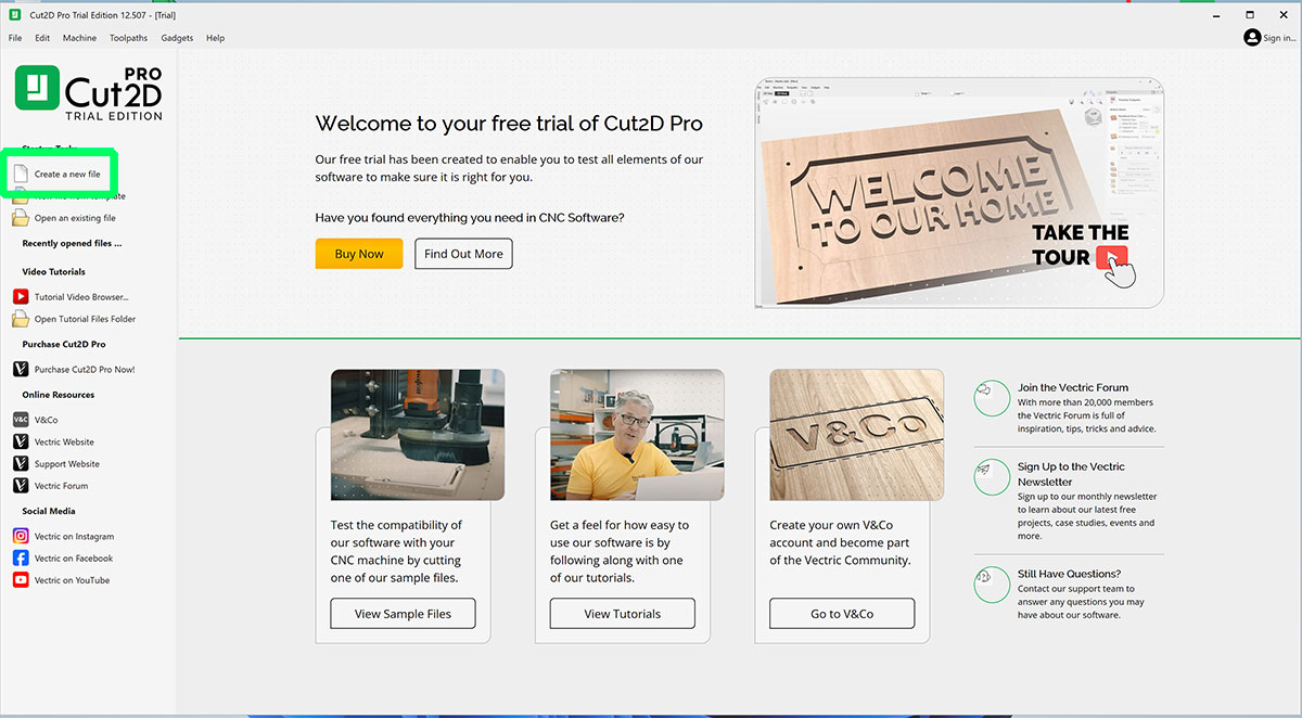
Initial material setup
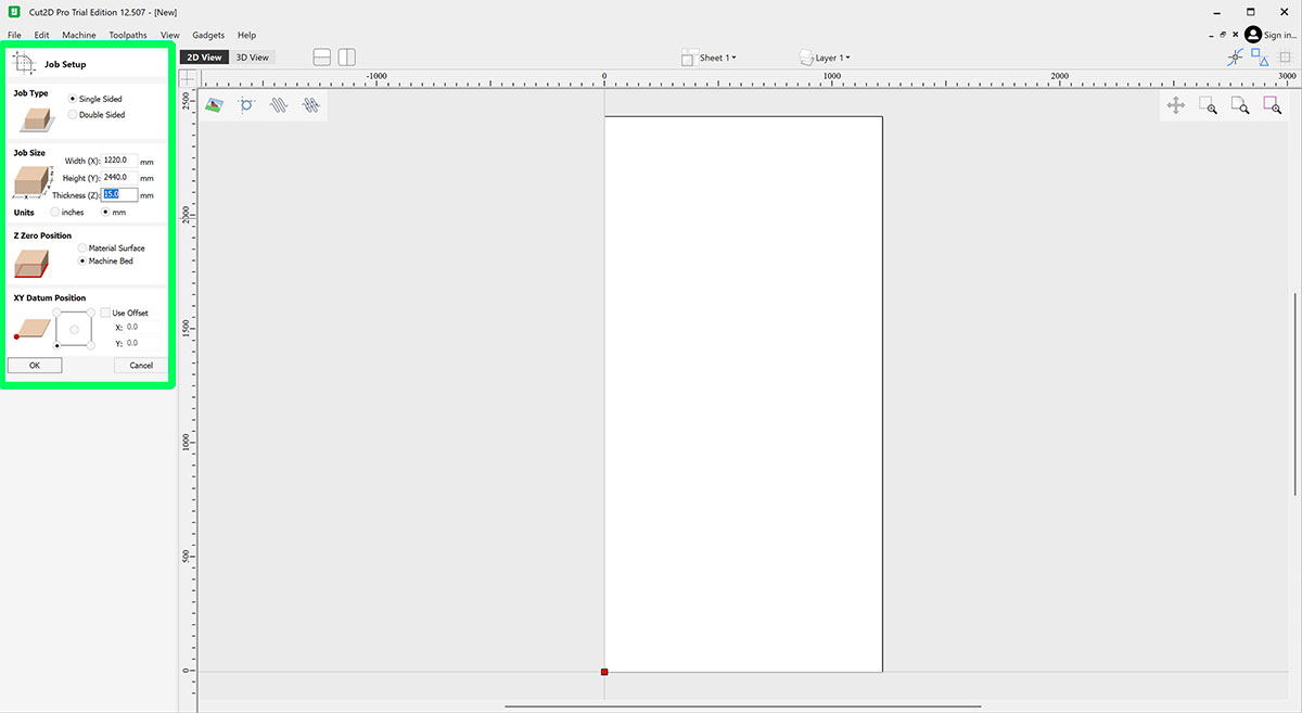
When creating a new document in Cut2D, the first step is to define the material size correctly:
- Material width (X axis)
- Material length (Y axis)
- Material thickness (Z axis)
For this machine, we will normally work with:
- XY origin: bottom / left
- Z origin: material surface
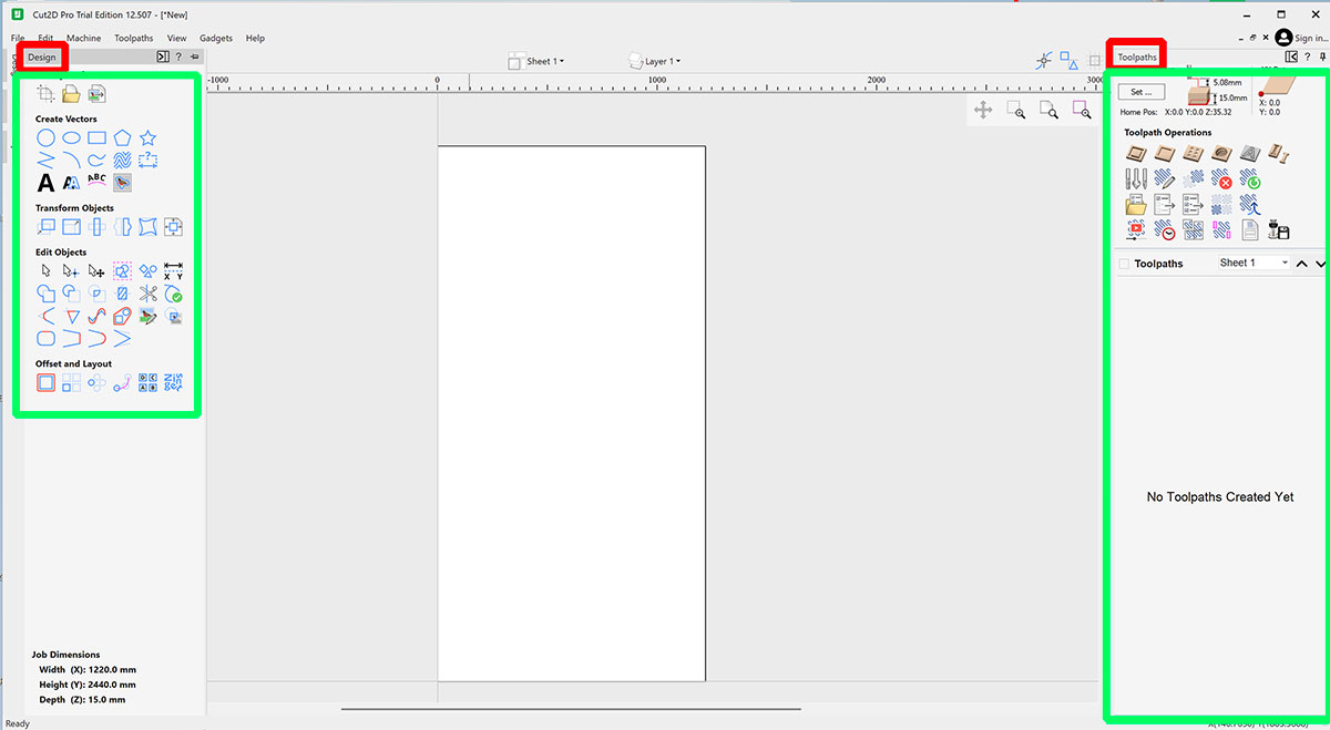
General interface
The Cut2D interface is organized into three main areas:
- Left side: drawing, importing, and vector editing tools.
- Center area: workspace where the designs are placed and adjusted.
- Right side: toolpath creation.
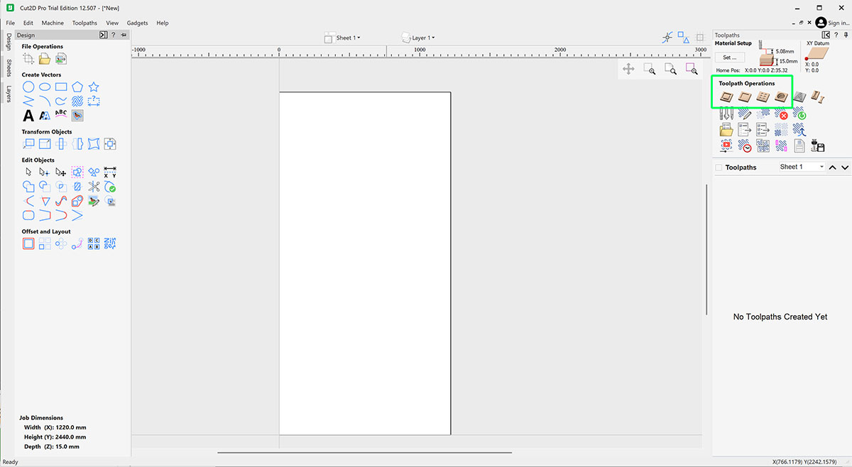
Toolpath types
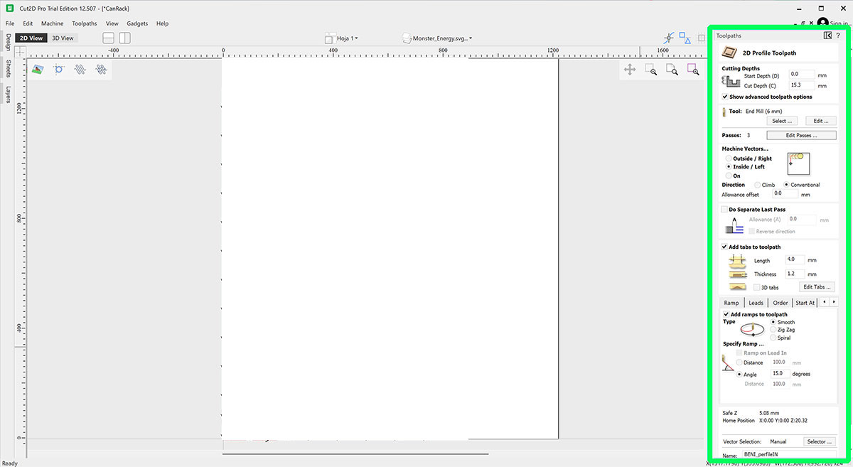
- Profile: cut following the contour of a vector.
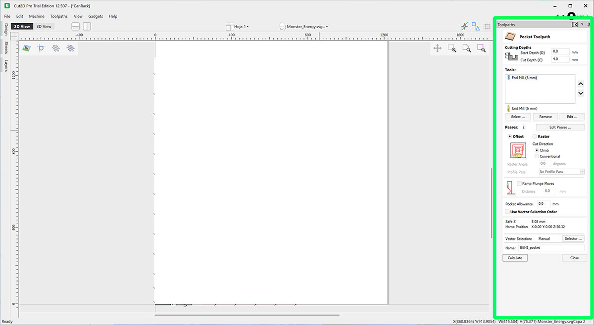
- Pocket: remove the inside of a shape.
- Drilling: create holes at specific points.
- Engraving: shallow or decorative machining.
Simulation and export
Before exporting the file, it is always a good idea to run the simulation to visually review the machining, check depths, operation order, and detect errors.
Tools and end mills
In a CNC router, the cutting tool is one of the most important factors for achieving clean, safe, and efficient machining. Choosing the correct end mill directly affects the finish quality, working speed, and tool life.
The tools used in this machine are shank end mills, designed to work at high spindle speeds and evacuate the chips generated during machining.
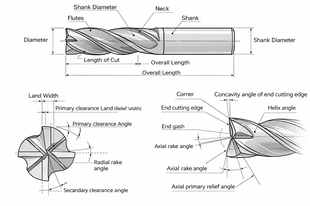
Parts of an end mill
A typical end mill is made up of several parts:
- Shank: cylindrical part that is inserted into the spindle collet.
- Neck: transition area between the shank and the cutting area.
- Cutting area: active part that comes into contact with the material.
- Flutes: channels that evacuate chips and help reduce heat buildup.
Tool material
| Material | Description | Hardness | Cost | Typical uses |
|---|---|---|---|---|
| HSS (High Speed Steel) |
Traditional high-speed steel. Flexible and impact resistant. Lower wear resistance. |
Low | Low |
Wood Plastics Light machining |
| HSS-Co (Cobalt Steel) |
HSS alloyed with cobalt. Higher heat resistance. Improved tool life. |
Medium | Medium |
Steels Stainless steel More demanding machining |
| Solid Carbide |
Solid tungsten carbide. Very hard and precise. Allows higher cutting speeds. |
High | Medium–high |
CNC routers Hard woods Plastics Aluminum |
| Coated Carbide |
Carbide with coatings (TiN, TiAlN, DLC…). Reduces friction and wear. |
Very high | High |
Industrial machining Steels Aluminum Abrasive materials |
| PCD (Polycrystalline Diamond) |
Polycrystalline diamond. Extremely hard. Excellent wear resistance. |
Extreme | Very high |
Carbon fiber Fiberglass Composites Graphite |
| CBN (Cubic Boron Nitride) |
Ultra-hard material. Very high thermal resistance. Designed for very hard metals. |
Extreme | Very high |
Hardened steels Superalloys Precision machining |
Number of flutes
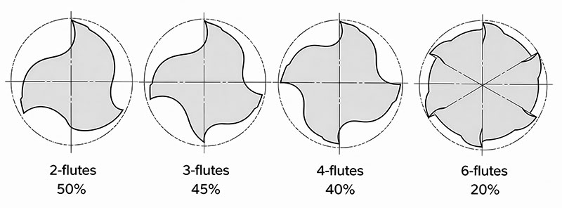
| 2-flutes | 3-flutes | 4-flutes | 6-flutes | |
|---|---|---|---|---|
| Advantage |
Chip disposability is excellent. Suitable for sinking. Low cutting resistance. |
Chip disposability is excellent. Suitable for sinking. |
High rigidity |
High rigidity. Superior cutting edge durability. |
| Fault | Low rigidity | Diameter is not easily measured. | Chip disposability is poor. | Chip disposability is poor. |
| Usage |
Slotting, side milling, sinking etc. Wide range of use. |
Slotting, side milling Heavy cutting, finishing |
Shallow slotting, side milling Finishing |
High hardness material Shallow slotting, side milling |
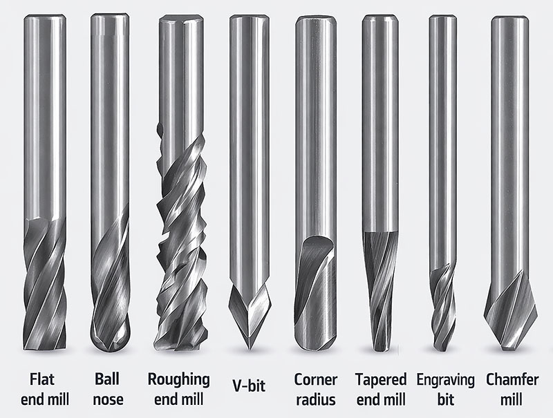
Most common end mill types
| Type | Main characteristics | Main uses |
|---|---|---|
| Flat end mill |
Flat cutting tip. Produces sharp edges and flat-bottom pockets. Very versatile for general machining. |
Profile cutting. Pocketing. General 2D machining. Slots and contours. |
| Ball nose |
Rounded tip. Better for smooth curved surfaces. Leaves a softer finish on 3D shapes. |
3D machining. Reliefs and organic surfaces. Finishing curved geometries. |
| Roughing end mill |
Serrated cutting edges. Designed to remove large amounts of material quickly. Generates higher chip evacuation. |
Fast material removal. Roughing passes before finishing. Heavy cutting operations. |
| V-bit |
V-shaped tip. Available in different angles. Good for fine detail and variable-width engraving. |
Engraving. Chamfers. Decorative details. V-carving. |
| Corner radius |
Flat end with rounded corners. Stronger than a standard flat end mill. Reduces corner chipping. |
Finishing operations. Pocketing with smoother internal corners. General machining with improved tool life. |
| Tapered end mill |
Conical profile with cutting tip. More rigid than a straight small-diameter tool. Good for deep or narrow areas. |
3D carving. Deep detail work. Molds and relief machining. |
| Engraving bit |
Fine pointed tip. Designed for precise shallow cuts. Good for sharp lines and text. |
Fine engraving. Lettering. PCB marking. Small decorative details. |
| Chamfer mill |
Angled cutting profile. Made specifically for beveling edges. Can also be used for deburring. |
Chamfers. Edge finishing. Deburring. Preparation before assembly. |
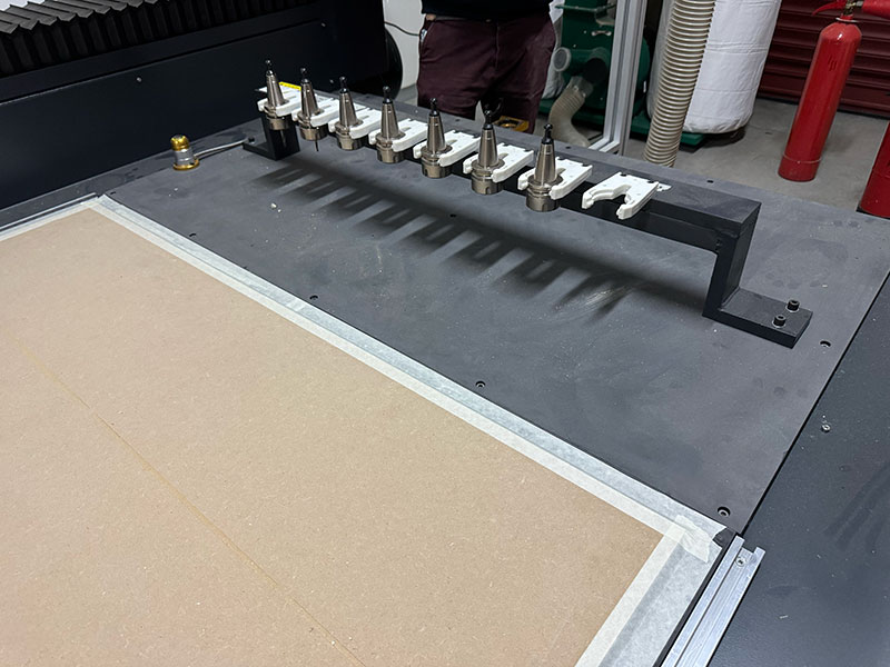
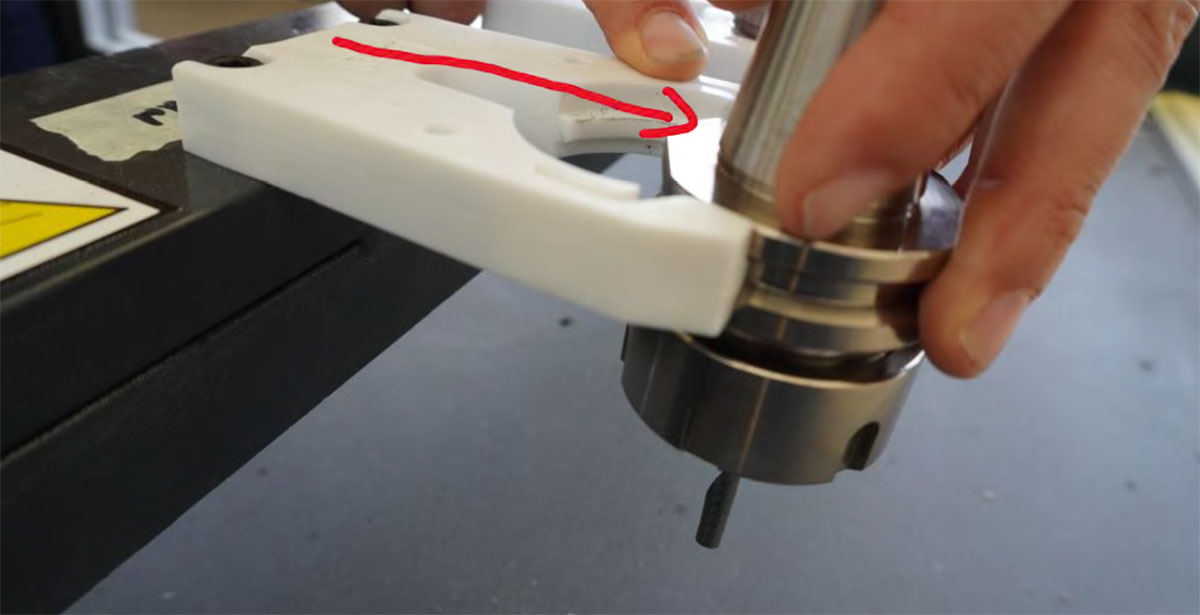
Tool change and ATC
The CNC Bárcenas SW1325V features an ATC (Automatic Tool Changer) system with up to 8 positions. Each tool must:
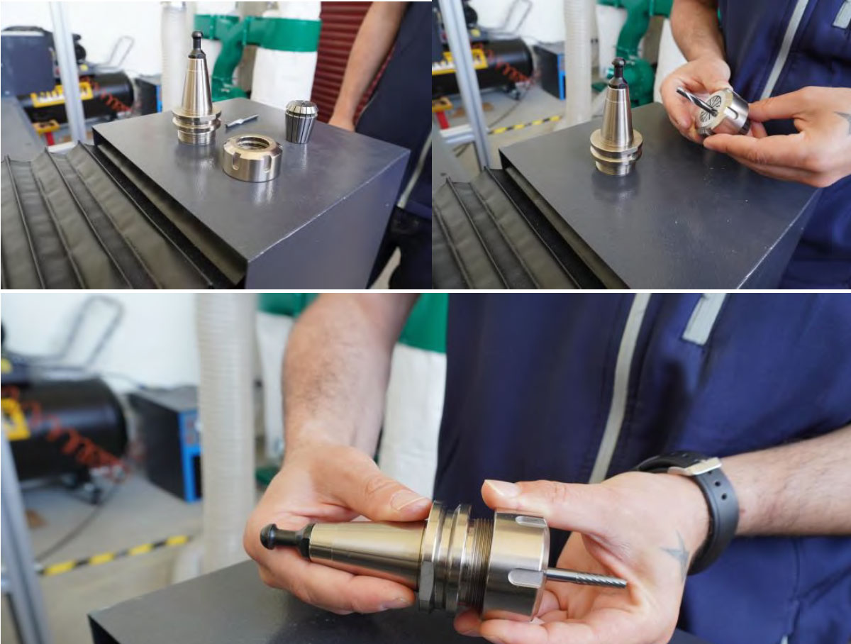
- Be correctly mounted in its ER collet.
- Be placed in the correct position in the tool rack.
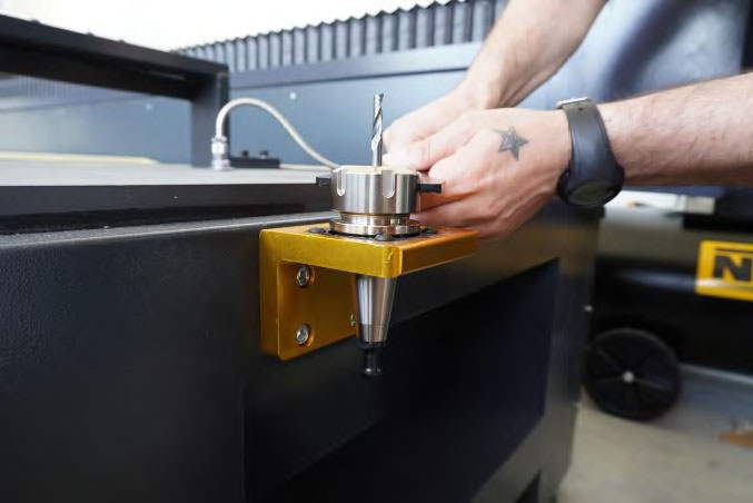
- Be calibrated using the tool measurement system.
Machining parameters
Unlike the laser cutter, where we mainly talk about power and speed, in CNC milling the machining behavior depends on several combined parameters.
The most important ones are:
- RPM (spindle rotation speed)
- Feed rate
- Depth of cut
- Step-over
Adjusting these parameters correctly is essential to avoid:
- Tool breakage
- Poor cut quality
- Overheating
- Vibration during machining
RPM (spindle speed)
The spindle speed indicates how many revolutions per minute the tool performs. On this machine, the spindle can reach approximately 24000 RPM. A speed that is too low may cause an irregular cut, while an excessive speed may overheat the tool.
Feed rate
The feed rate indicates how fast the tool moves over the material during machining. It is normally expressed in mm/min.
A feed rate that is too high can cause:
- Tool breakage
- Vibration
- Loss of precision
A feed rate that is too low can generate excessive friction and burn the material.
Depth of cut
The depth of cut determines how much material the tool removes in each pass. A smaller depth reduces stress on the tool, improves the finish, and increases machining time.
Step-over
The step-over defines the lateral distance between parallel passes. This parameter affects both the surface finish quality and the total machining time. A small step-over produces a finer finish, but increases the machining time.
Parameter testing (machining calibration)
Before working with a new material, it is recommended to perform a parameter test. This helps find a suitable combination of feed rate, RPM, and depth of cut.
Test procedure
- Design a test piece with several slots or cuts.
- Apply different parameter combinations to each area.
- Machine the piece in the chosen material.
- Evaluate the result and compare the tool behavior.
What to observe during the test
- Cut quality
- Presence of burrs
- Machining sound
- Tool temperature
- Overall machine stability
Result evaluation
A good set of parameters usually produces:
- Clean and well-defined chips
- Stable cutting sound
- Uniform surface finish
- No vibrations
If the cut produces very fine dust or the material burns, it usually means the feed rate is too low or the RPM is too high.
If strong vibrations appear or the tool breaks, the feed rate or depth of cut is probably too high.
Parameter documentation
A good workshop practice is to document the parameters that work well for each material. Over time, this creates a small library of reliable settings that makes it easier to prepare future jobs.
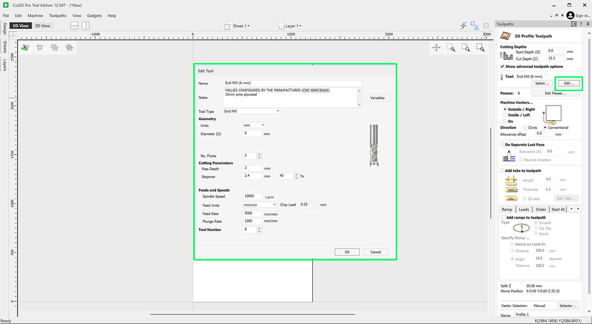
| Material | End mill | RPM | Feed rate | Stepover |
|---|---|---|---|---|
| Plywood 15mm | 6 mm · 2 flutes | 18000 | 5000 mm/min | 4.5 mm |
* This table will be updated as I gain more experience using it. Consult the FabLab for the table of parameters based on the material and milling cutter.
Runout, fixturing, alignment and toolpath strategy
In CNC machining, besides selecting the correct tool and cutting parameters, there are several physical factors that directly affect the precision and quality of the result. Among the most important are tool runout, material fixturing, material alignment, and toolpath strategy.
Understanding and controlling these aspects helps prevent machining errors, improve part quality, and reduce tool wear.
Runout (tool misalignment)
Runout is the radial deviation of the tool relative to the spindle rotation axis. In other words, it happens when the end mill does not rotate perfectly centered.
Even small deviations can cause:
- Vibrations during machining
- Uneven tool wear
- Poorer surface finish
- Dimensional errors in the part
Common causes of runout
- Dirt in the collet or tool holder
- Worn ER collets
- Poorly inserted tool
- Bent or damaged tool
- Poor tool quality
How to reduce runout
- Always clean the collet and taper before mounting a tool
- Insert the tool deep enough into the collet
- Avoid excessively long tools
- Check that the tool is in good condition
Fixturing
Fixturing refers to the system used to hold the material during machining. Proper fixturing is essential to prevent the part from moving, reduce vibrations, maintain machining accuracy, and protect the tool.
On a large-format CNC like this one, the main fixturing system is the vacuum table, which keeps the material attached to the surface by suction.
Fixturing systems used
Vacuum table
- Fast fixturing
- Good force distribution
- Allows machining of large panels
Limitations: very small parts may not hold well, and porous materials can reduce vacuum efficiency.
Screws or mechanical clamps
They are used when the material is small, vacuum is not enough, or a firmer hold is required.
Double-sided tape
Sometimes used for small parts or lightweight materials. It is a quick solution, although not always suitable for aggressive machining.
Alignment
Material alignment means placing the board correctly relative to the machine axes. If the material is not aligned with the X and Y axes, problems may appear such as:
- Misaligned parts
- Cuts that are not parallel to the edge of the material
- Assembly errors
Alignment procedure
- Place the board against a straight reference on the table.
- Check that the material edge is parallel to the X axis.
- If necessary, slightly adjust the material before activating the vacuum.
- Visually check that the work origin matches the design.
Toolpath strategy
Toolpath strategy defines the order and way in which the tool machines the material. A good strategy helps reduce tool stress, improve surface finish quality, prevent part movement, and optimize machining time.
Operation order
- Drilling
- Engraving or pocketing
- Roughing
- Final cuts
Outer profile cuts are usually left for the end to avoid the part coming loose too early.
Tabs or holding bridges
For full cuts, it is recommended to add tabs (small material bridges) to prevent the part from coming loose before machining finishes. These small bridges keep the part attached to the stock until the end of the process and can later be cut or sanded easily.
Cutting directions
Conventional milling
- The tool cuts in the opposite direction to the feed
- More stable in some materials
- Lower risk of grabbing
Climb milling
- The tool cuts in the same direction as the feed
- Better surface finish
- Less friction
Safety rules
A large-format CNC router combines high-speed rotating tools, chip projection, high noise levels, moving parts, and risks associated with poor material fixturing. Safe use depends on following the correct procedure and maintaining constant supervision during machining.
There must always be two people present when operating the machine.
1) Personal protection and proper clothing
- The use of safety glasses and hearing protection is mandatory.
- Always tie back long hair.
- Do not wear loose clothing, bracelets, cords, or hanging objects.
- Wear appropriate footwear and keep the area clear.
2) Emergency stop and machine control
- Know the location of the emergency stop before starting.
- Stop the machine immediately if there is a collision, abnormal vibration, or the material moves.
- If the machine enters a blocked or warning state, use the program reset to return to normal mode.
3) Material fixturing and tools
- Check that the material is properly fixed before starting.
- Never machine a poorly fixed part or one with unsupported floating areas.
- Verify that the tool is correctly mounted and properly calibrated.
- Incorrect numbering in the ATC rack can cause serious errors.
4) Chips, extraction, and cleaning
- Always activate extraction before starting the job.
- Monitor proper chip evacuation during machining.
- Do not accumulate waste on the table or leave dirt around the machine.
- At the end, clean the area for maintenance reasons and out of respect for the shared workspace.
5) Moving parts and work area
- Do not place your hands inside the machining area while the machine is running.
- Keep a safe distance from the gantry and spindle while they are moving. The area is marked on the floor.
- Do not try to manually correct a part or remove waste while the machine is running.
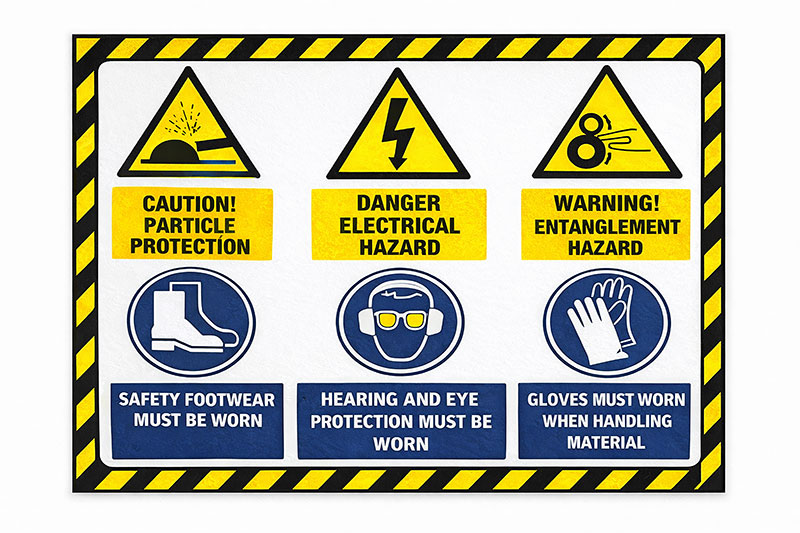
Safety checklist (visual)
Quick checklist that I follow before starting and during a CNC machining job.