Penny Pal Project Development
From Sketches to Questions
I started with an idea that made sense in my head. Then I spent weeks discovering all the ways reality disagreed with it, until the object and I finally reached an agreement.
The images capture that negotiation.
The earliest sketches were not solutions. They were questions.
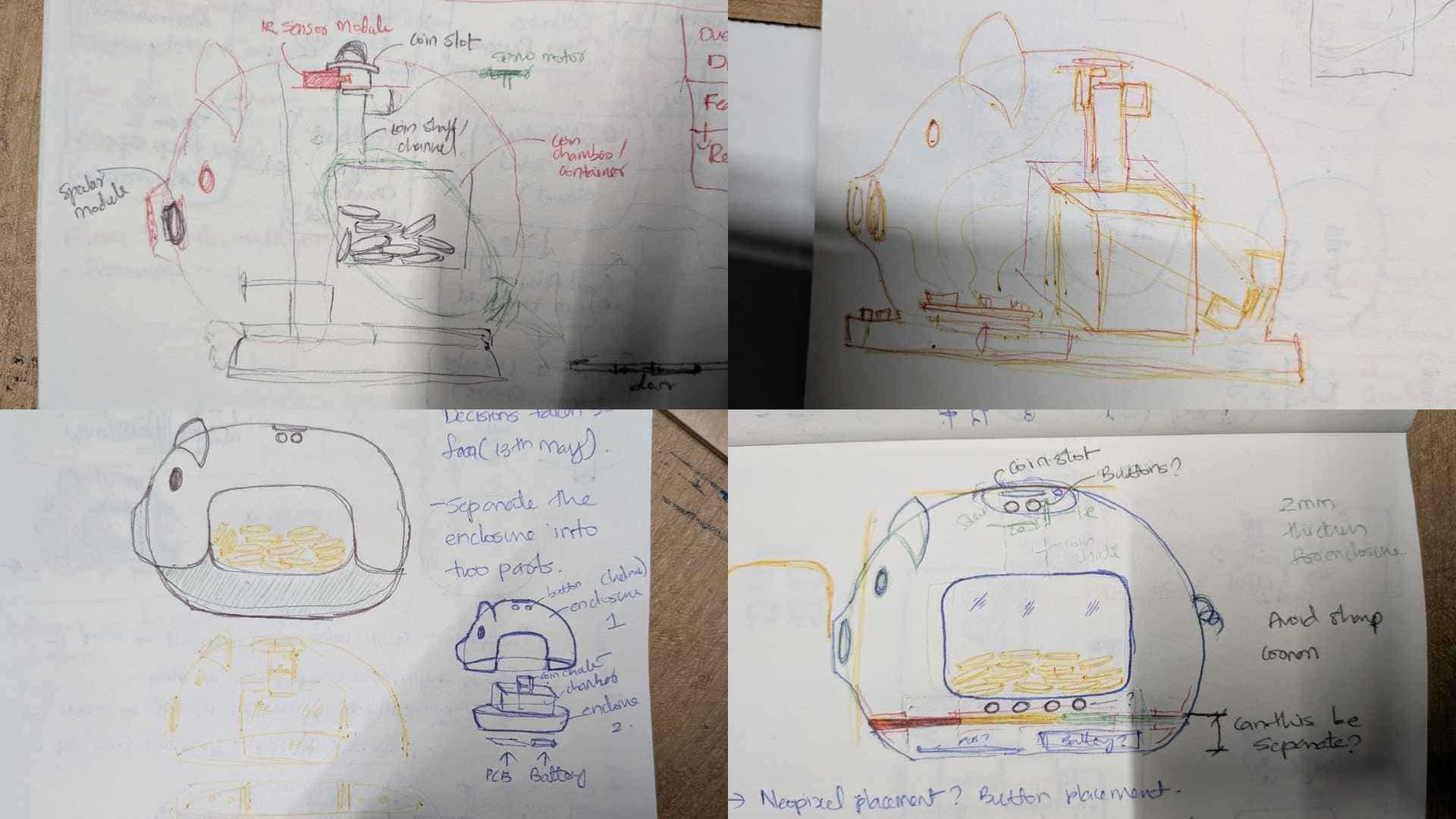
Penny Pal first existed as rough outlines, notes scribbled in margins, arrows pointing to possibilities, and dimensions that would later change. The sketches were less about defining a final form and more about getting thoughts out of my head and onto paper.
At that stage, every line represented uncertainty.
Where should the buttons go? How should a child interact with it? Should the coins be visible? How would the enclosure split, print, and assemble? Where would the electronics fit? How would the coin be sensed, stopped, released, and collected? If not a servo, then a solenoid, and where would that go? The drawings helped me think through these questions, but they did not answer them. Every sketch led to another question, another prototype, and another round of trial and error.
Discovering That Every Decision Has Consequences
One of the earliest lessons was realizing that nothing in the project existed independently.
Moving a button affected PCB routing. Changing the coin path affected sensor placement and reliability. Adjusting the wall curvature affected assembly. The pig's capsule-shaped shell was not just an enclosure; it was the structure that held everything together.
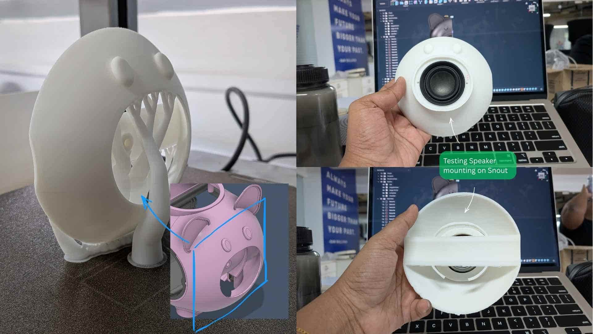
The speaker was perhaps the only exception. From the beginning, it lived in the snout.
Adding one component often created two new problems somewhere else. Gradually, the project became a web of dependencies where every decision affected several others. I stopped thinking about individual parts and started thinking about relationships between parts.
Designing With My Hands, Not Just CAD
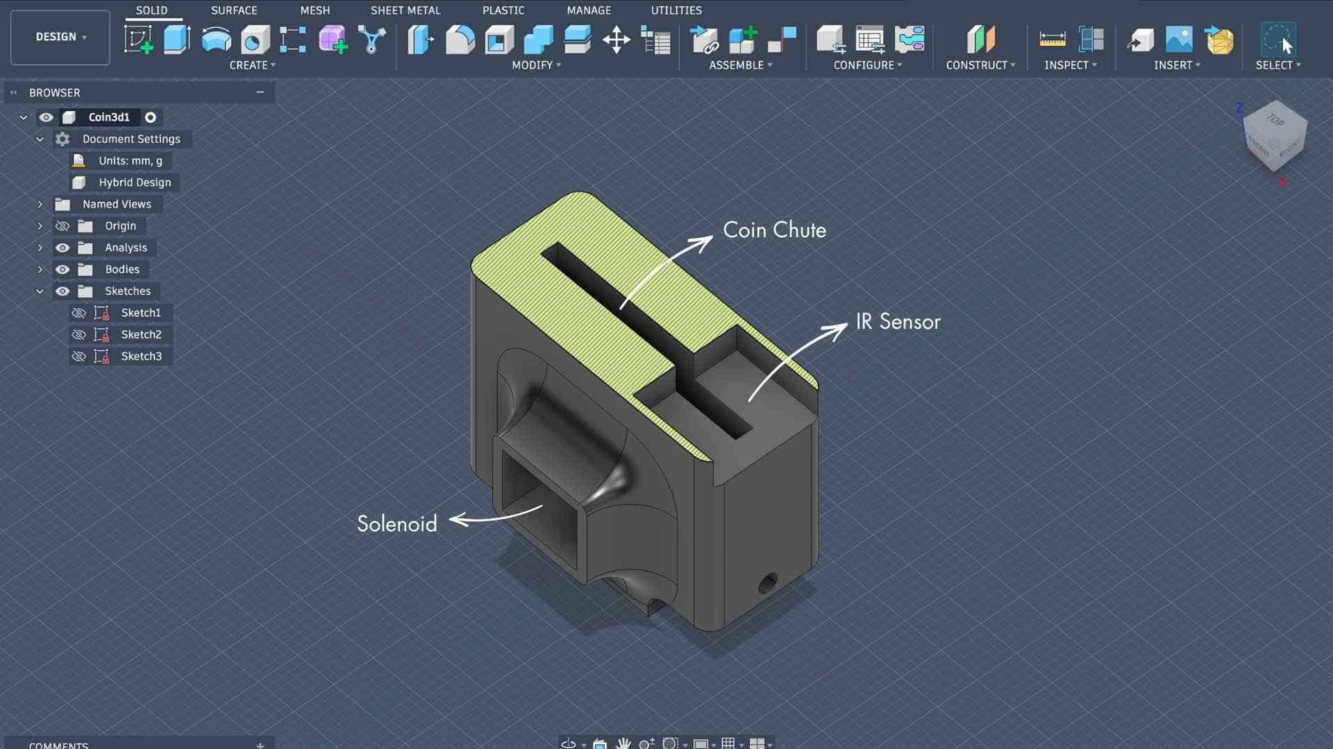
At the start of System Integration week, the only thing I could confidently build was a paper model of the coin chute with the IR sensor and servo attached to it. That simple folded prototype became the starting point for the entire project.
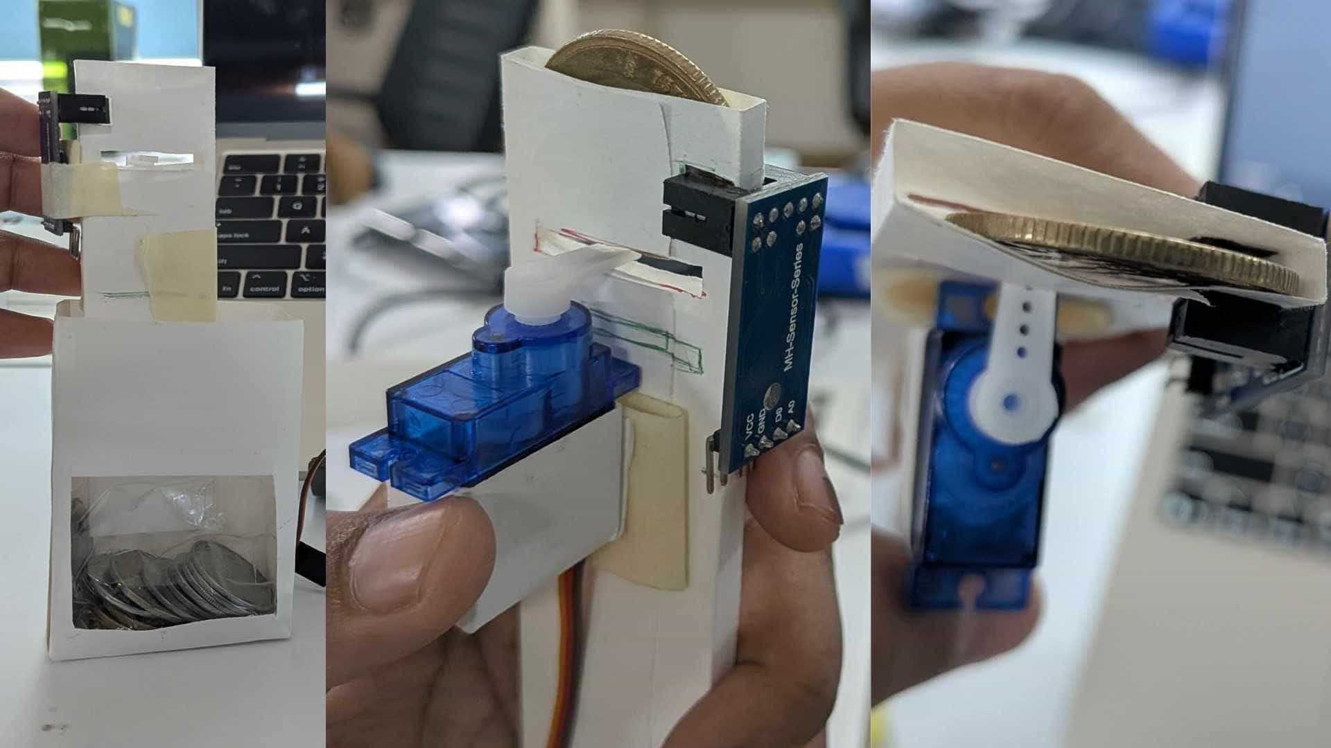
From there, it moved into Fusion, and slowly the other parts began finding their place, the breakout PCB, buttons, speaker, battery, and everything else.
I needed something physical to begin with. Something to hold, touch, and test. My brain could not keep the entire project inside a screen.
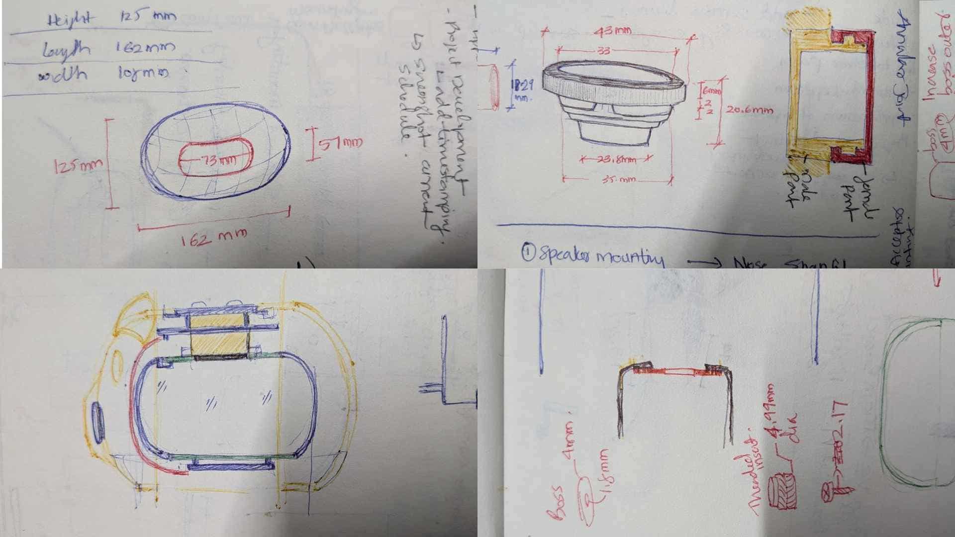
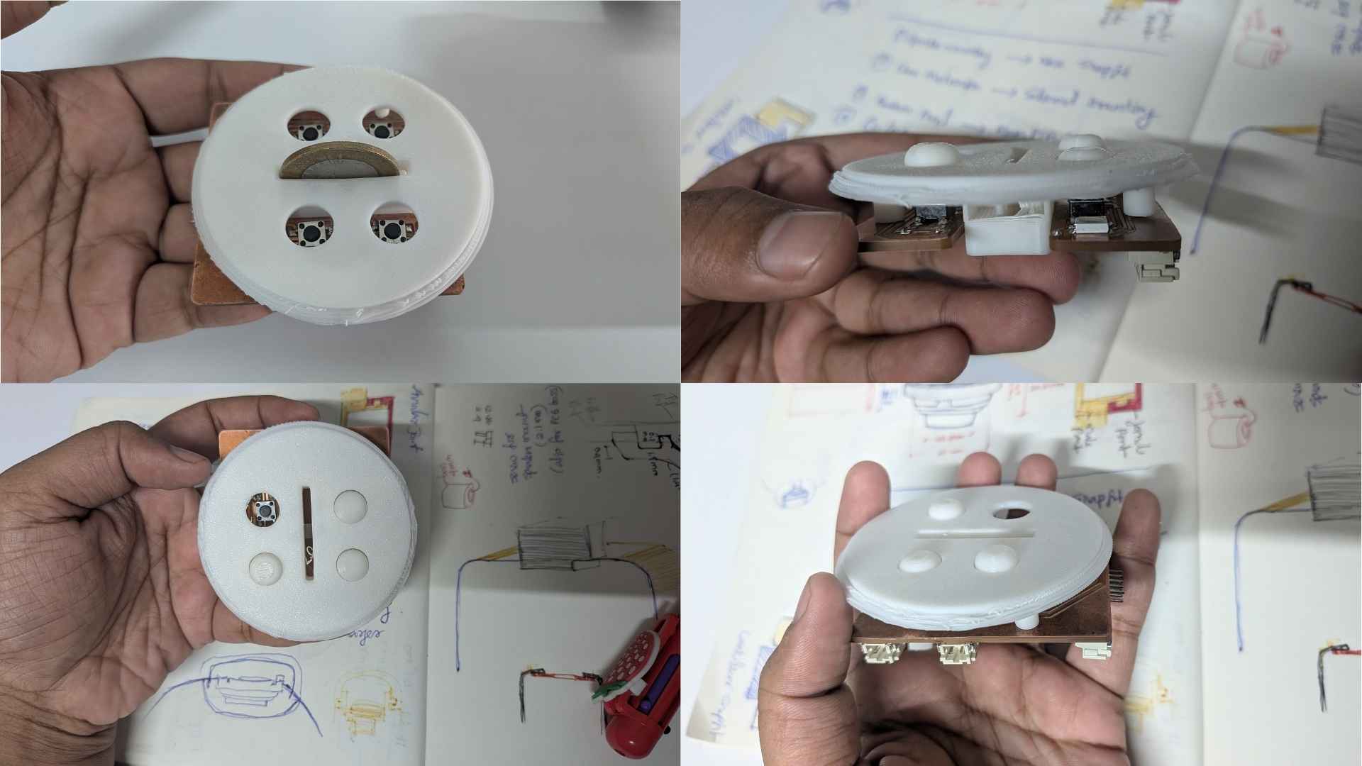
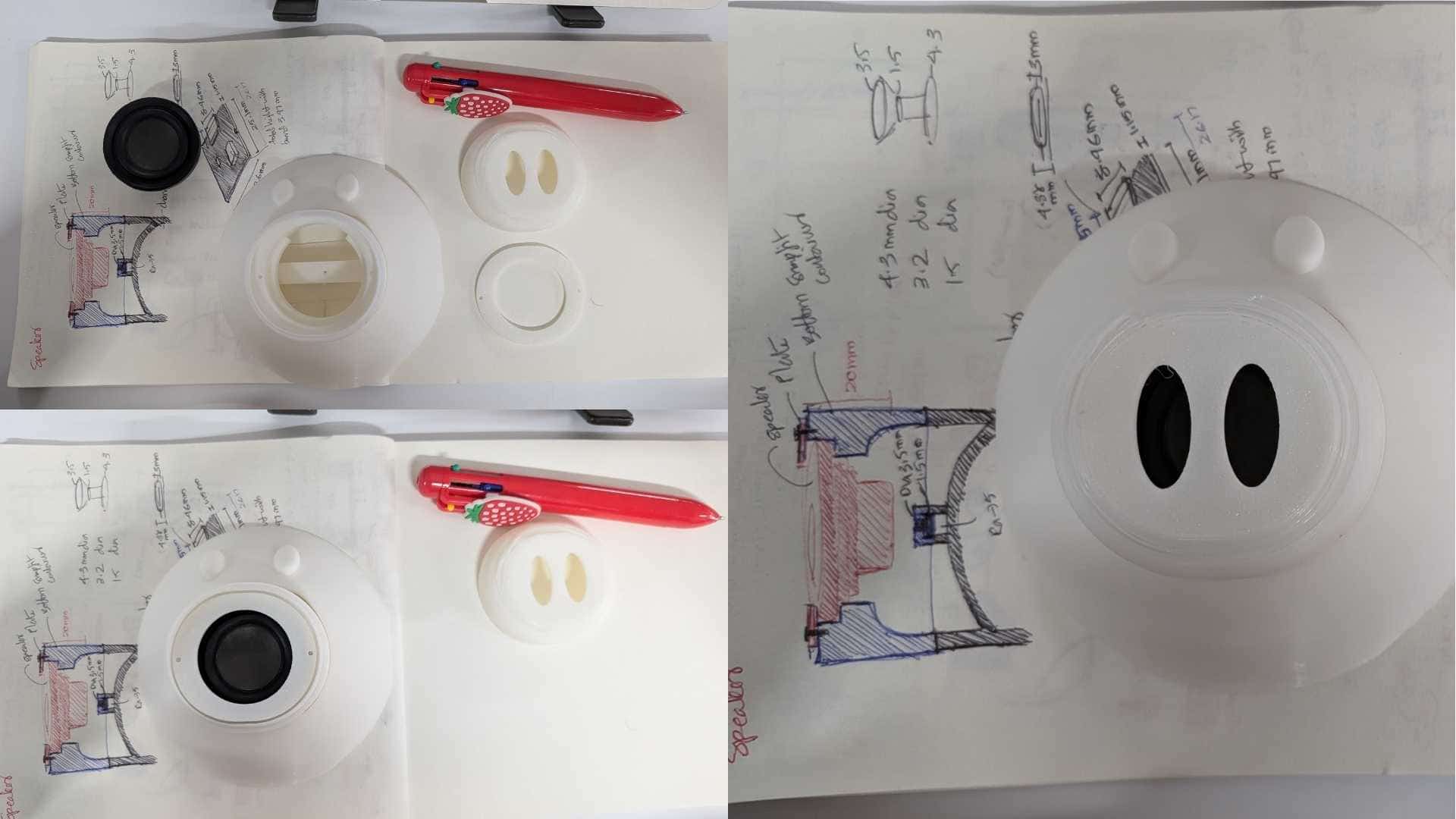
The speaker enclosure became a good example of this shift.
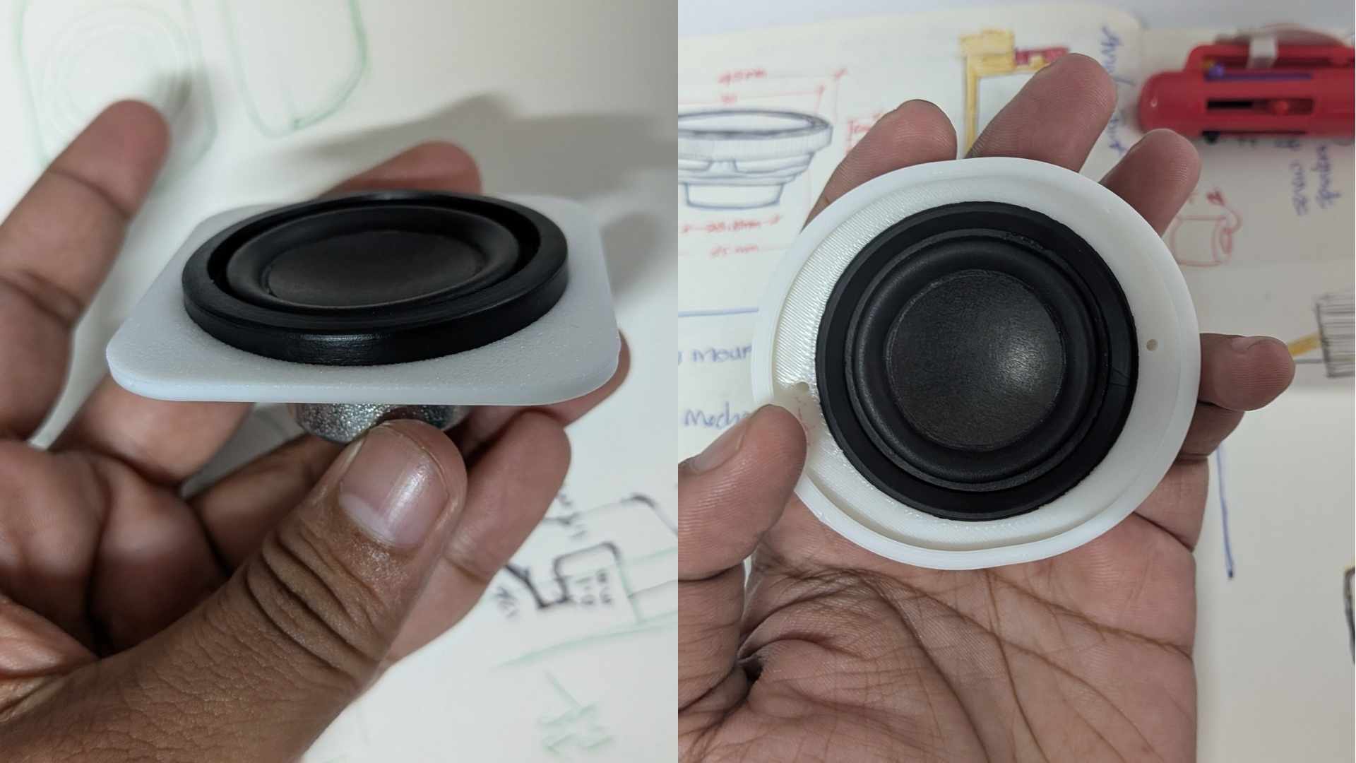
Initially, it was just a part that needed to fit inside the snout. But through repeated measuring, prototyping, and testing, it became clear that it was influencing much more than sound.
It affected assembly, cable routing, internal space, weight distribution, and even the character of the pig's face. The speaker itself was surprisingly heavy, and I did not want the pig slowly tipping onto its nose.
The annular snap-fit emerged through several iterations, not because it was planned, but because each version revealed something the previous one had missed.
Keeping a speaker inside the snout was easy. Making it feel like it belonged there was the real challenge.
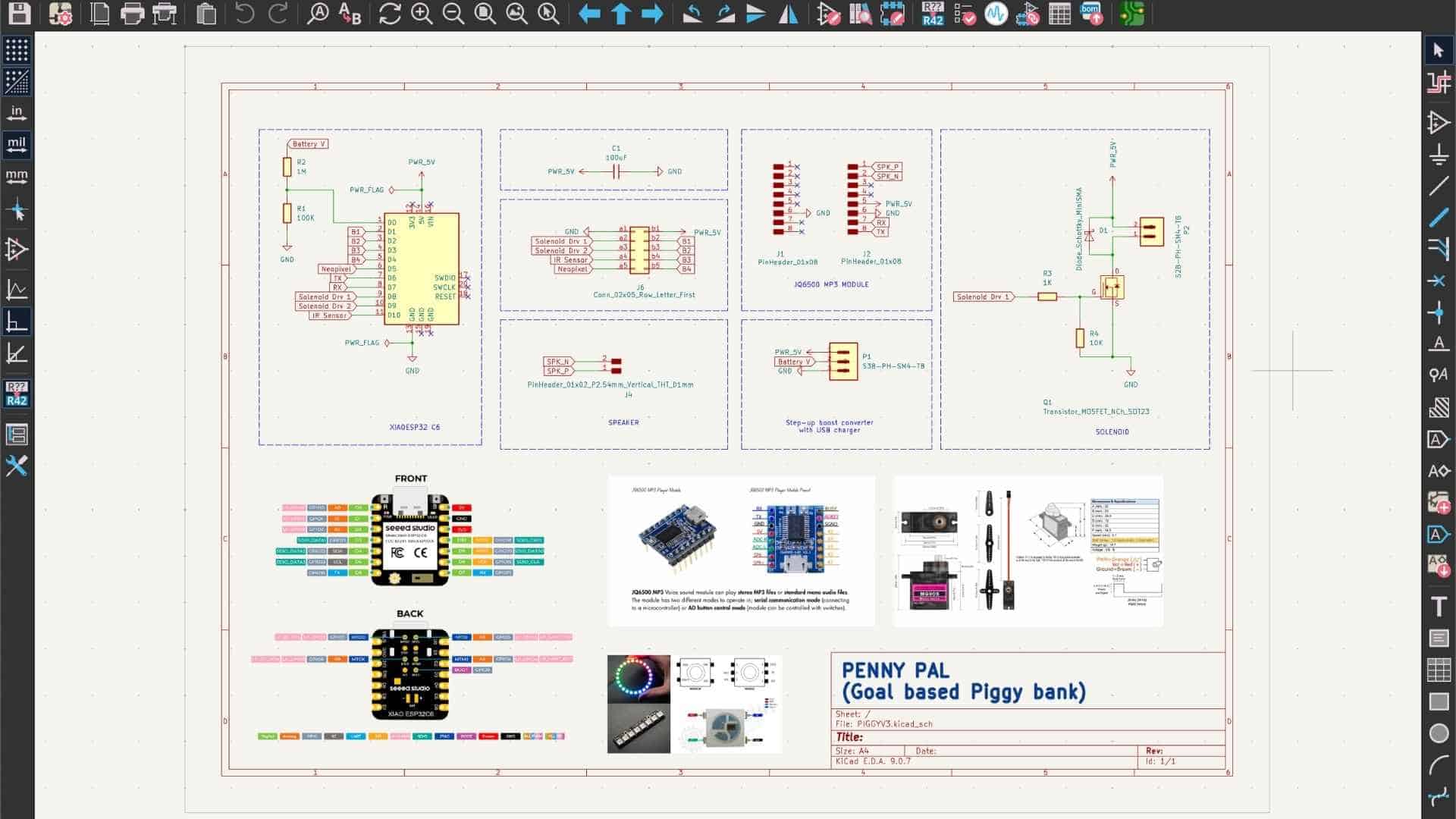
Electronic Design and Production
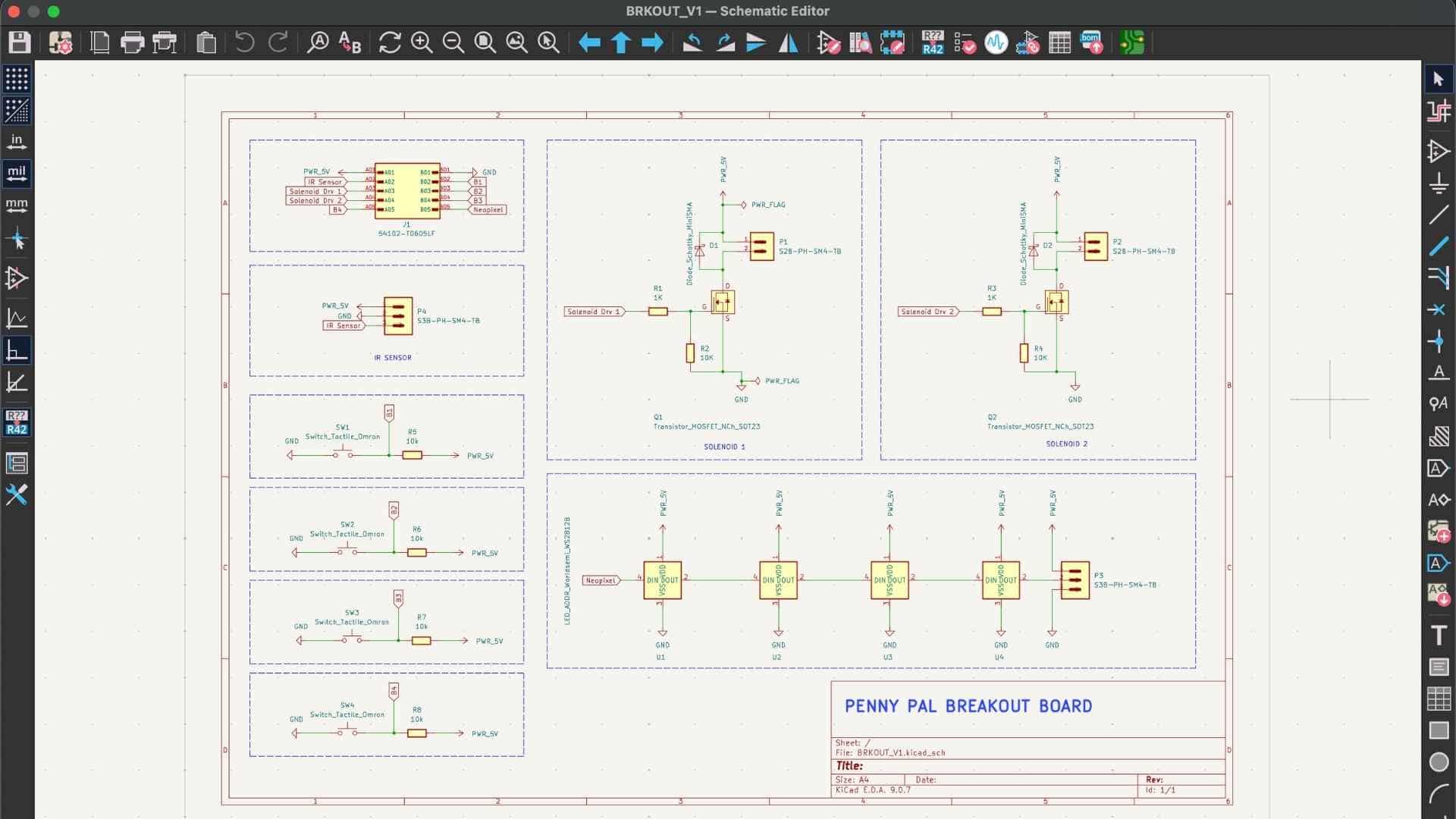
PCB Main Board Design on KiCAD
Schematics
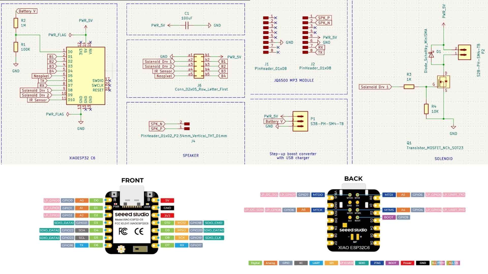
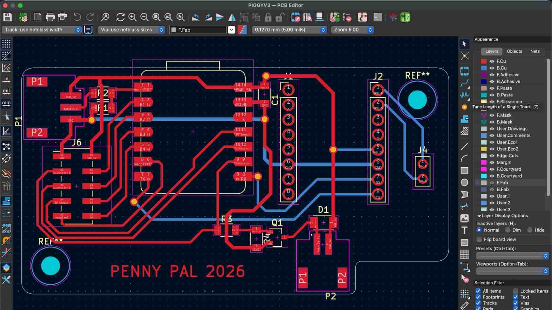
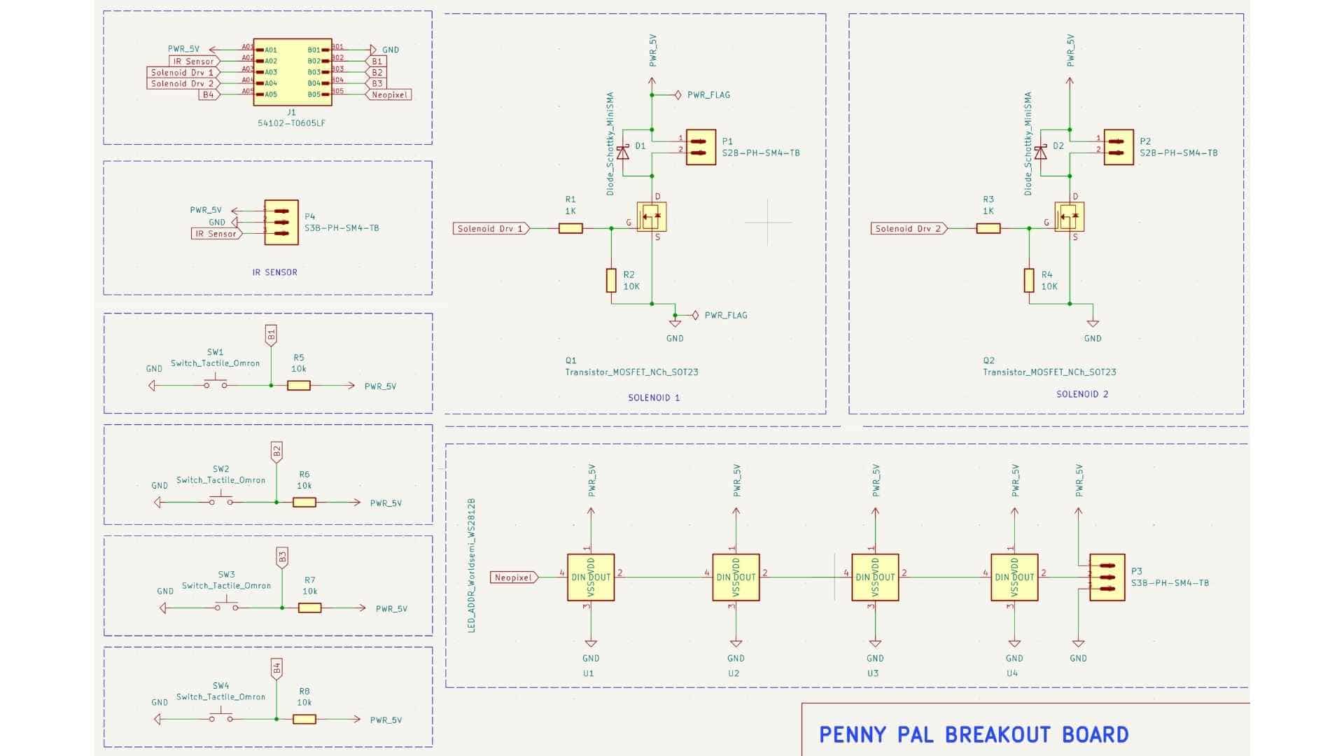
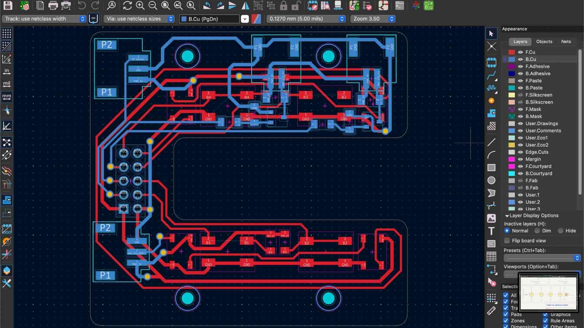
PCB Breakout Board
Schematics
Project Development so far
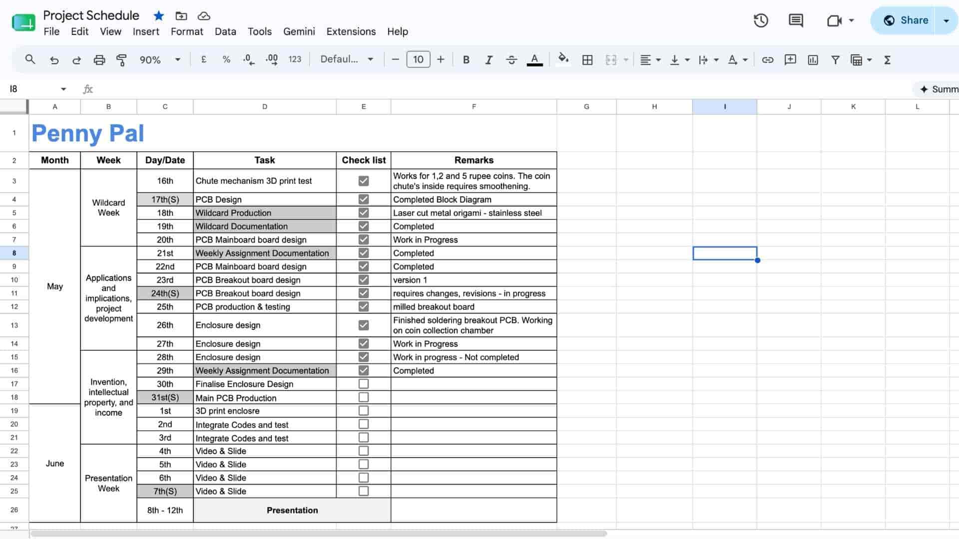
What tasks have been completed, and what tasks remain?
Most of the project has been completed, including the PCB, enclosure, fabrication, Firebase integration, mobile app, audio feedback, NeoPixels, and communication between the app and the ESP32-C6.
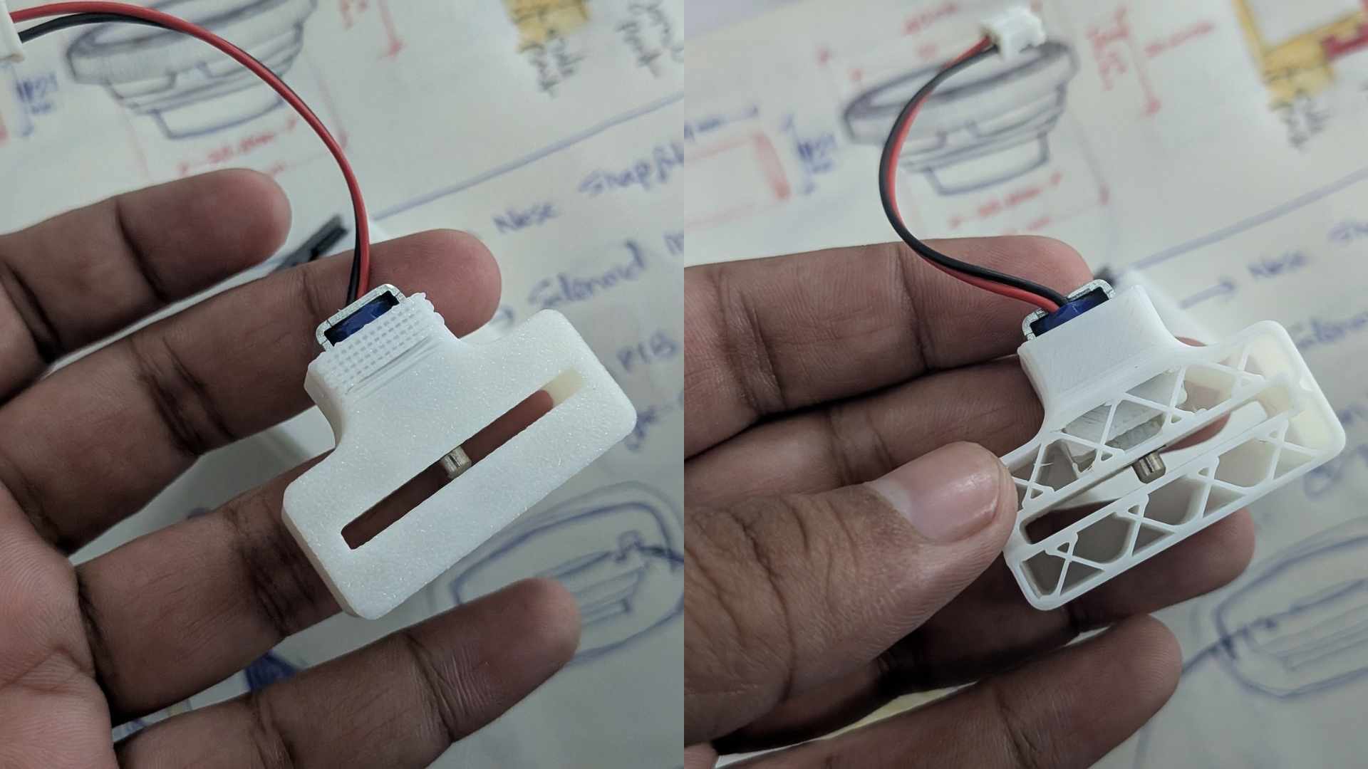
The remaining work focuses on refining the experience. I still need to integrate the second solenoid for unlocking the reward tray, add startup feedback, and complete a few milestone interactions.
Test Prints and Iterations
Learning Through Failure
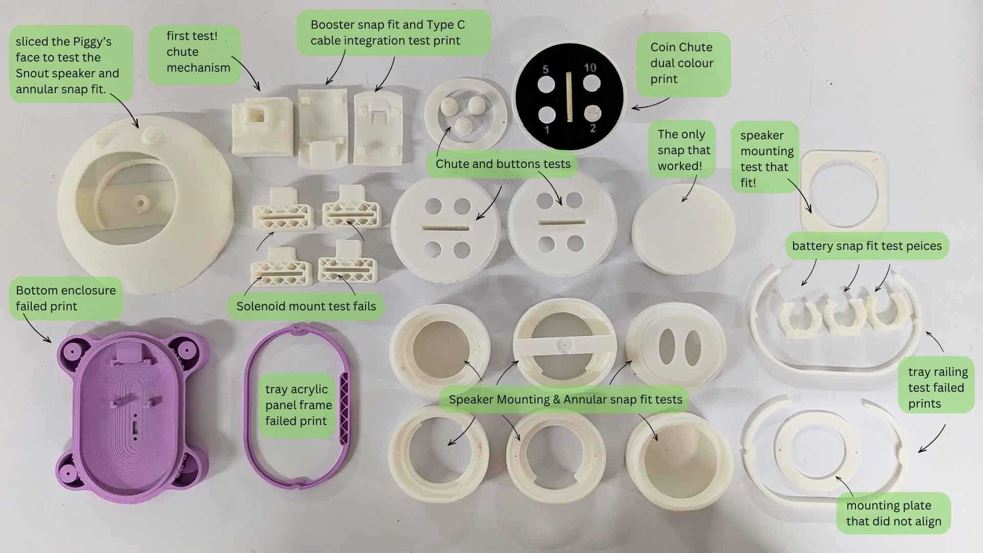
There were many moments when things worked perfectly on their own but failed once they became part of the system.
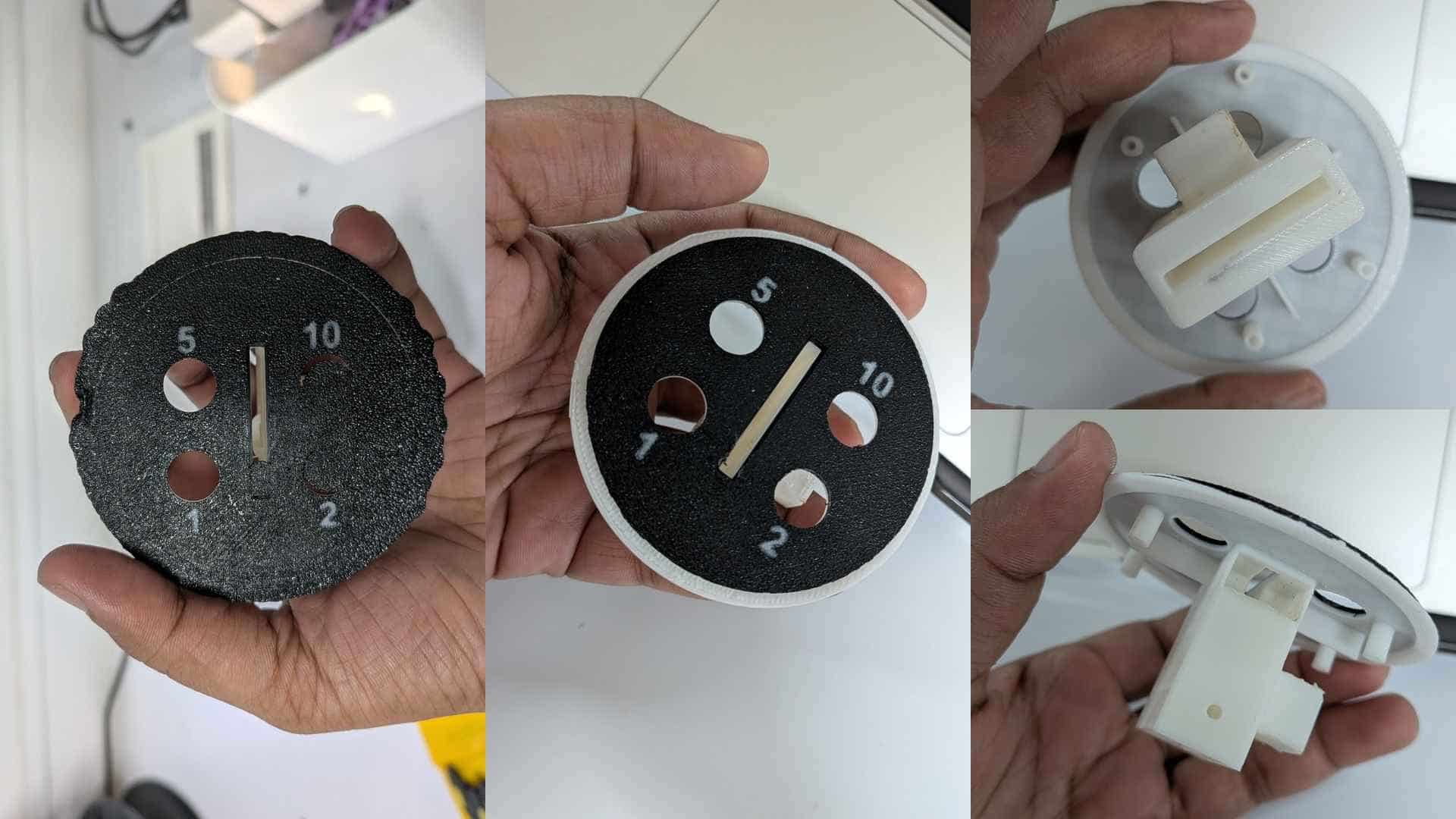
The coin acceptor module was particularly sensitive because so many other elements depended on it: the breakout PCB, solenoid, IR sensor, NeoPixels, push buttons, and overall interaction flow. Even the height of the 3D-printed buttons had to be carefully tuned to match the tactile switches on the PCB.
What will happen when?
Once a savings goal is set through the app, Penny Pal begins tracking deposits. Each valid deposit triggers feedback, and milestone rewards are activated as progress increases.
When the savings goal is reached, the reward tray unlocks, allowing the user to access their savings. After reinserting the tray, the lock can be reset for the next saving cycle.
Some parts looked great but could not be assembled. Electronics fit perfectly in CAD but not in reality.
The second solenoid had to be moved into a leg. The PCB had to be redesigned. An IR sensor wire I forgot to account for required sanding after printing. Connectors needed access. The ten-wire ribbon cable became so confusing that I started taking reference photos every time I unplugged it.
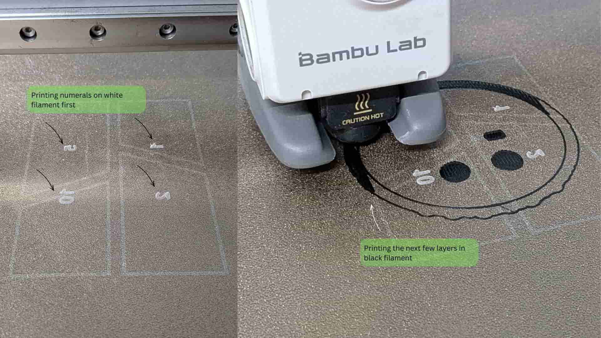
The denomination buttons needed labels. The NeoPixels needed to illuminate them. That led to experiments with dual-colour printing.
A few millimetres of clearance for a USB-C module or a battery mount could force an entire assembly to be redesigned.
The drawer itself appeared only a few days before the final presentation. Until then, the plan was a hinged door. The drawer emerged out of frustration more than certainty, but once it appeared, it solved multiple problems at once.
Adding transparent acrylic windows became one of my favourite decisions. It allowed users to see their growing collection of coins instead of hiding it away. It also gave me an excuse to pause a print, insert acrylic, and continue printing over it, a surprisingly satisfying process.
Some days felt productive.
Other days felt like uncovering new problems.
Looking back, both were part of the same process.
What's working? What's not?
The core functionality is working. The app can set a savings goal, the piggy bank tracks deposits, updates Firebase, and provides audio and visual feedback.
The reward tray unlocking mechanism using the second solenoid is yet to be programmed.
What questions need to be resolved?
The main challenge is integrating all the feedback systems smoothly. As the project grew, the code became more complex and needs some cleanup and organization.
The second solenoid also requires further testing to determine the correct activation timing and behavior.
From Development to Integration
The prototypes, failed prints, mechanism experiments, PCB iterations, and design refinements documented on this page were all attempts to solve individual problems. Each test answered a question, revealed a constraint, or informed the next design decision.
While these development logs explain how Penny Pal evolved, they only show parts of the story. The real challenge was bringing all of these independently developed components together into a single product that could function as a cohesive system.
Once you've explored the design journey, continue to the final section of the System Integration page to see how the electronics, mechanisms, enclosure, user interface, and internal architecture ultimately came together to form the finished Penny Pal system.
View Final System Integration →What have you learned?
I learned that not every problem needs to be solved before starting. Many solutions only become clear through prototyping and testing.
I also learned that design decisions often change during development. For example, I originally planned to use a hinged door, but later switched to a drawer because it was easier to implement and fabricate. This turned out to be a better solution, as it also provided space for the solenoid locking mechanism.
See Penny Pal in its Final Form
You've explored the development process, the design decisions, and the countless iterations behind Penny Pal. If you've already seen how everything comes together in the System Integration page, it's time to visit the Final Project page to see the completed product presented as a whole.
View Final Project →