Week 16: System Integration
Assignment: Design and document the system integration for your final project
Project Contextualization
Traditional piggy banks introduce the habit of saving, but they are fundamentally passive objects. Money is dropped into a container with little awareness of the amount being saved, the purpose behind it, or progress toward a specific goal. While effective as a simple storage device, they offer limited engagement and provide no structured feedback that supports financial learning.
Penny Pal reimagines the piggy bank as an interactive educational product designed to promote goal-based saving. Instead of simply collecting coins, the system encourages children to actively identify each coin denomination before it is accepted. This deliberate interaction transforms saving from an automatic action into a conscious decision-making process.
The project combines physical and digital elements to create a more engaging saving experience. A companion mobile application allows parents to define savings goals and monitor progress remotely. The piggy bank responds to each deposit with audio and visual feedback, acknowledges milestones, and unlocks only when the savings goal has been achieved.
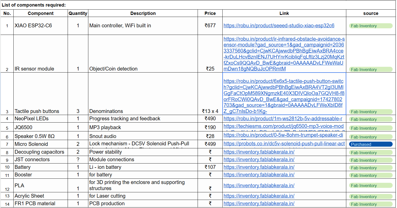
At a technical level, Penny Pal integrates:
The project sits at the intersection of product design, embedded electronics, digital fabrication, and interaction design. It explores how a familiar object can be transformed into a tangible learning tool that supports behavioral development through feedback, participation, and reward.
By combining active participation with goal tracking and positive reinforcement, Penny Pal aims to make saving more intentional, motivating, and educational for children.
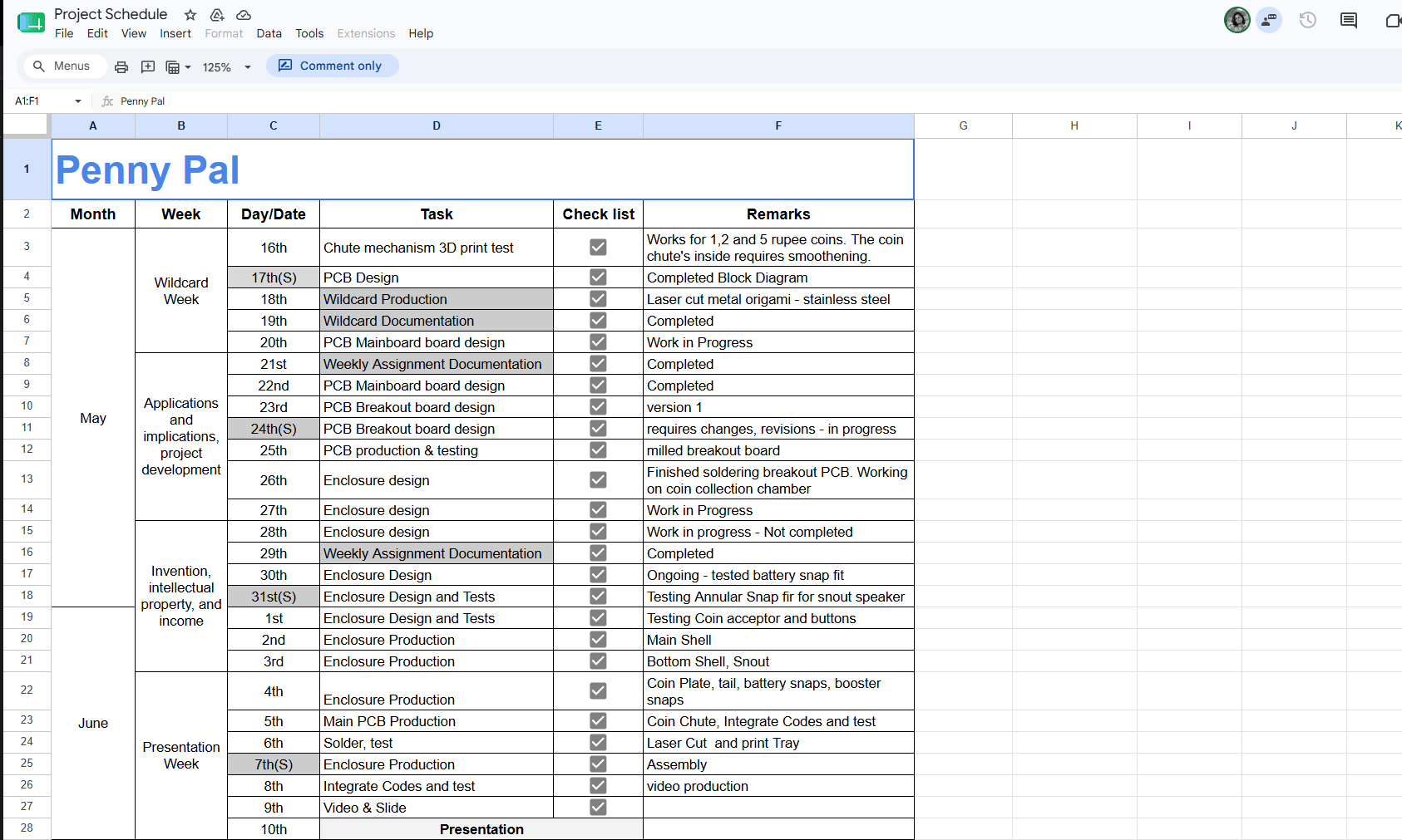
Penny Pal - Final Project Development Plan
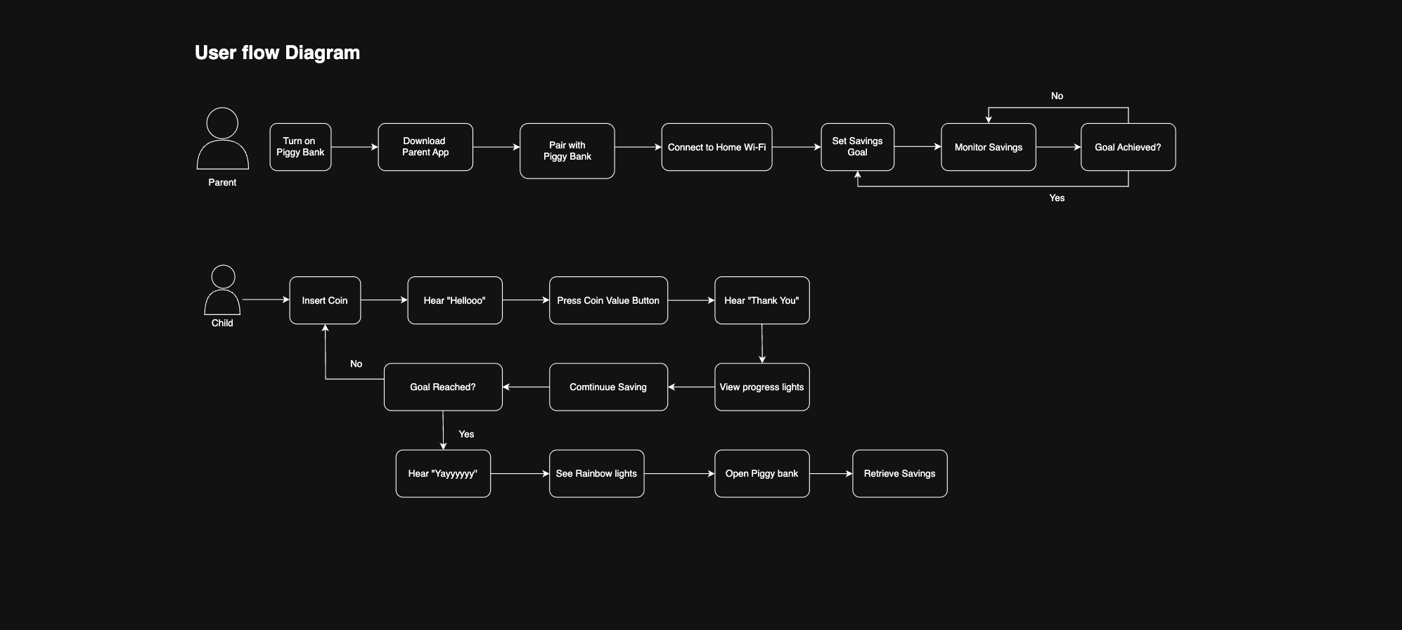
User Flow Diagram
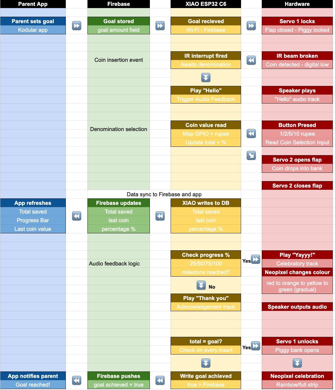
Functionality Diagram
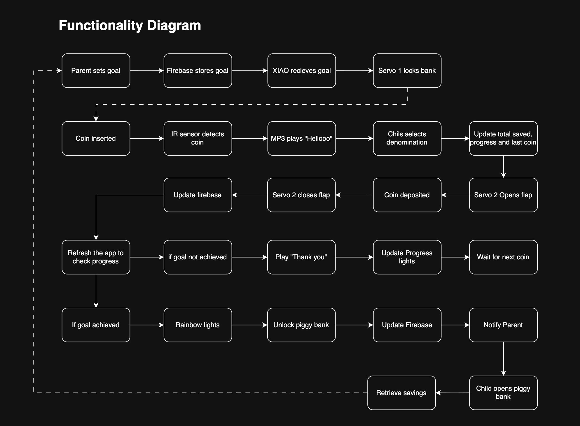
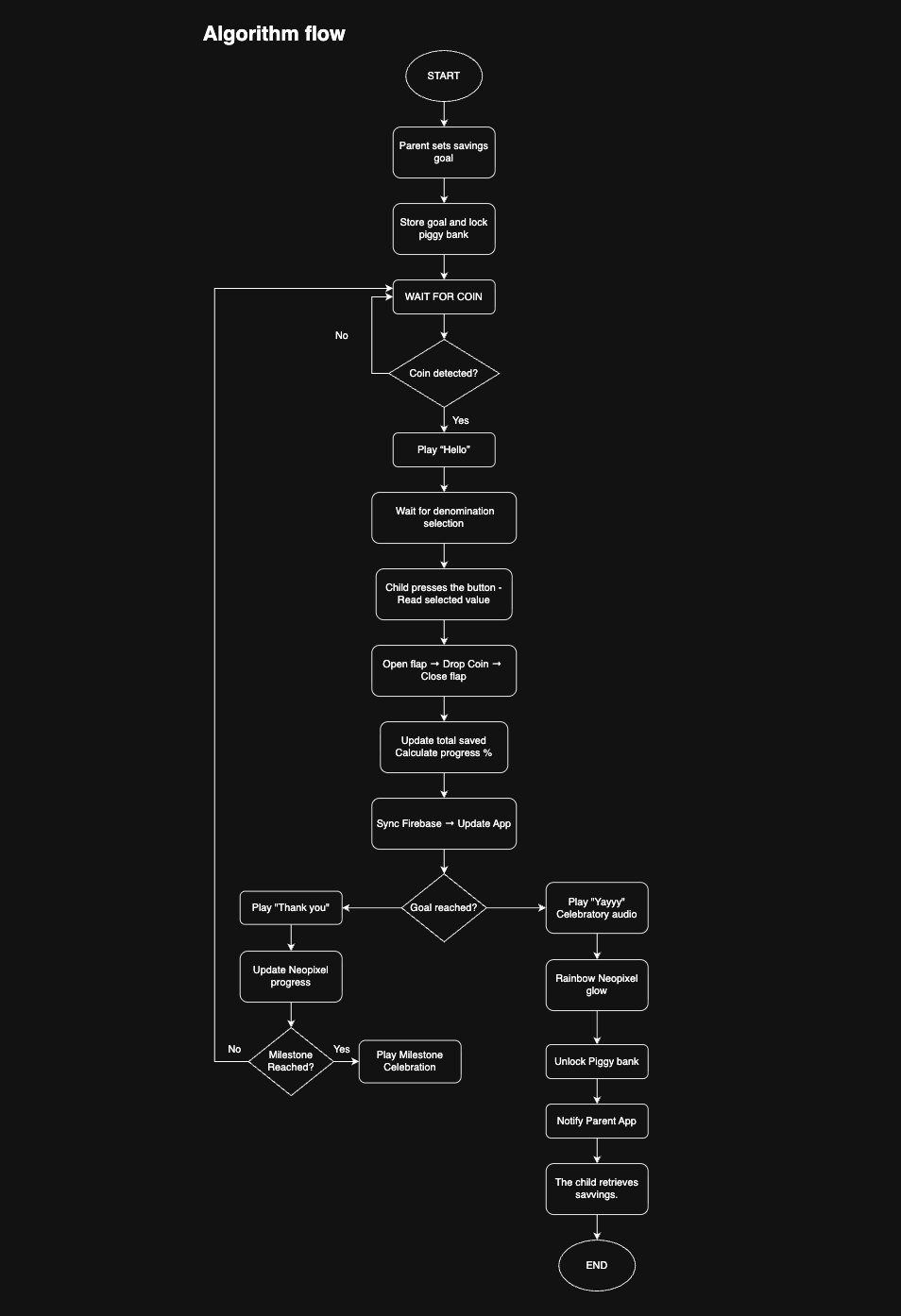
The Interaction Flow
0. Set the Goal: Before saving begins, the parent sets a savings goal through the companion app. The goal is sent to Penny Pal via Wi-Fi, and the piggy bank locks.
1. Wait: The system remains idle while the IR sensor continuously monitors the coin slot.
2. Detect: A coin is inserted. The IR beam is interrupted and the system detects the coin.
3. Prompt: A greeting sound and visual cue indicate that a coin is waiting and a denomination must be selected.
4. Identify: The child observes the coin and recognizes its denomination.
5. Decide & Confirm: The child presses the corresponding denomination button.
6. Accept: The flap opens, the coin drops into the chamber, and the flap closes.
7. Acknowledge: The system updates the savings total and responds with sound and light feedback.
8. Celebrate: At 25%, 50%, 75%, and 100% progress, milestone feedback is triggered.
9. Return: The system returns to idle and waits for the next coin.
10. Goal Achieved!: When the goal is reached, the piggy bank celebrates, unlocks, and the child retrieves the savings.
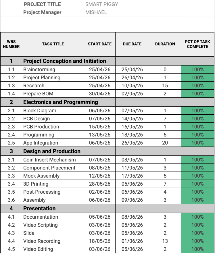
Algorithm Diagram
Piggy Bank Form Exploration
During the enclosure development phase, I collected a wide range of piggy bank references from online marketplaces, design communities, and social media. The intent was not to replicate any specific form, but to understand how broadly the piggy bank archetype has been interpreted across different cultures, materials, and design styles.
The references range from:
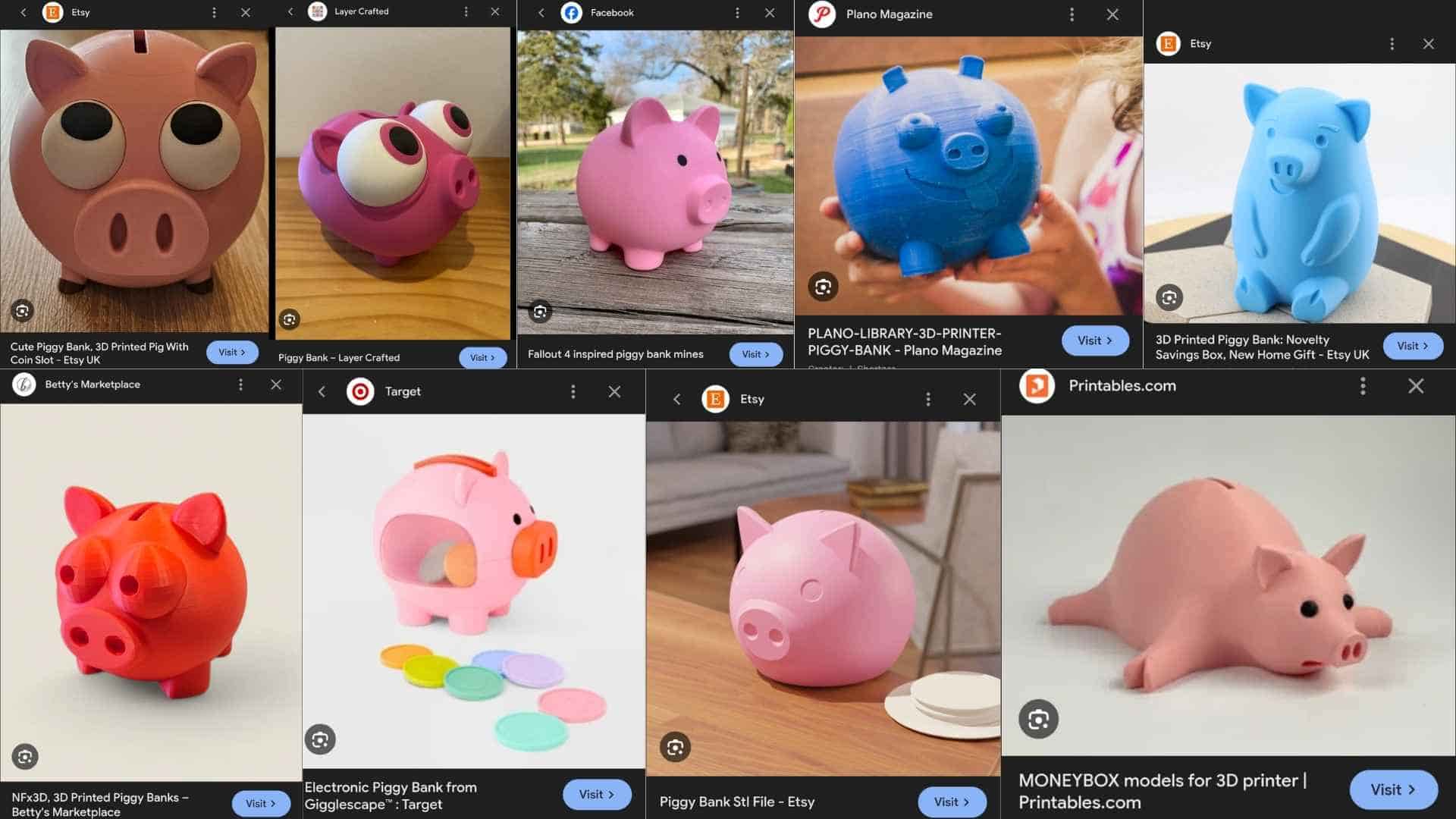
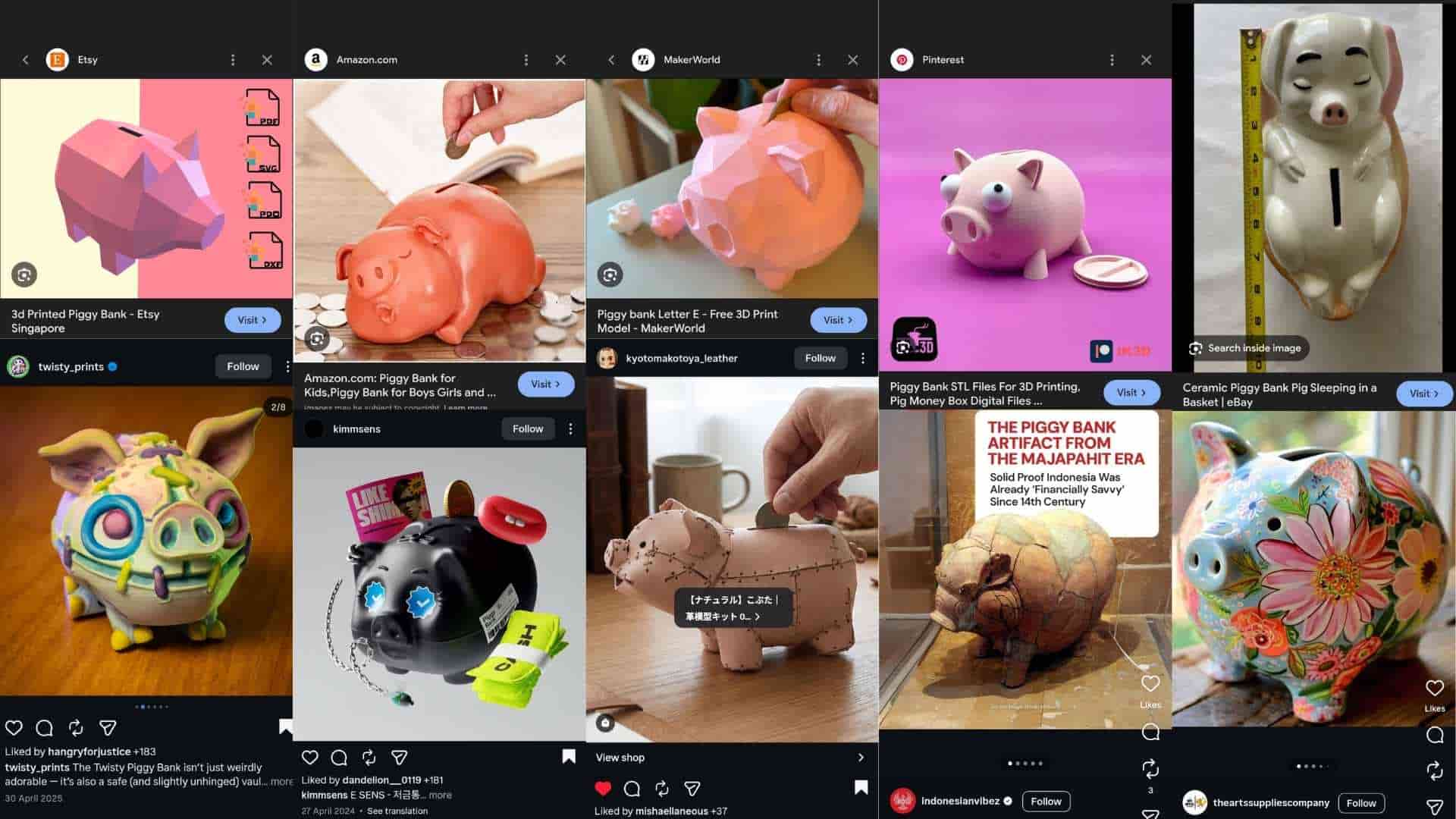
This exercise reinforced an important observation: the visual language of a piggy bank is highly flexible. There is no single “correct” form. As long as a few recognizable cues are retained, such as the snout, ears, and coin slot, the object remains immediately identifiable.
For Penny Pal, this insight was useful because it shifted the design focus away from finding a perfect external form and toward resolving the internal mechanism and user interaction. The enclosure serves as a carrier for the functional system rather than the primary innovation.
At the same time, this exploration provided confidence that the final form can be developed with significant creative freedom while still preserving the familiarity and emotional appeal associated with the piggy bank archetype.
Design Intent
The final enclosure aims to:
In this sense, the reference board functions as a reminder that while the internal mechanism defines the product’s novelty, the external form remains open to interpretation. A piggy bank can take many visual expressions; what matters is that the design supports the intended interaction and meaning.
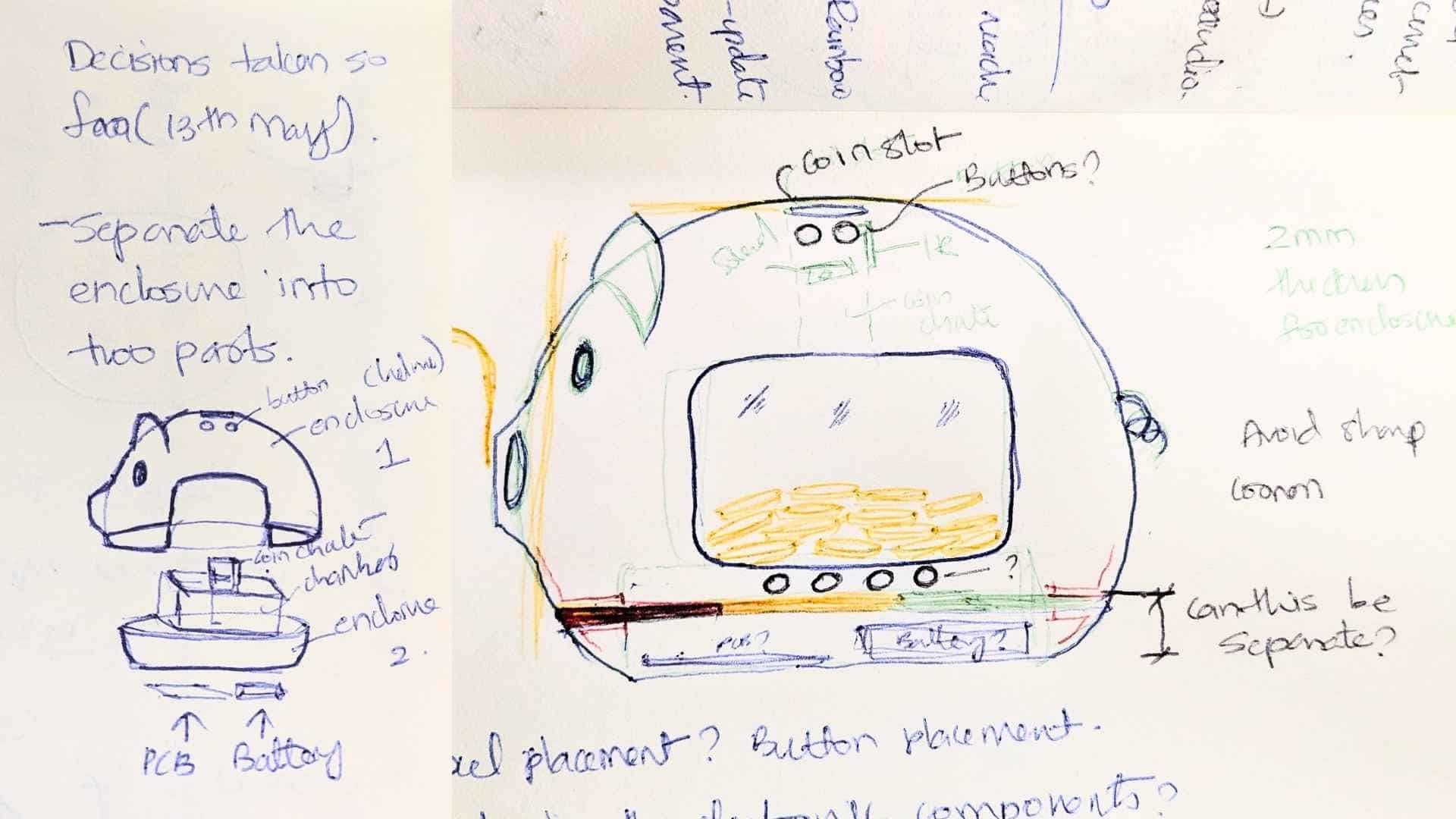
Initial Layout and Packaging Concept
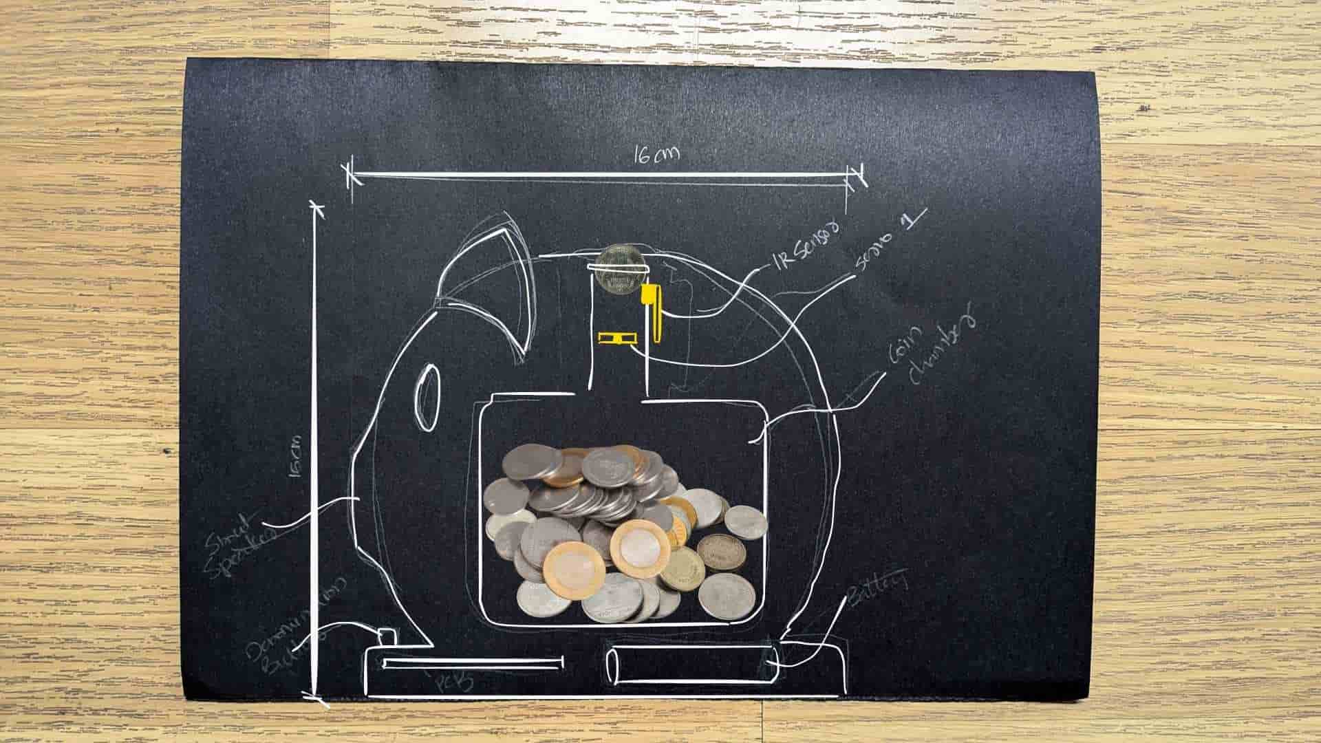
Concept sketch showing the internal layout and approximate dimensions of the Smart Piggy prototype. The enclosure is based on a simplified pig silhouette measuring roughly 16 × 16 cm. A coin is inserted through the slot at the top, where an IR sensor detects its presence and a servo-actuated gate controls whether it is accepted. Once approved, the coin drops through an internal channel into the central storage chamber. Electronics, including the custom PCB and battery, are positioned around the perimeter and within the base to keep the coin compartment unobstructed. This sketch was used to evaluate spatial relationships between the mechanical components, electronics, and storage volume before developing the final CAD model.
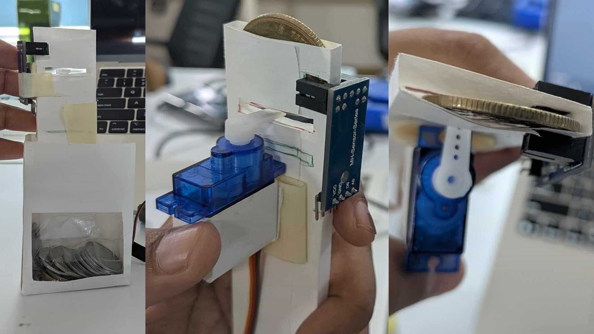
A quick proof-of-concept prototype built from paper to test the coin detection and sorting mechanism. The assembly integrates a coin chute, IR sensor, and servo-actuated flap to verify that coins can be reliably detected and redirected before entering the storage chamber. This physical mockup was used to evaluate component placement, coin clearance, and mechanical behavior prior to designing the final integrated enclosure.
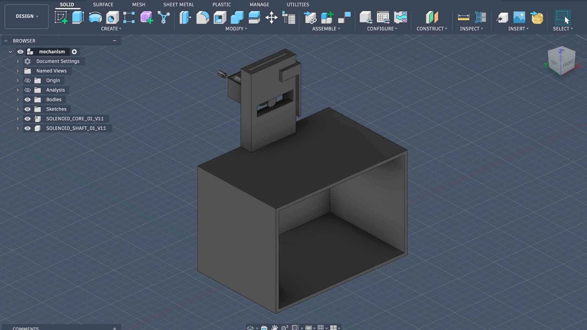
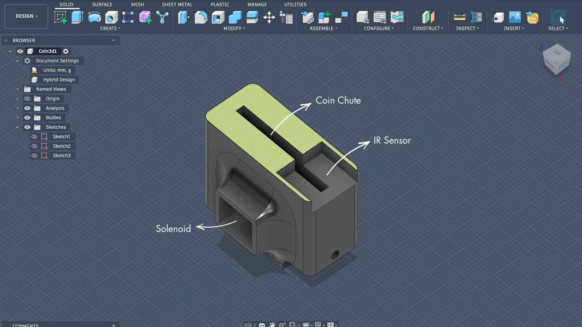
A simplified CAD model developed in Fusion 360 to translate the proof-of-concept mechanism into a manufacturable design. The model defines the relationship between the coin chute, sensor mount, actuator housing, and storage compartment, allowing key dimensions and clearances to be evaluated before integrating the mechanism into the final pig-shaped enclosure.
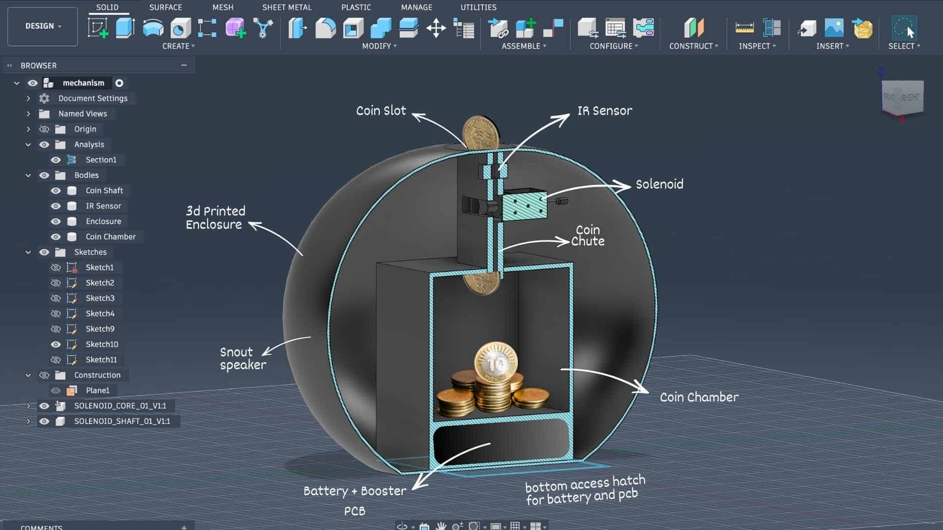
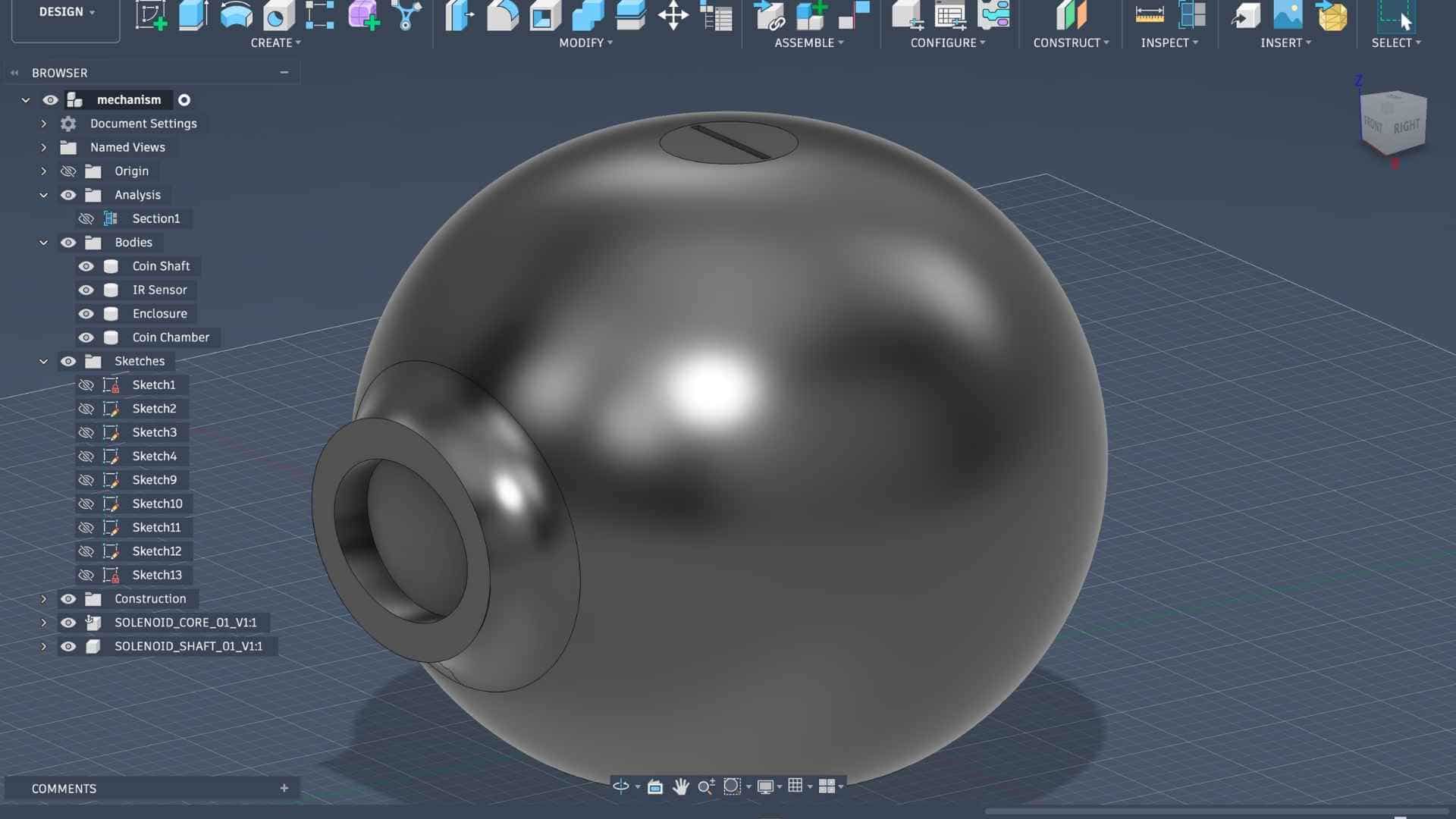
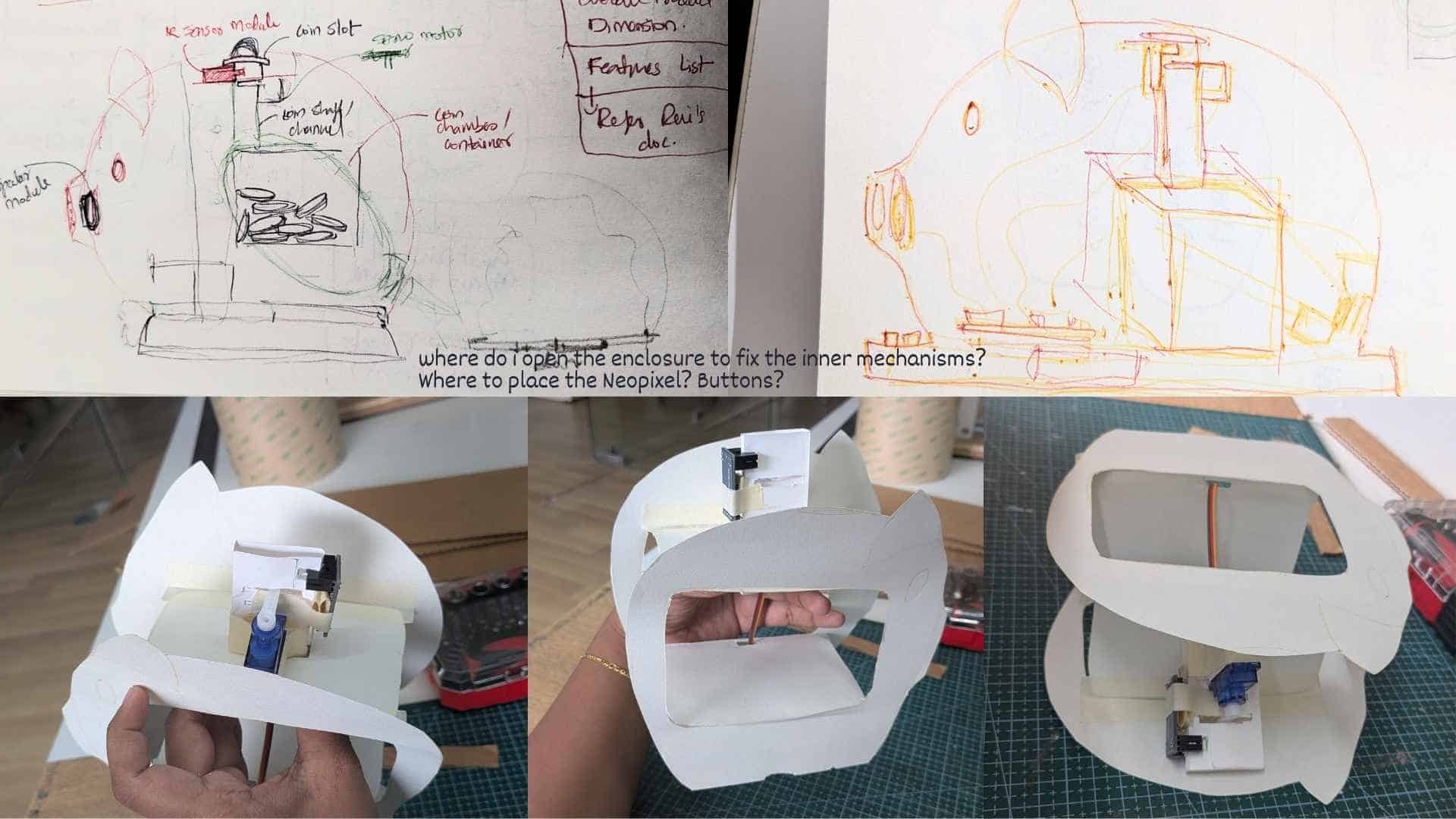
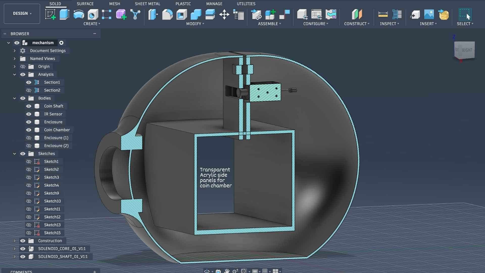
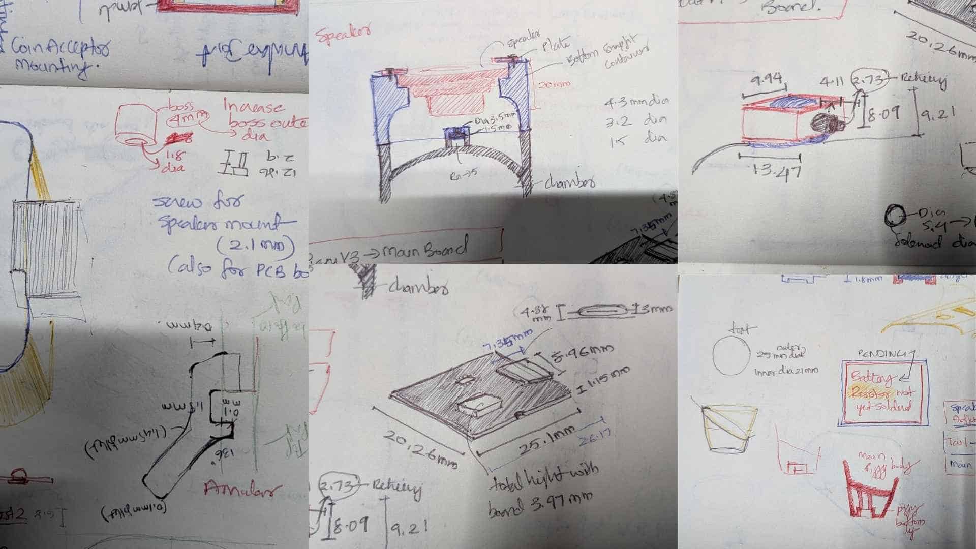
A series of CAD iterations on Fusion exploring how all the internal components fit within the pig-shaped enclosure. The initial model focused on defining the overall form, along with the coin slot and snout opening for the speaker. Section views were then used to work out the placement of the coin chute, IR sensor, solenoid, coin chamber, battery, and custom PCB. I am also planning on using transparent acrylic side panels for the coin chamber so the saved coins remain visible, along with a bottom access hatch to make it easier to assemble and service the electronics. These models helped me check clearances, refine the internal layout, and confirm that the overall design is feasible but I need to verify and remake certain parts before working on the final model.

Based on the enclosure strategy I have developed so far, the product is designed as a two-part assembly consisting of an outer shell and a functional base.
Outer Shell
The top part acts as a helmet-like cover that fits over the internal structure, enclosing and protecting the electronics and mechanisms while giving the product its final character and form. This shell integrates all of the user-facing features, including the coin slot, button interfaces, and the snout, which also serves as the speaker opening.
Functional Base
The bottom part serves as the primary structural housing for all internal components. The upper side contains the coin chamber and coin chute, along with mounting locations for the button breakout board, IR sensor, NeoPixel LEDs, and actuators such as servos or solenoids. The underside is reserved for the main PCB and battery, housed in a dedicated compartment that can be accessed through a detachable bottom panel.
This split construction allows the internal systems to be assembled and tested independently before the outer shell is placed over them, simplifying both prototyping and maintenance.
Testing Coin Chute Mechanism
Proof of Concept
Reflection
Week 16 was the first time I attempted to look at Penny Pal as a complete system rather than a collection of individual parts. While the project was still far from fully integrated, this exercise helped me understand the overall hierarchy of the system, the flow of information between different components, and what still needed to be designed before a working prototype could exist.
At this stage, I had a fairly good understanding of the project's functionality, user flow, and the components required to make the concept work. The overall architecture was becoming clearer, and I was able to identify the major subsystems and how they would eventually communicate with each other.
Several individual elements had already been tested successfully. Most of the electronic components had been verified independently, Firebase communication was working, the mobile application had been tested, and a proof-of-concept for the coin chute mechanism had been built and validated. These tests gave me confidence that the individual building blocks were feasible.
However, the project still felt incomplete and uncertain. The biggest challenge was that the physical product itself had not yet taken shape. I still had no clear strategy for modelling the curved piggy-bank form that I envisioned for Penny Pal. The mechanism for unlocking and accessing the coin chamber had not been resolved, and I had not yet figured out how the speaker enclosure and snout assembly would be positioned and integrated into the body.
On the electronics side, I knew that a dedicated main PCB and an additional breakout board would be required, but neither had been designed yet. The relationship between the electronics, wiring, mounting features, and enclosure geometry was still largely unknown.
As a result, everything felt somewhat foggy. I could see the destination, but not the complete path to reach it. Many critical decisions were still waiting to be made, and several parts of the project depended on solving other problems first.
The immediate priorities after this stage were clear: complete the electronics design, begin PCB development, and simultaneously work on the Fusion model so that both could inform each other. Once the PCB dimensions were known, I could begin planning wiring routes, mounting features, internal clearances, and space constraints. The next phase would involve testing and refining 3D printed parts, validating mechanisms, and gradually bringing all of the subsystems together into a single integrated product.
Looking back, this was a moment where the project felt less like a finished design and more like a large collection of unanswered questions. While that uncertainty was uncomfortable at the time, it ultimately became an important part of the development process that shaped the final outcome.
The Road Beyond Week 16
Week 16 helped me understand how the different parts of Penny Pal were supposed to interact, but the actual integration work happened over the following weeks. This was the stage where the project gradually moved from diagrams, flowcharts, and isolated prototypes into a complete product.
The biggest challenge was no longer understanding the system, it was finding a way to physically fit everything together. Every component needed a home, every wire needed a path, and every mechanism needed enough space to operate without interfering with the others. Decisions that seemed independent on paper quickly became interconnected inside the enclosure.
Fusion became the primary tool for solving these challenges. Rather than designing the enclosure around a fixed shape, the enclosure evolved around the requirements of the electronics, mechanisms, and user interactions. The CAD model became a digital sandbox where components could be positioned, tested, moved, resized, and reorganized long before committing to physical prototypes.
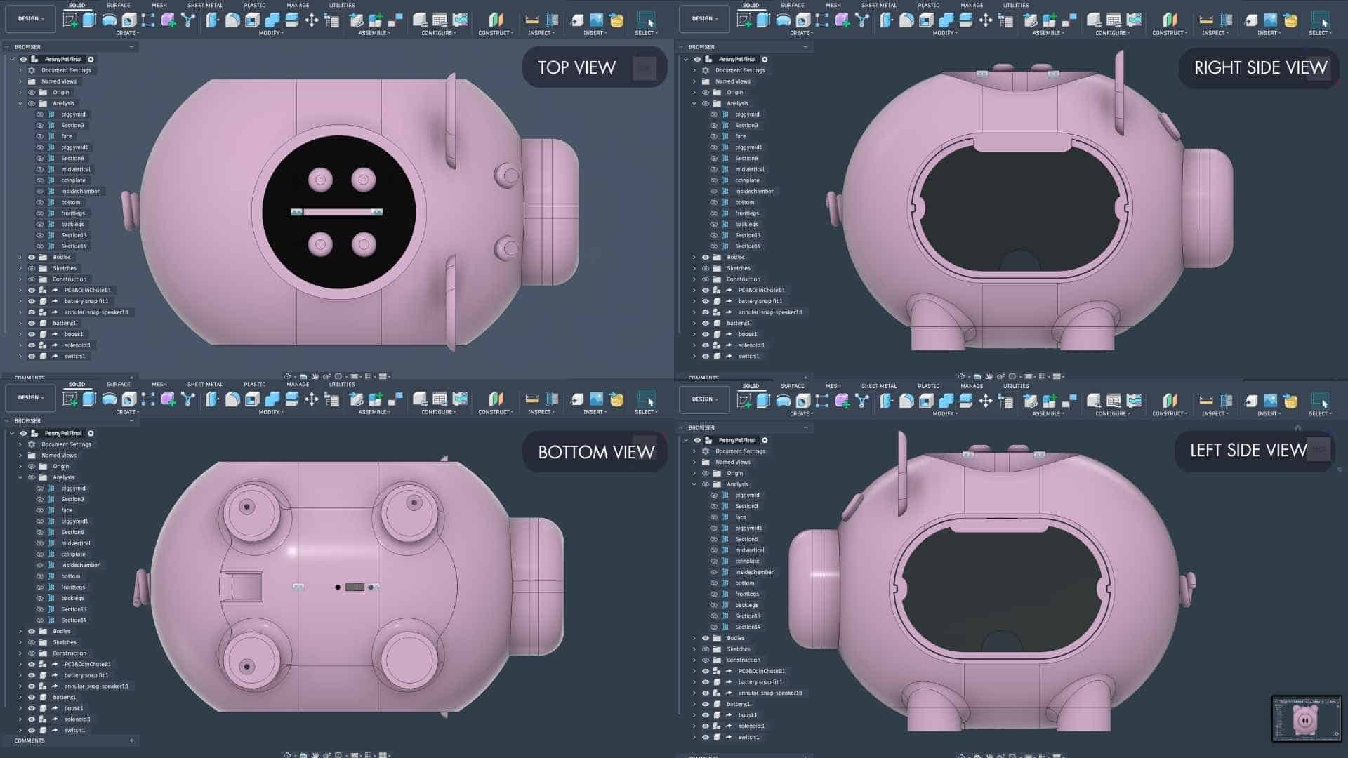
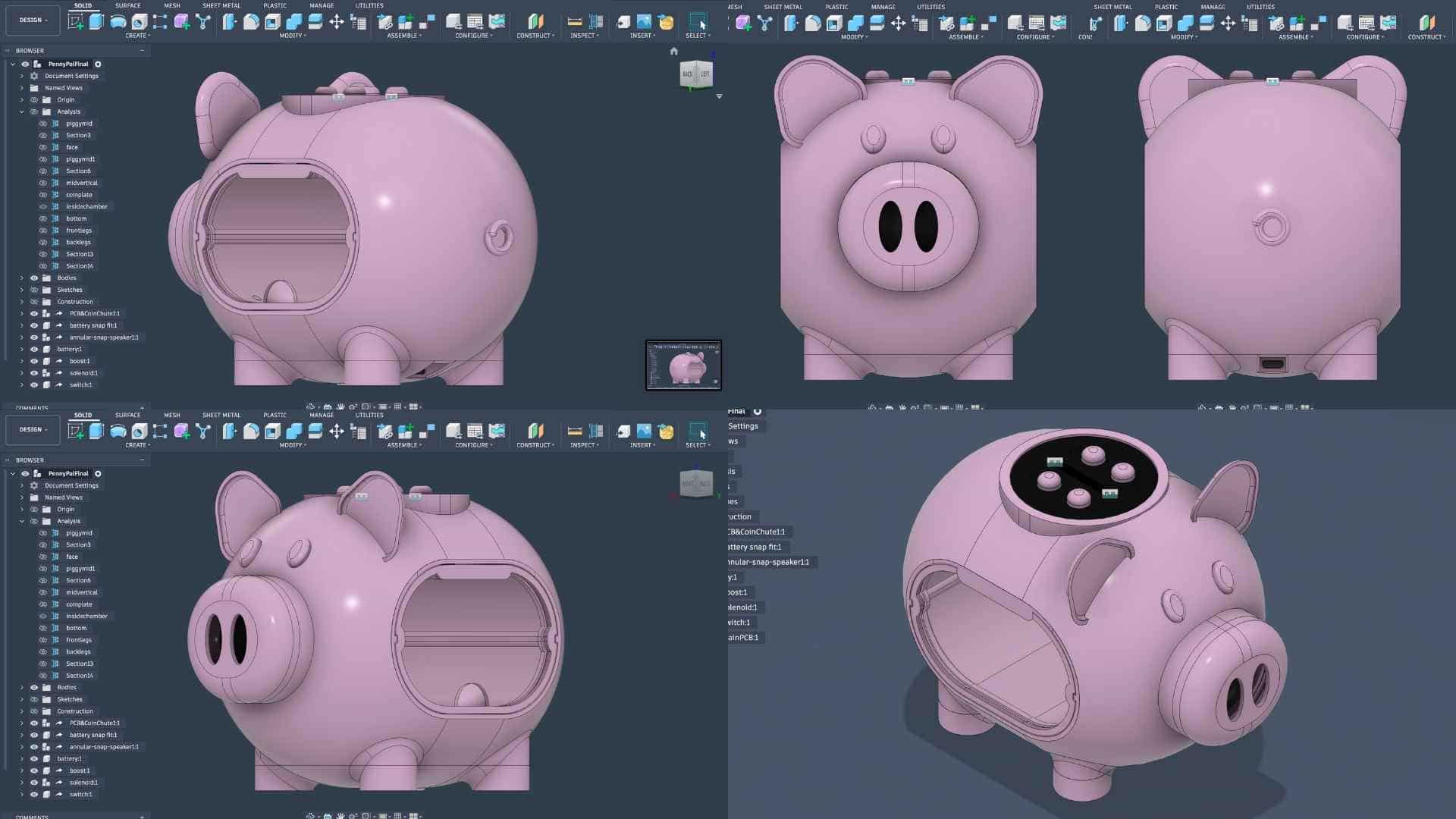
As the design matured, the model gradually transformed into a complete digital representation of the system. The speaker enclosure, coin chute, solenoid locking mechanisms, removable coin drawer, main PCB, breakout board, wiring clearances, mounting features, battery compartment, and structural elements were all integrated into a single assembly. Each iteration revealed new constraints and opportunities for improvement, leading to multiple rounds of refinement.
The following screenshots document that process. Together, they show how the various subsystems were arranged, how space was allocated for electronics and wiring, how the mechanisms were incorporated into the enclosure, and how the final product architecture emerged through successive design decisions.
More than anything, these models served as a bridge between concept and fabrication. They allowed me to identify potential problems before printing parts, evaluate assembly sequences, and ensure that the mechanical, electronic, and user-facing aspects of the project could coexist within a single integrated system.
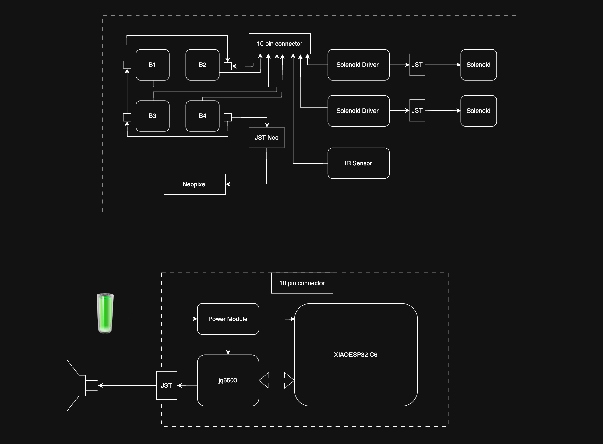
Block Diagram (draw.io)
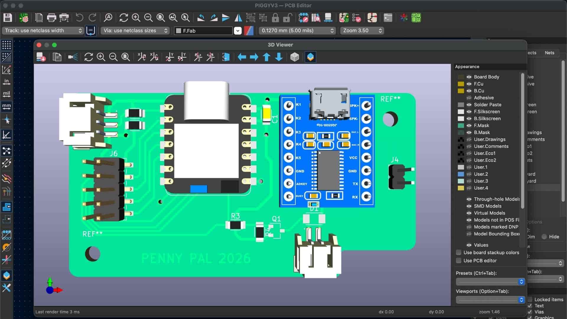
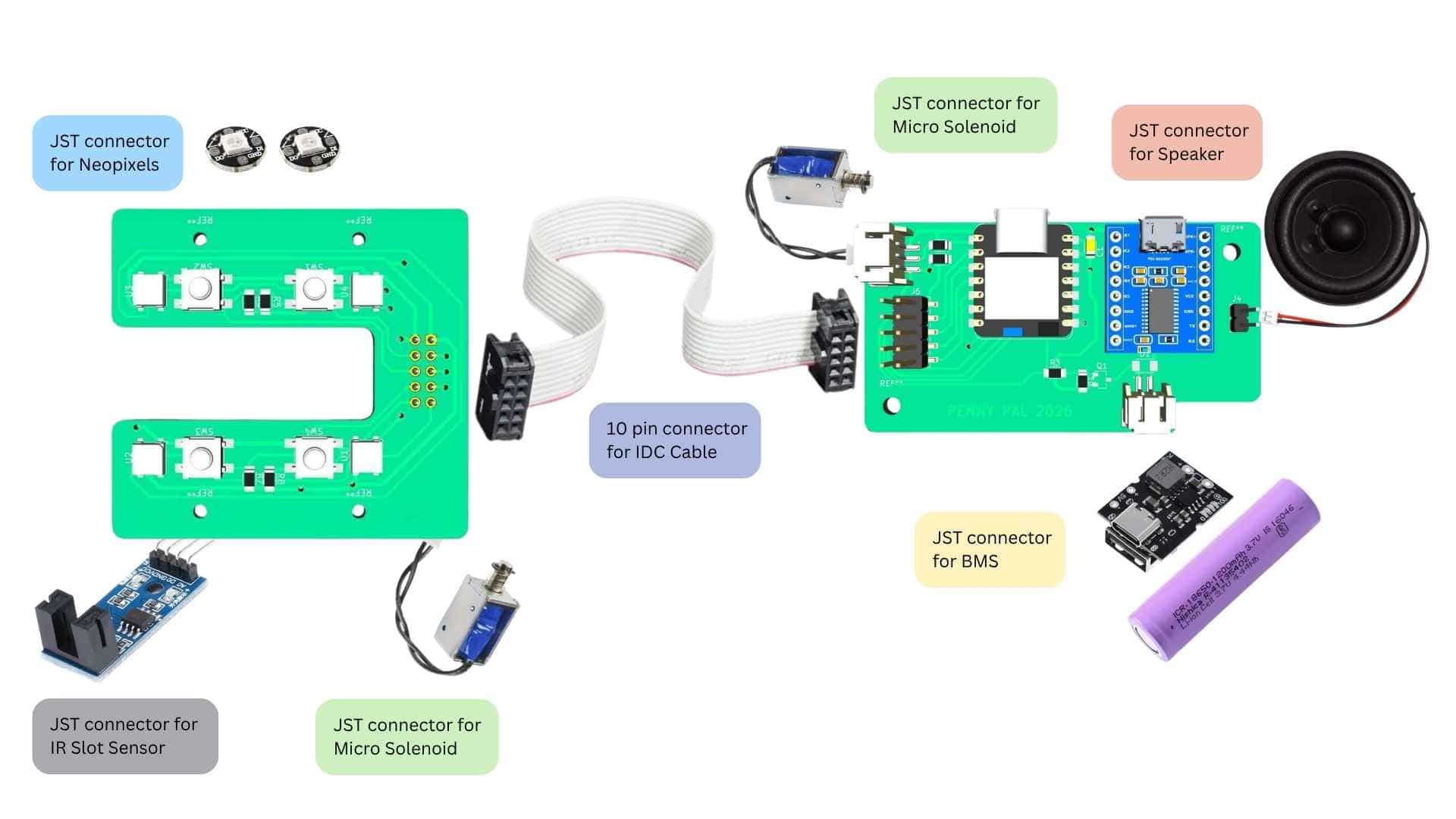
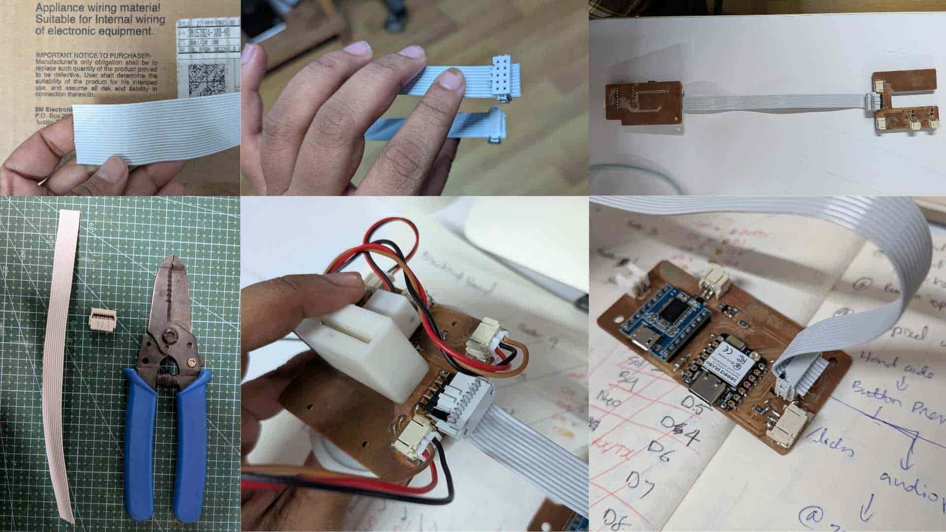
PCB Wiring Harness
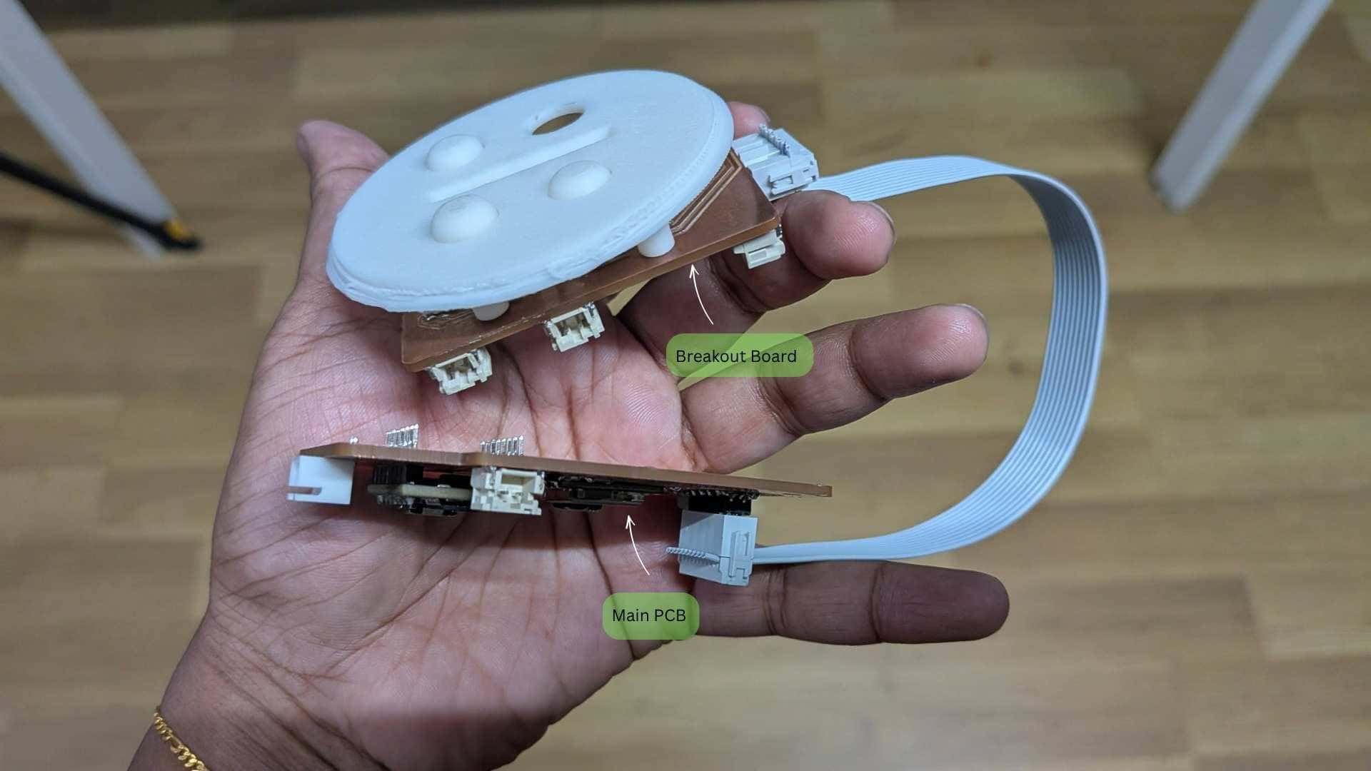
To keep the wiring clean and compact, I divided the electronics into two PCBs: a main PCB and a breakout board, connected using a 10-pin ribbon cable.
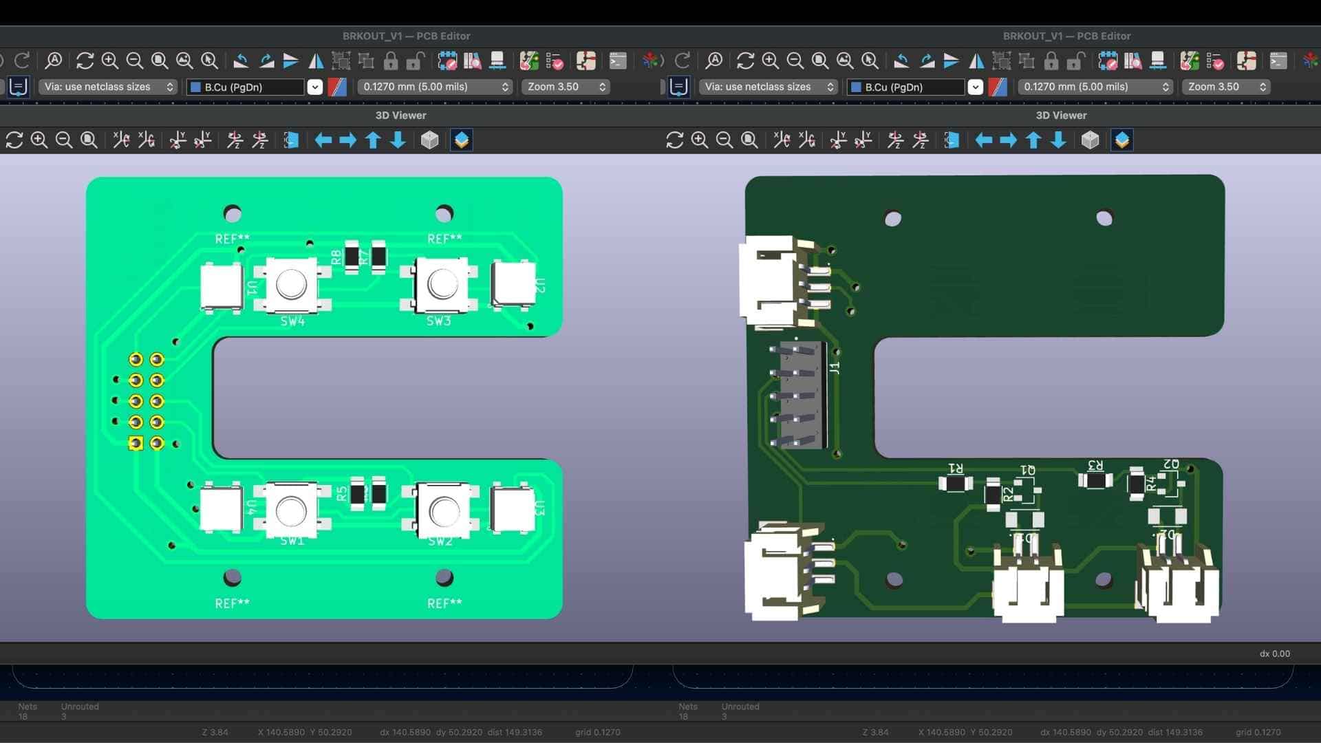
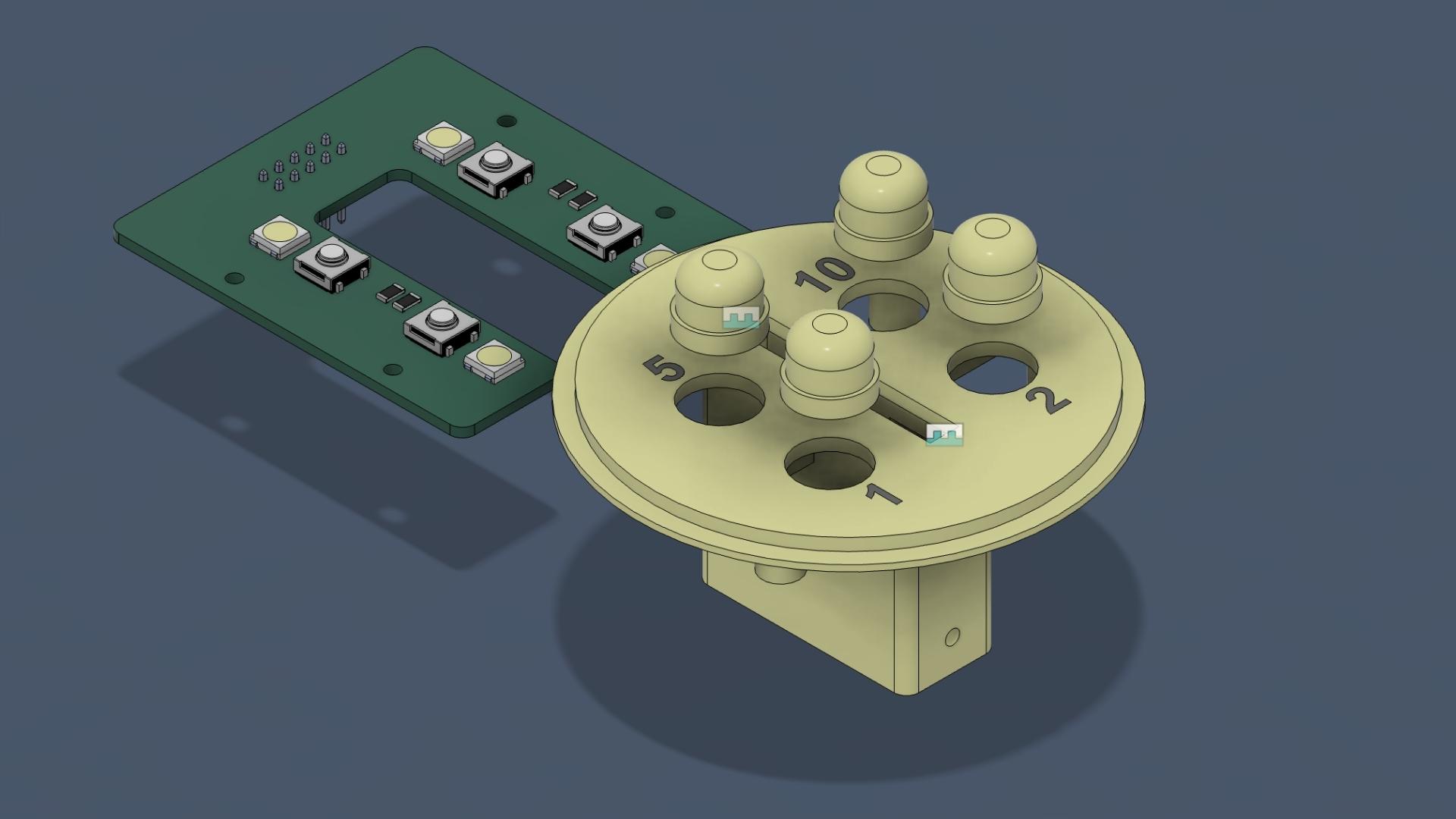
The breakout board was integrated into the coin chute assembly and housed all the nearby components, including the IR break-beam sensor, four denomination buttons, NeoPixels, and the solenoid connection. Instead of running individual wires from each of these components to the main PCB, all the signals were combined into a single ribbon cable. This reduced wiring clutter, simplified assembly, and made the electronics easier to disconnect and maintain.
The ribbon cable is routed through the back of Penny Pal, passing between the coin chamber and the tail. This provided a dedicated wiring path that kept the cable away from moving parts and prevented it from interfering with the coin storage area.
Overall, this modular approach resulted in a cleaner internal layout, easier assembly, and a more compact design.
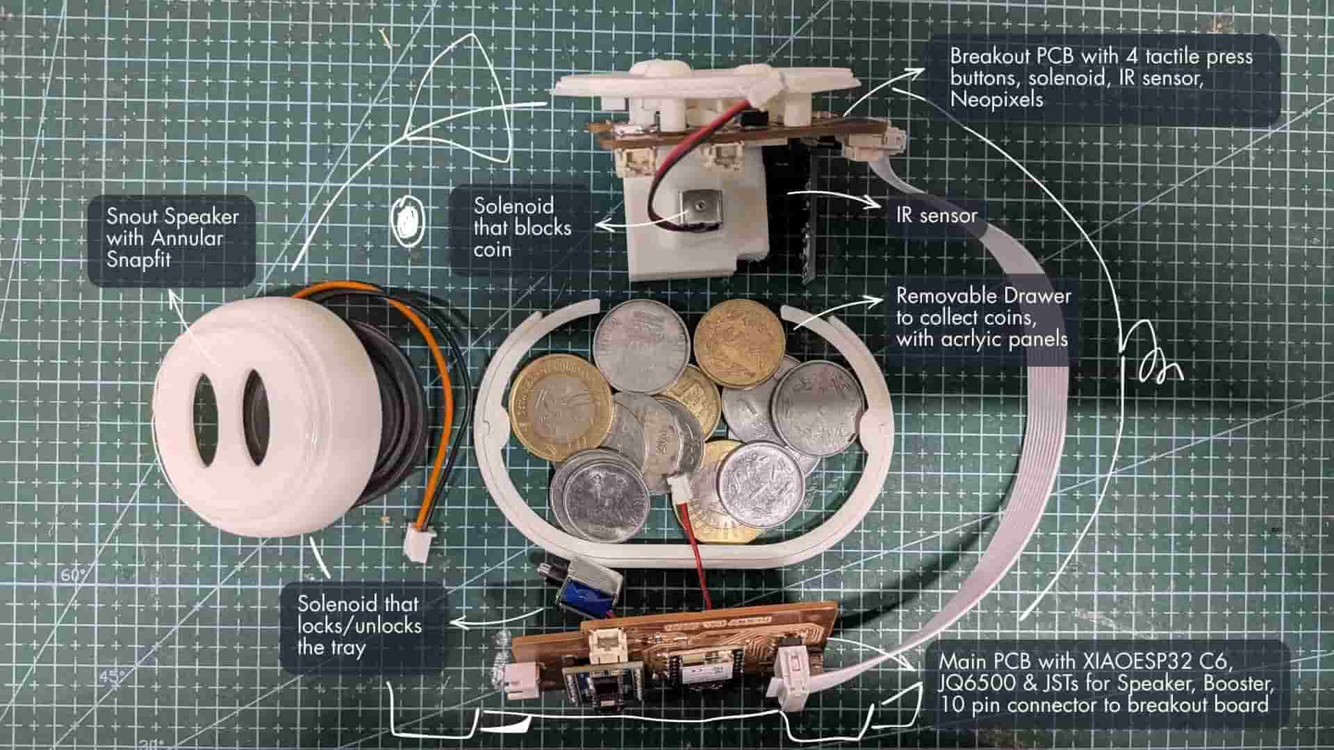
My System Integration Snapshot
While designing Penny Pal, I often felt like I was studying the anatomy of a pig before it was born.
The enclosure was split apart. Internal systems were exposed. Components were spread across the cutting mat as I tried to understand how everything might coexist inside a limited volume.
A post-mortem before birth.
Every prototype taught something.
Some taught what worked.
Many taught what did not.
Holding a printed part often revealed more than hours spent staring at a screen. The proportions felt different. The scale felt different. The accessibility felt different. I worried the pig might become too large, but it eventually settled into a size that felt comfortable to hold.
If I had to choose a single image that captures the essence of Penny Pal, it would be this one.
Power Module
Penny Pal is powered by a rechargeable 3.7V Li-ion battery. To safely manage charging and battery protection, I used a BMS (Battery Management System) module along with a USB Type-C charging board. The battery was insulated using Kapton tape to prevent accidental short circuits while keeping the assembly compact.
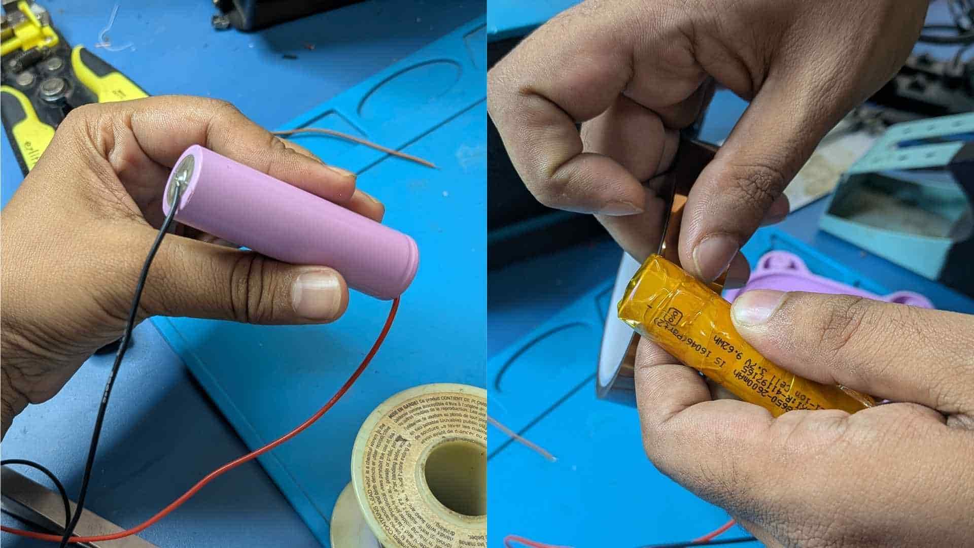
A boost converter steps the battery voltage up to the required operating voltage for the electronics, while a toggle switch acts as the main power switch. The entire power module connects to the main PCB using JST connectors, making it easy to assemble, disconnect, and replace if required.
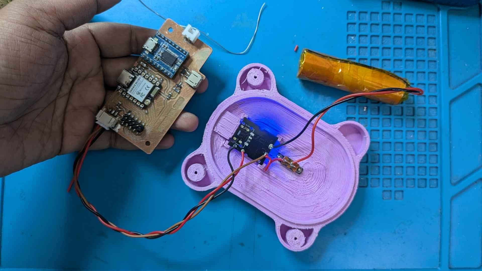
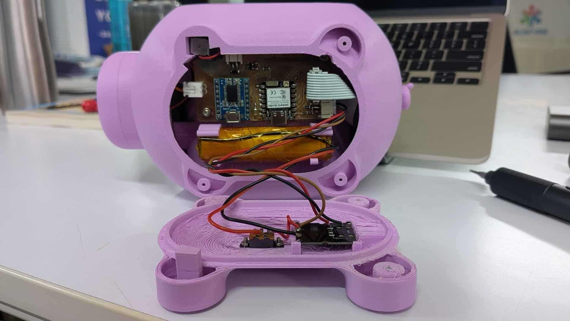
This is the project's skeleton, the collection of subsystems that eventually come together to form the final product. Looking at it now, I see both a record of what had already been achieved and a reminder of everything that still needed to be figured out.
At this point, the major building blocks existed. The main PCB had been designed, a breakout board brought together the user inputs and sensors, the speaker assembly had taken shape, the coin-blocking mechanism was functional, and the collection drawer and locking system were beginning to find their place within the enclosure. For the first time, the electronics, mechanics, and user interaction elements could be laid out together and viewed as parts of a single system.
Click the image to view the next one →
What makes these images particularly important is that it also exposes the remaining challenges. None of these parts had been fully integrated yet. Wiring routes, mounting features, internal clearances, assembly sequence, and enclosure constraints were still unresolved. The project had moved beyond isolated component testing, but it had not yet become a complete product.
In many ways, these photographs represents a checkpoint between concept and reality. It is a snapshot of the moment when Penny Pal stopped being a collection of diagrams, sketches, and ideas, and started becoming a physical system with real components, real constraints, and real engineering decisions.
Everything that followed, the enclosure refinements, mechanism testing, mounting strategies, and final assembly was built upon the foundation visible in these images.
The Story Behind the Integration
What follows is a walkthrough of the final integrated system, but getting here was anything but straightforward. Every component, mechanism, PCB, mounting feature, and enclosure detail visible in these models is the result of weeks of experimentation, redesigns, unexpected failures, and countless small decisions.
If you're interested in the full journey, from the first sketches and prototypes to the final implementation, I recommend visiting the Project Development page before continuing. It provides the missing chapters that explain how Penny Pal gradually evolved into the system shown below.
Explore Project Development →Integrated System Design (Updates from the final weeks)
The piggy bank started as a simple shell to hold the electronics. Very quickly, it became clear that the enclosure itself was becoming a project of its own.
Every new component came with a question:
Where does it go?
How do I assemble it?
How do I access it later?
What happens when something needs to be replaced?
The final design is the result of answering those questions one by one.
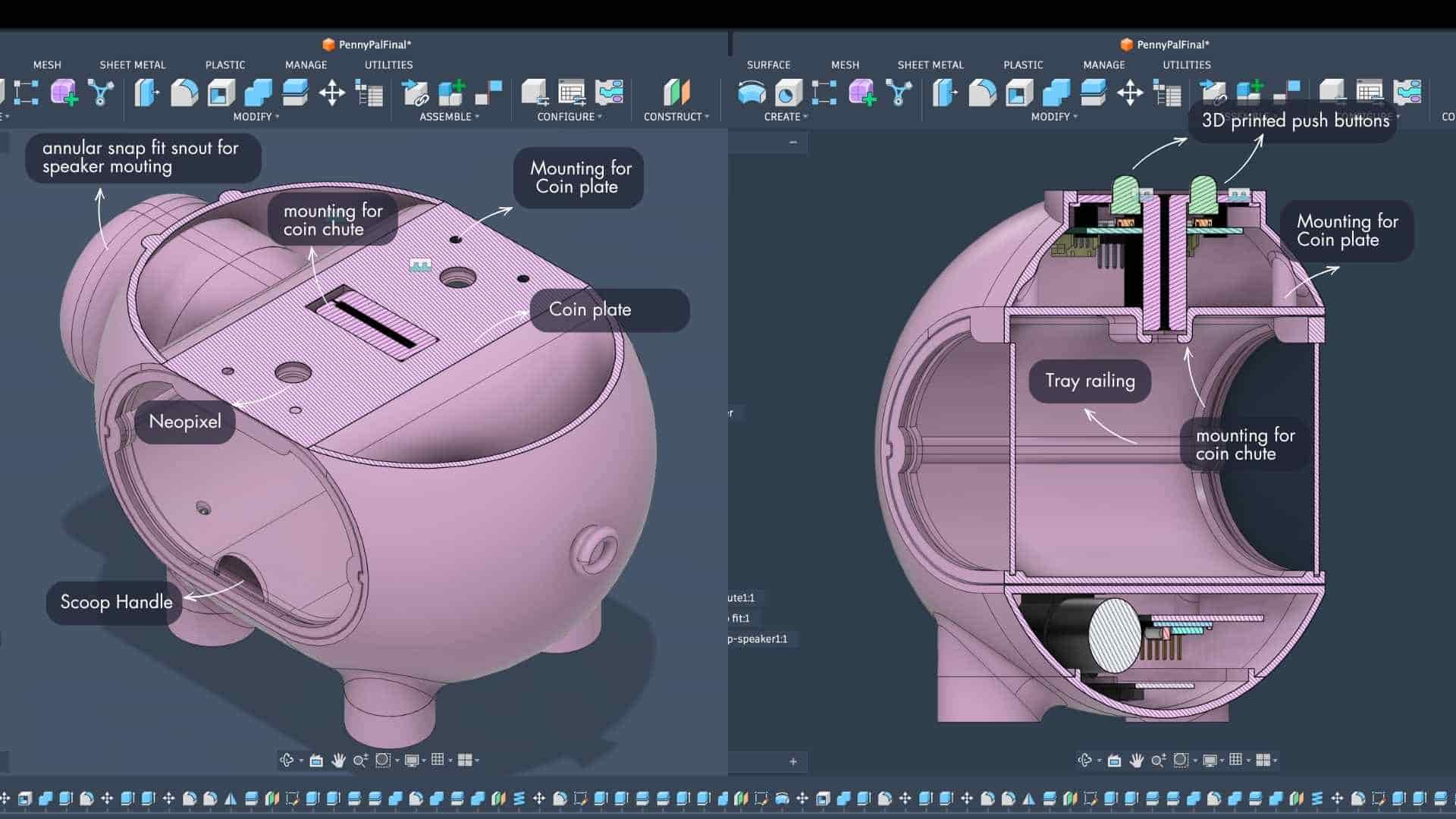
Coin Chute and Coin Plate
The coin chute assembly sits at the top of the enclosure and houses the breakout PCB, buttons, NeoPixels, and sensing components.
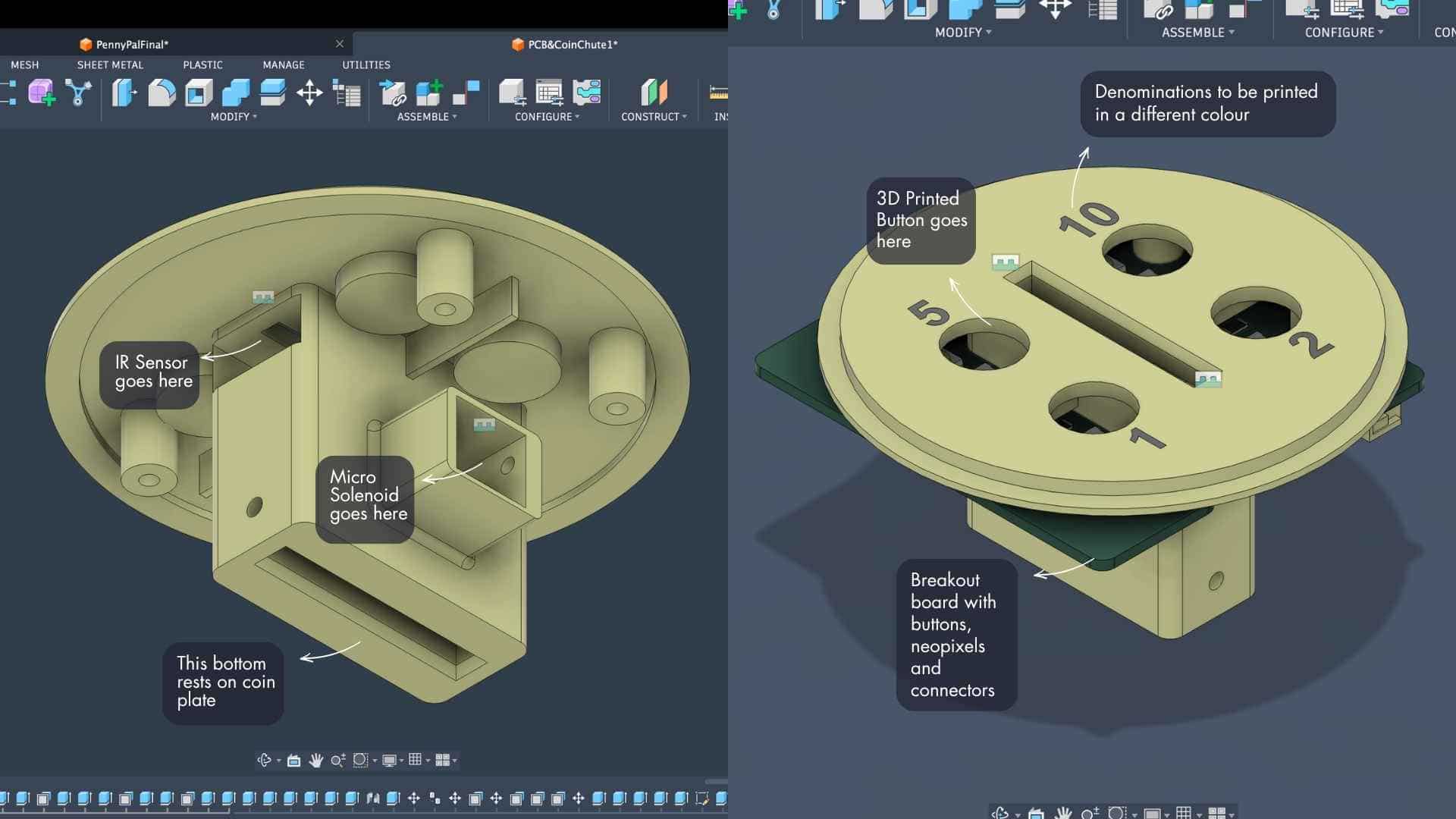
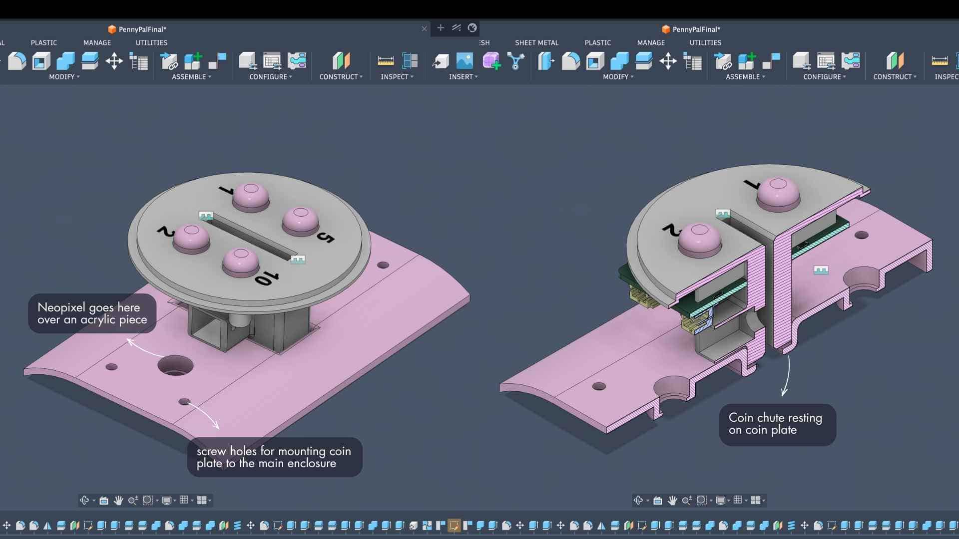
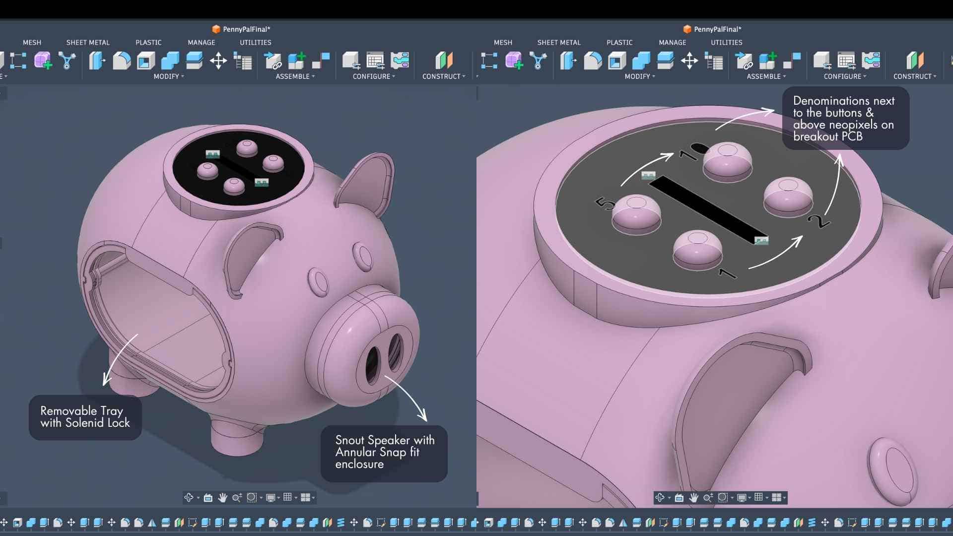
The coin plate does more than hold the chute. It is effectively the roof of the collection chamber. Once mounted, it keeps the chute assembly in place while also locking the tray compartment within the enclosure.
This meant a single part could serve multiple purposes instead of introducing additional brackets or supports.
PCB Placement and Cable Routing
The breakout PCB lives inside the coin chute assembly, while the main PCB sits at the bottom of the enclosure.
Both boards are connected using a 10-wire ribbon cable routed along the back side of the piggy bank. During the design process, I intentionally kept this cable path away from moving parts and assembly interfaces. It passes through a relatively undisturbed area that can be seen in the side section views.
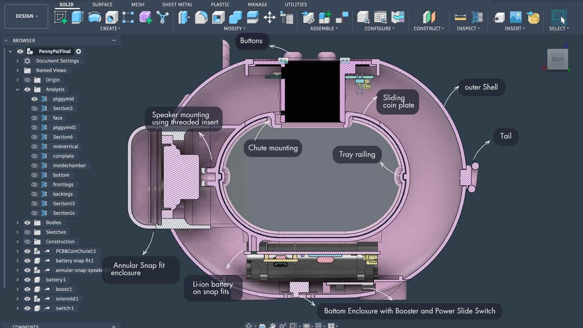
The cable stays protected, does not interfere with the tray or chute mechanism, and remains accessible if anything needs to be serviced later.
NeoPixels and Visual Feedback
The NeoPixels are mounted beneath the coin plate using acrylic inserts. Rather than exposing the LEDs directly, the light is allowed to diffuse through the acrylic and into the collection chamber. This creates a softer visual feedback effect while showing the user's savings progress and current total.
An unexpected benefit was that the tray itself becomes part of the lighting experience, turning the coin chamber into a glowing indicator rather than just a storage compartment.
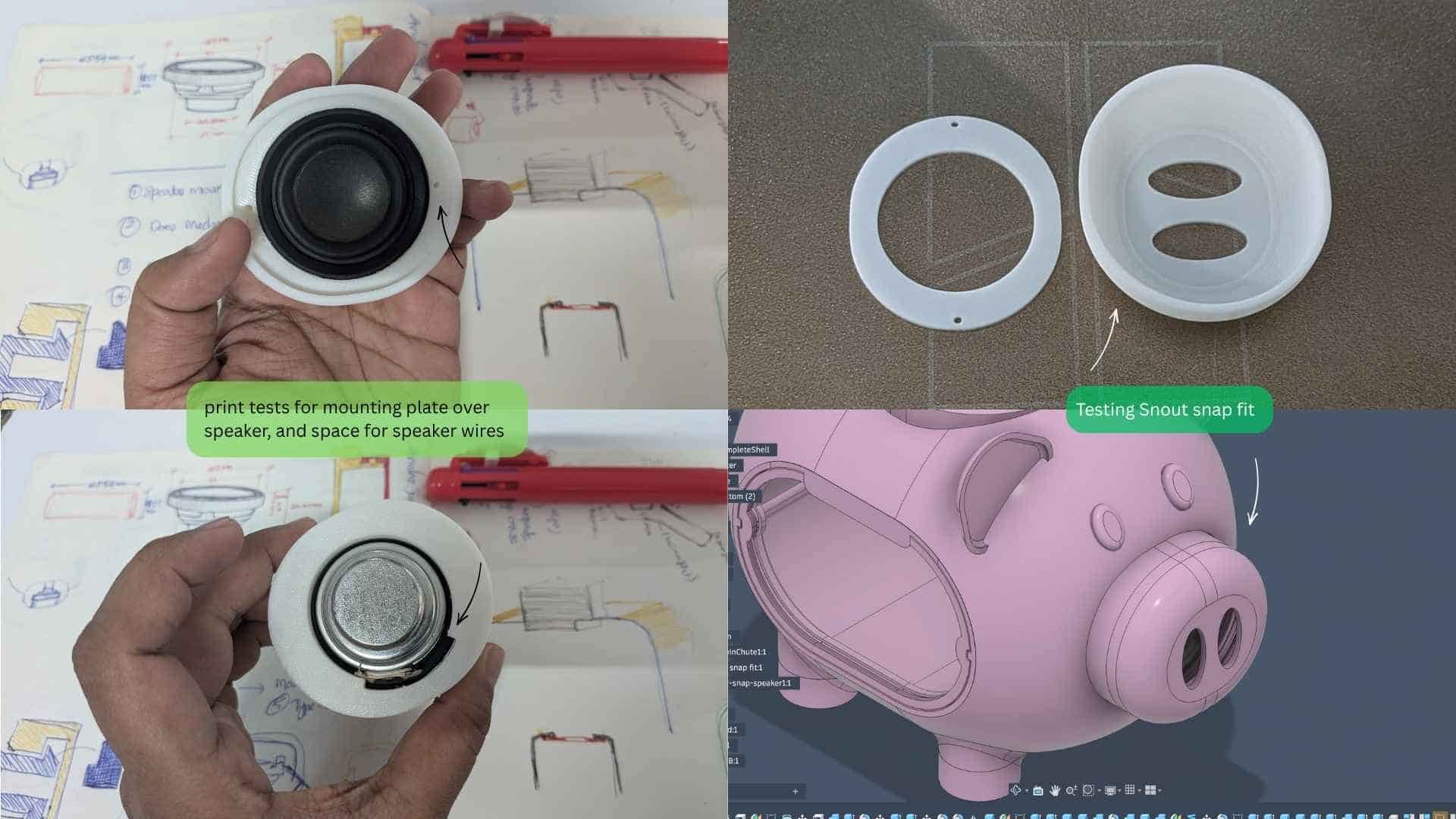
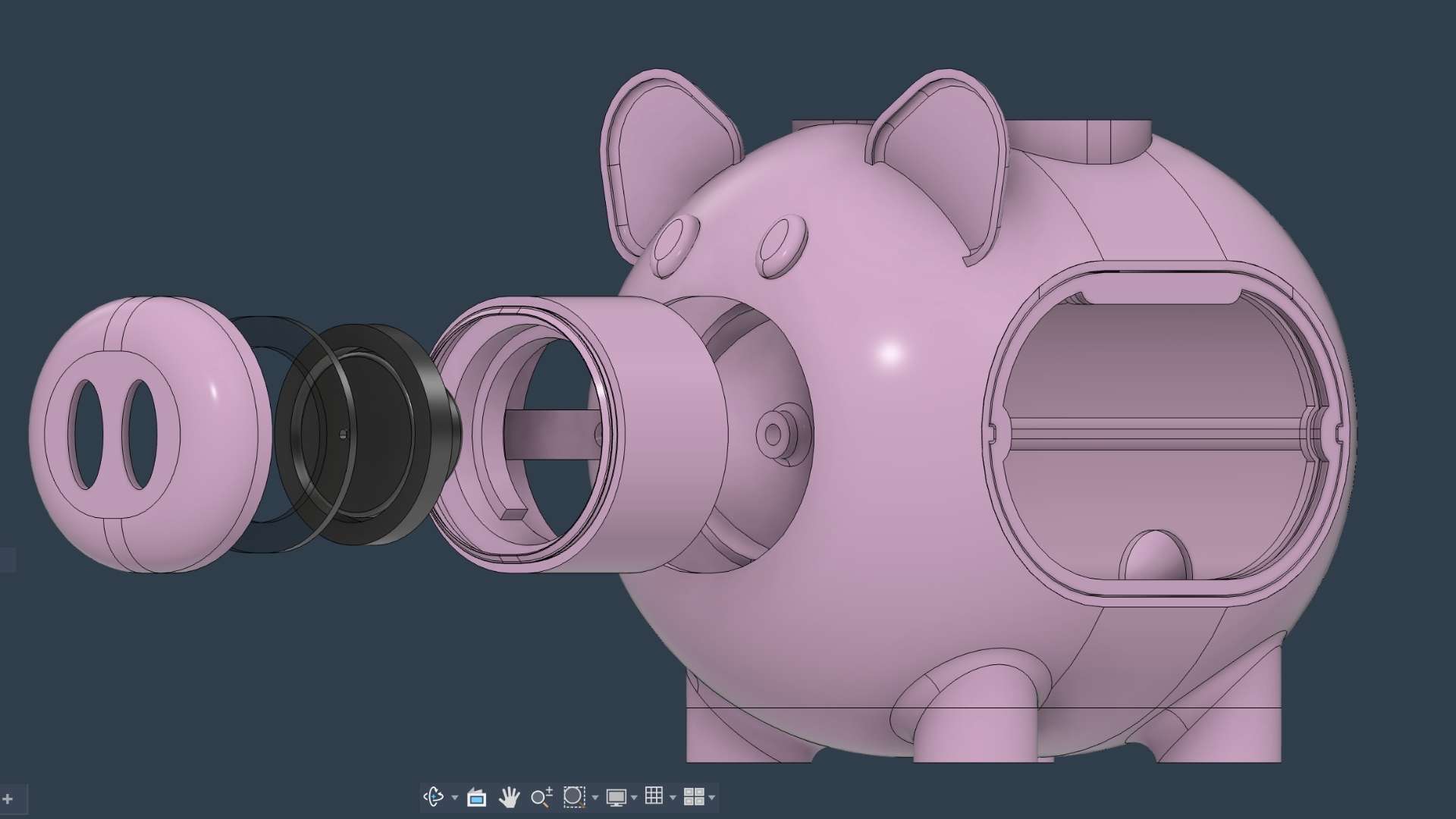
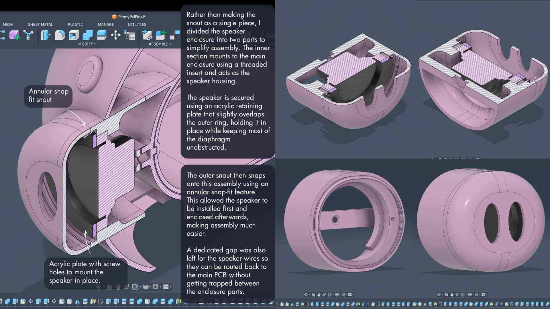
Speaker Integration
The speaker is mounted inside the snout using threaded inserts and an annular snap-fit enclosure.
Placing the speaker inside the snout felt natural from both a functional and visual perspective. The sound is projected towards the user, while the speaker remains integrated into the character of the piggy bank rather than looking like an added electronic component.
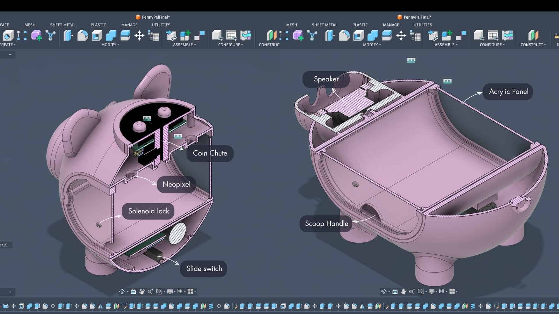
The Tray Compartment
The front tray acts as the coin collection compartment. It uses acrylic panels on both the front and back, making the drawer lightweight while still letting the user see the collected coins.
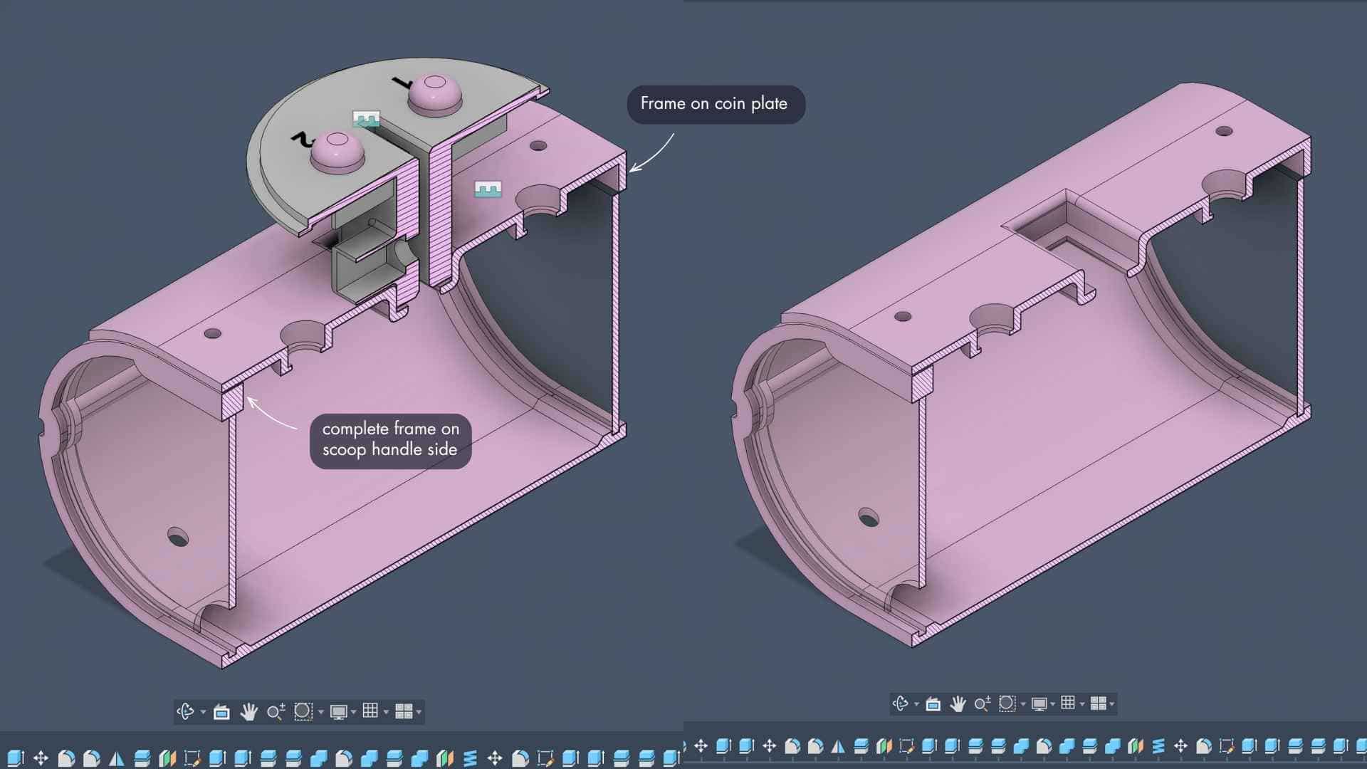
My first thought was to add a handle to pull the tray out. The more I looked at it, the more it bothered me. A handle would sit on one side of the piggy bank and immediately break the symmetry of the design.
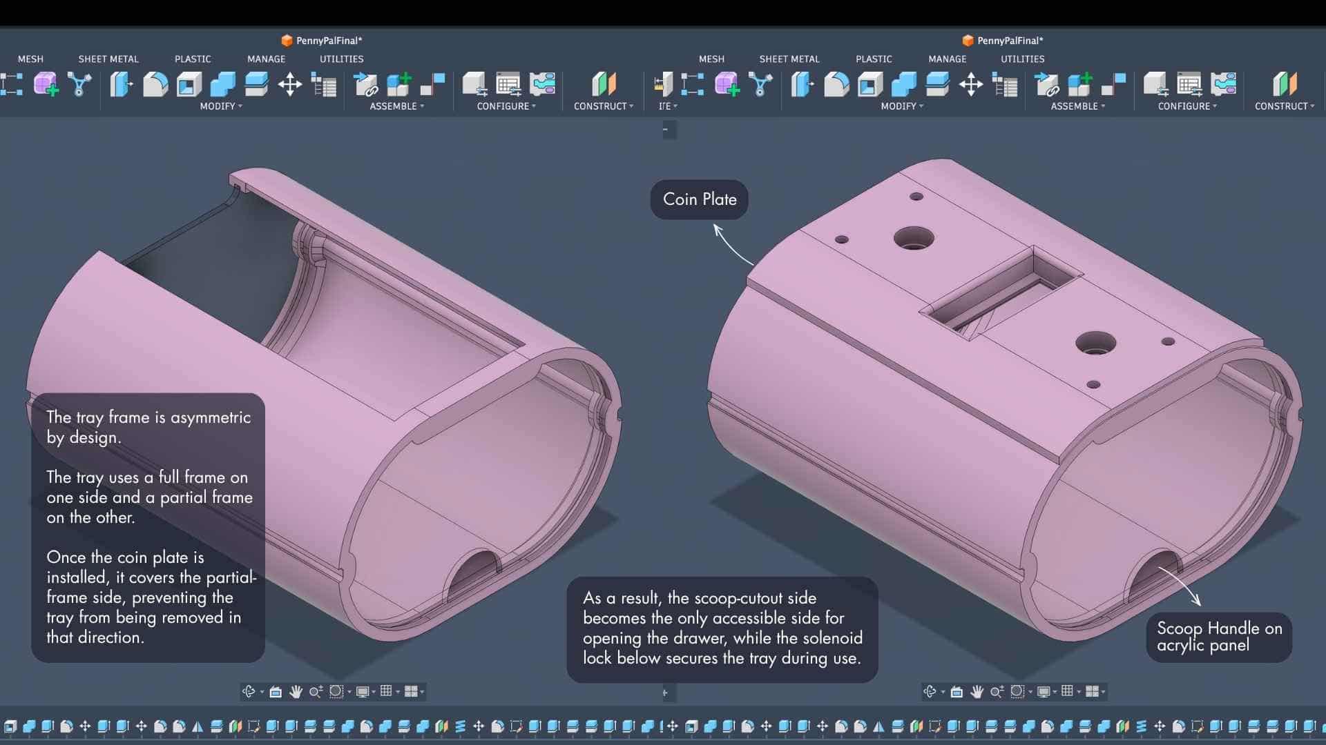
That led to the finger scoop cutout on the acrylic panel. Instead of adding something that sticks out, material is removed to create a grip point. The scoop stays flush with the overall form, keeps the front clean, and avoids introducing an awkward asymmetry just to solve the problem of opening the drawer.
Battery and Power System
The lower enclosure houses the Li-ion battery, booster module, power switch, and main PCB.
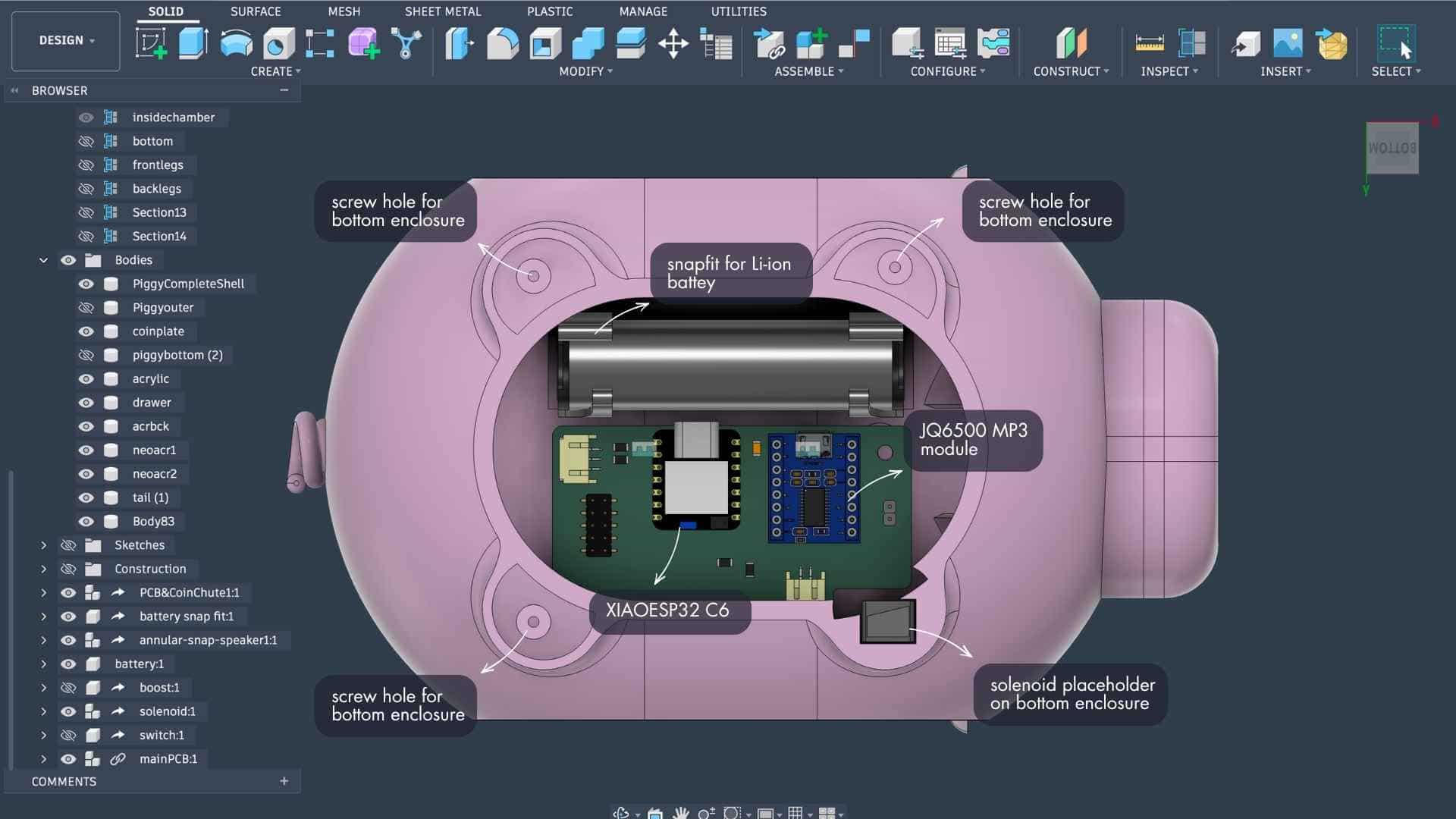
The battery is retained using integrated snap-fit features, removing the need for a separate battery holder. The power switch and charging access are located on the underside, keeping the visible surfaces of the piggy bank uncluttered.
Feet and Stability
The feet are attached using recessed screw holes so the fasteners remain hidden after assembly.
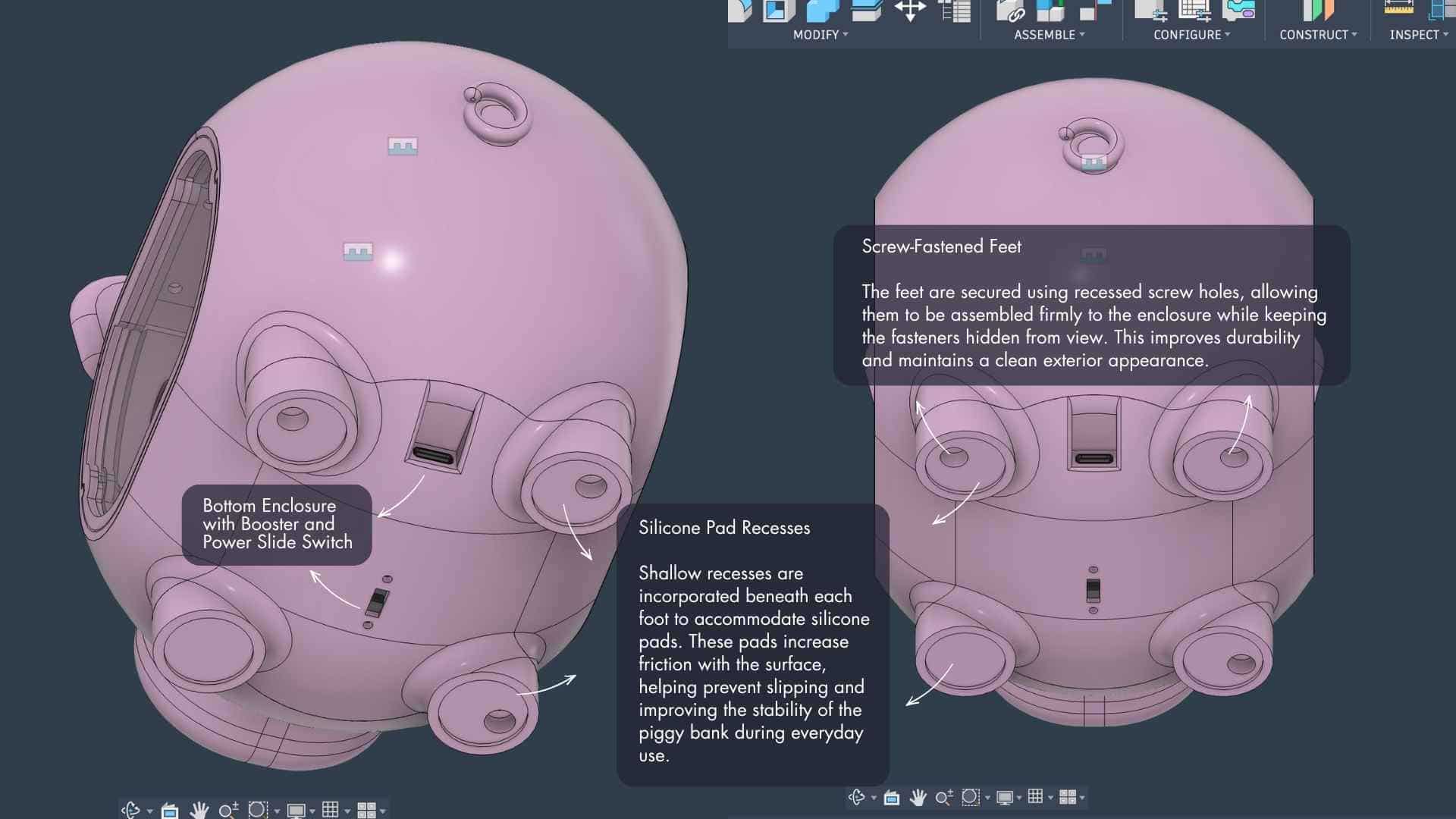
Since the piggy bank will likely be handled frequently, shallow recesses were added beneath each foot to accommodate silicone pads. These pads improve grip on smooth surfaces and help prevent the enclosure from sliding around during use.
Section Views
The section views became one of the most useful design tools during development.
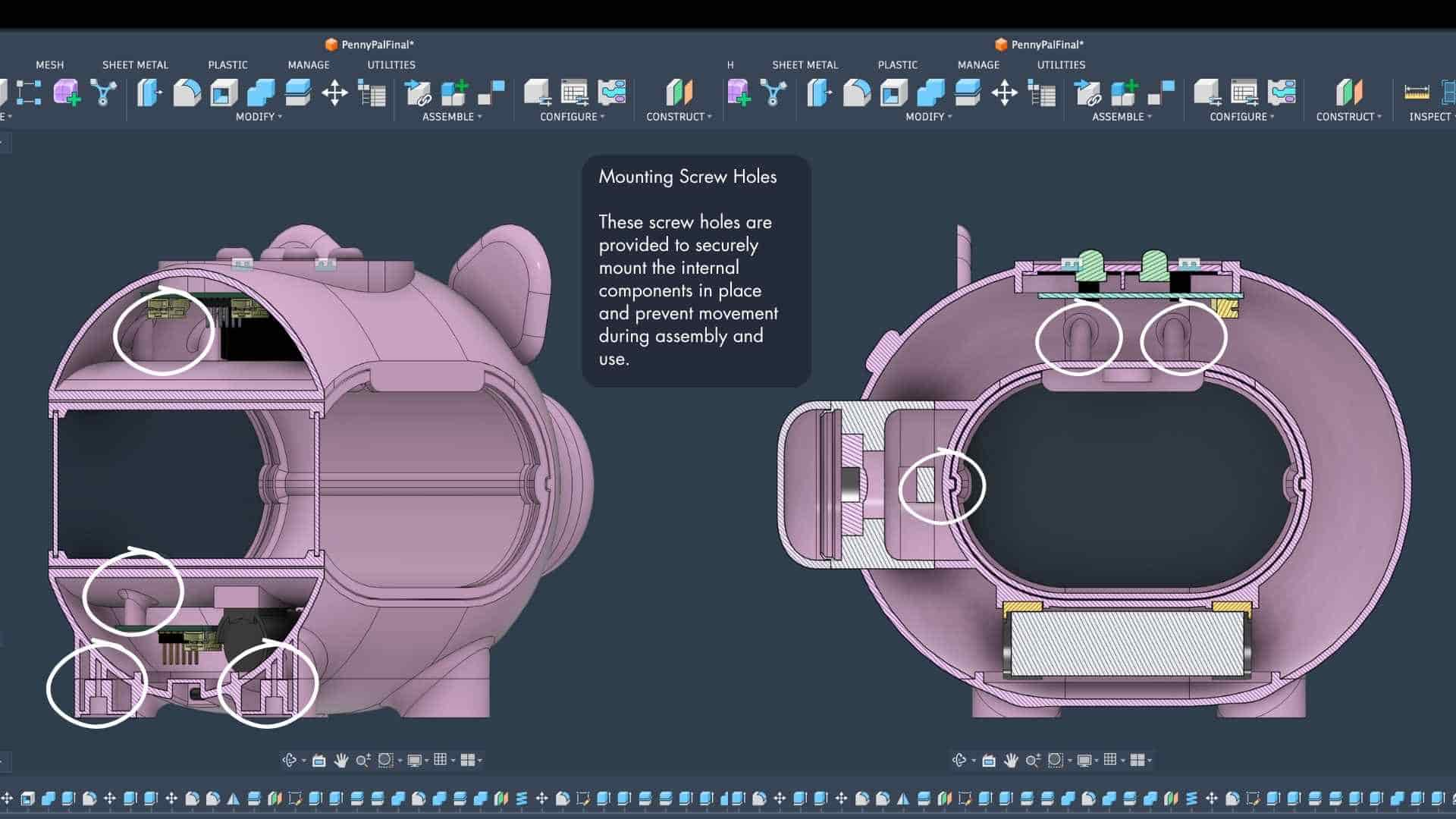
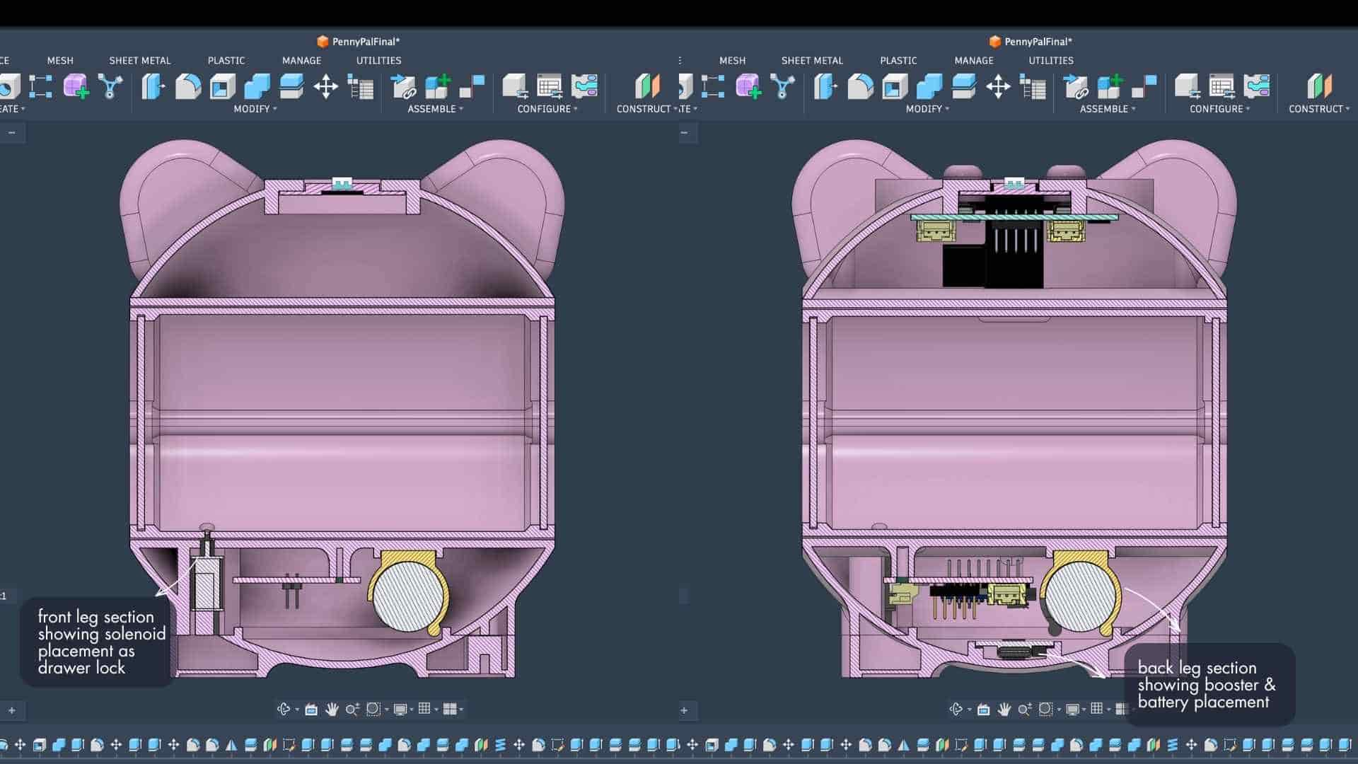
They helped verify clearances, cable routing, component placement, tray movement, speaker mounting, battery access, and assembly order. More importantly, they helped reveal problems that were not obvious from the exterior model.
Many small design decisions only became visible once the enclosure was cut open virtually and examined from the inside.
Bringing Penny Pal to Life
Looking back, Penny Pal did not emerge from a single idea or a single CAD file.
It emerged from hundreds of small decisions.
From sketching and modelling.
From measuring, printing, testing, assembling, disassembling, and rebuilding.
From moments when nothing made sense.
Connecting to Mobile App (Firebase + Kodular)
Application & Interfaces
The mobile application was developed using Kodular and Firebase, enabling Penny Pal to communicate wirelessly over Wi-Fi. Users can set a savings goal, while the app displays the current total and progress percentage in real time whenever a coin is inserted.
Explore Week 15 documentation: Interface and Application Programming →Thinking Through Assembly
One of the things I spent a lot of time on was not just designing the parts, but figuring out the order in which they would actually go together.
The tray opening became the primary assembly access point.
First, the coin chute mechanism is inserted through the tray opening. Once it is in position, the coin plate is mounted, securing the chute assembly and forming the top of the chamber.
The tray was slide into place.
The main PCB is then installed and connected to the breakout PCB through the ribbon cable. After that, the speaker assembly, battery, and remaining electronics are mounted. The booster module is attached to the bottom enclosure, and the entire bottom assembly is secured to the main shell.
Working through this assembly sequence early helped expose potential conflicts before fabrication and ensured that every component could actually be installed in the real world, not just inside a CAD model. The final object is only the visible part of the project.
The real project lives in the iterations that came before it.
Every sketch, prototype, redesign, moment of frustration, and small breakthrough is embedded somewhere inside Penny Pal. The final assembly is simply where all those decisions became visible.