Week 14: Molding and Casting
Group Assignment:
Review the safety data sheets for each of your molding and casting materials,
then make and compare test casts with each of them.
Compare mold making processes
Group Assignment Reflection
As part of the group assignment, we reviewed the materials available in the lab and went through their safety information, mixing ratios, curing times, and handling requirements. The materials we worked with were Aditya Silicone Rubber RTV - 1010, Aditya Ultra Clear Cast Epoxy - 37, and Mould Releasing Spray 1083.
We also made test molds and casts to compare how the different materials behave. I learned how important accurate measurement, thorough mixing, and vacuum degassing are for achieving good results. Aditya Silicone Rubber RTV - 1010 produced flexible molds with good detail capture and Aditya Ultra Clear Cast Epoxy - 37 created clear casts but required extra care to avoid trapped air bubbles. Mould Releasing Spray helped with easy demolding and prevented the cast from sticking to the mold.
| Material | Purpose | Mixing Ratio | Working Time | Curing Time | Hardness | Notes |
|---|---|---|---|---|---|---|
| Aditya Silicone Rubber RTV – 1010 | Mold Making | Silicone + 2.5–3% Hardener | 8–10 min | 12–24 hrs | Shore A 10 | Flexible mold material with excellent detail capture and easy demolding. |
| Aditya Ultra Clear Cast Epoxy – 37 | Casting Material | Part A : Part B = 100 : 50 | Moderate | 12–24 hrs* | Rigid after cure | Transparent, low-viscosity resin that produces clear casts with a smooth finish. |
* Curing time may vary depending on the volume of resin being cast and ambient conditions.
This activity helped me understand the differences between mold-making materials and casting materials, along with the practical workflow involved in molding and casting before moving on to my individual assignment. It also helped me understand the importance of material selection-typically using a harder mold to cast softer materials for easier demolding, and using flexible mold materials such as silicone when casting harder materials with complex geometries or undercuts, allowing the finished part to be removed without damage.
For more details, visit the group assignment page.
Individual Assignment:
Design a mold around the process you'll be using, produce it with a smooth surface finish that does not show the production process toolpath, and use it to cast parts
Extra credit: use more then two mold parts
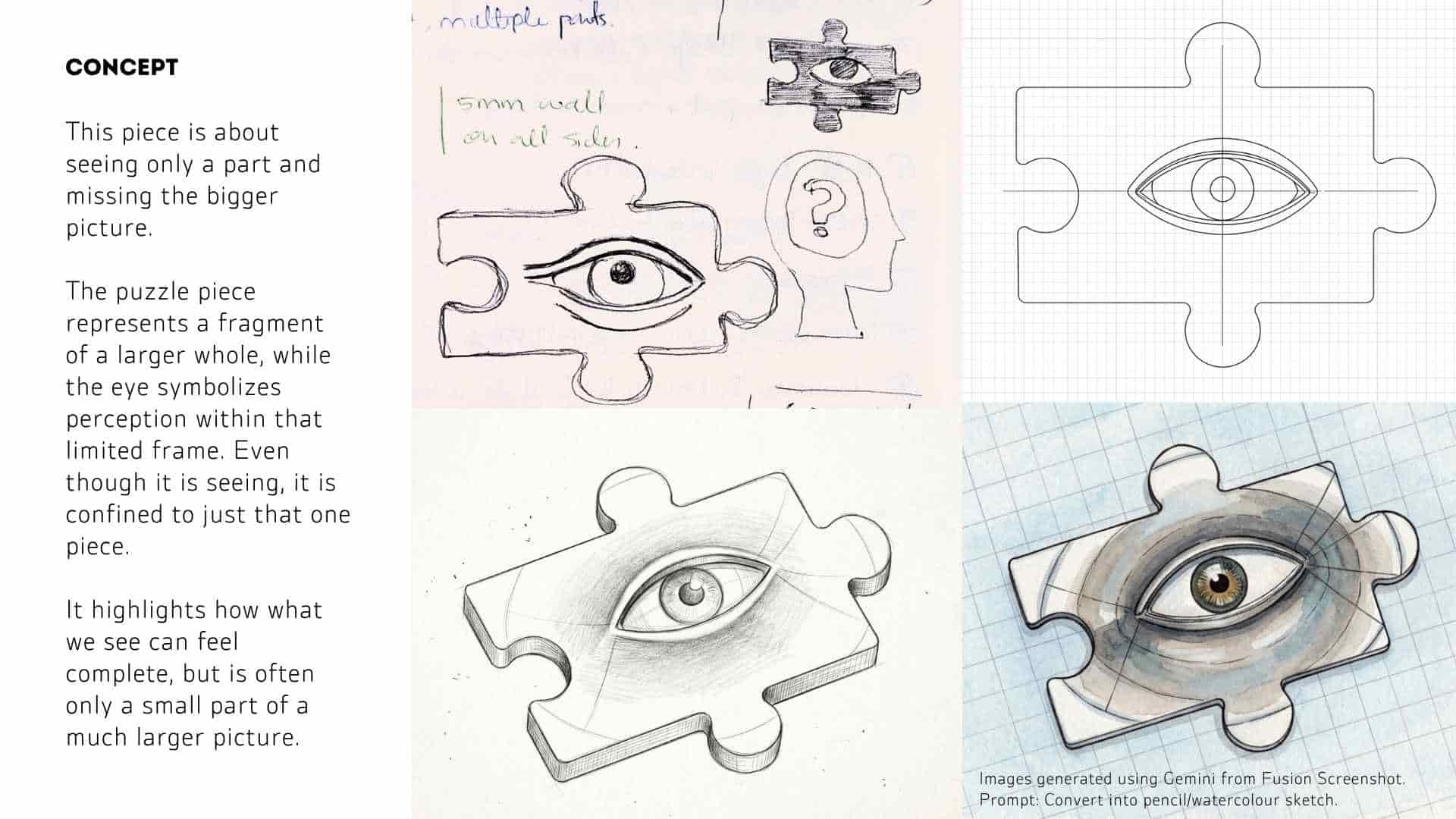
Concept to CAD Model
Stock Definition + Safe Boundary
I started by defining the working area based on the dimensions of the machinable wax block provided. Since milling close to the edges can lead to chipping or incomplete cuts, I created an internal offset boundary. This ensured a safety margin around the geometry, allowing sufficient space for tool movement and preventing edge failures during machining.
Puzzle Geometry Sketch
Within this safe boundary, I sketched the puzzle piece profile. The outline was constructed with attention to symmetry and smooth curvature so that the interlocking edges remain consistent. Keeping the geometry controlled at this stage was important, as any irregularities would directly affect both machining quality and the final cast.
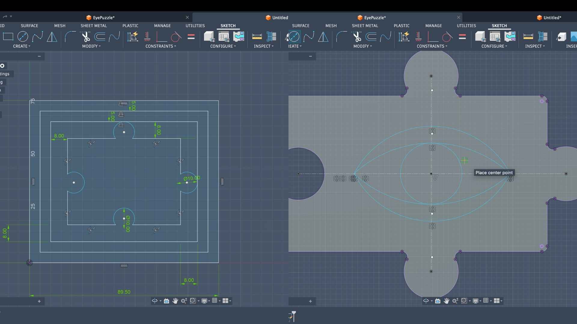
Eye Construction (2D Sketch)
After establishing the base shape, I developed the eye geometry inside the puzzle. The eyelid curves were created using 3-point arcs, which allowed precise control over curvature and ensured that both sides remained symmetrical about the central axis. This step defined the key visual element while maintaining alignment with the overall form.
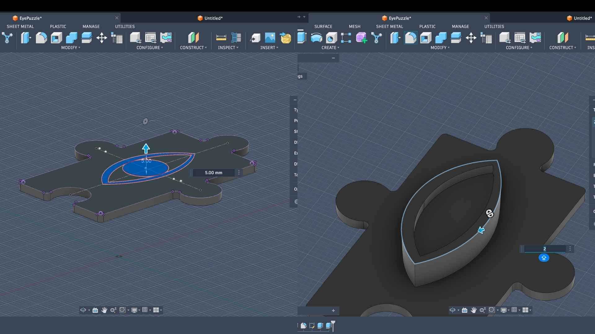
Base Extrusion
Once the sketches were complete, I extruded the puzzle profile to form the primary solid body. This established the base thickness of the model, which directly corresponds to the depth of material that will be milled from the wax block.
Eyelid Extrusion + Primary Form Development
The eyelid geometry was then extruded as a secondary feature on top of the base surface. This introduced a layered relief, beginning to define how the eye would appear in three dimensions when translated into the mold and final cast.
Edge Filleting (Machining Consideration)
At this stage, I applied fillets to all sharp external and internal edges. Sharp corners are difficult for CNC tools to reproduce due to tool diameter limitations, and they can also cause abrupt toolpath changes. By softening these edges, the geometry becomes more compatible with the milling process and results in a smoother surface finish.
Surface Blending (Eyelid to Base Transition)
Beyond basic edge filleting, I introduced additional fillets between the eyelid and the puzzle surface. This was done to create a smooth, continuous transition rather than a stepped or abrupt junction. The goal here was to achieve a more organic form that would translate well both in the mold and in the final resin cast.
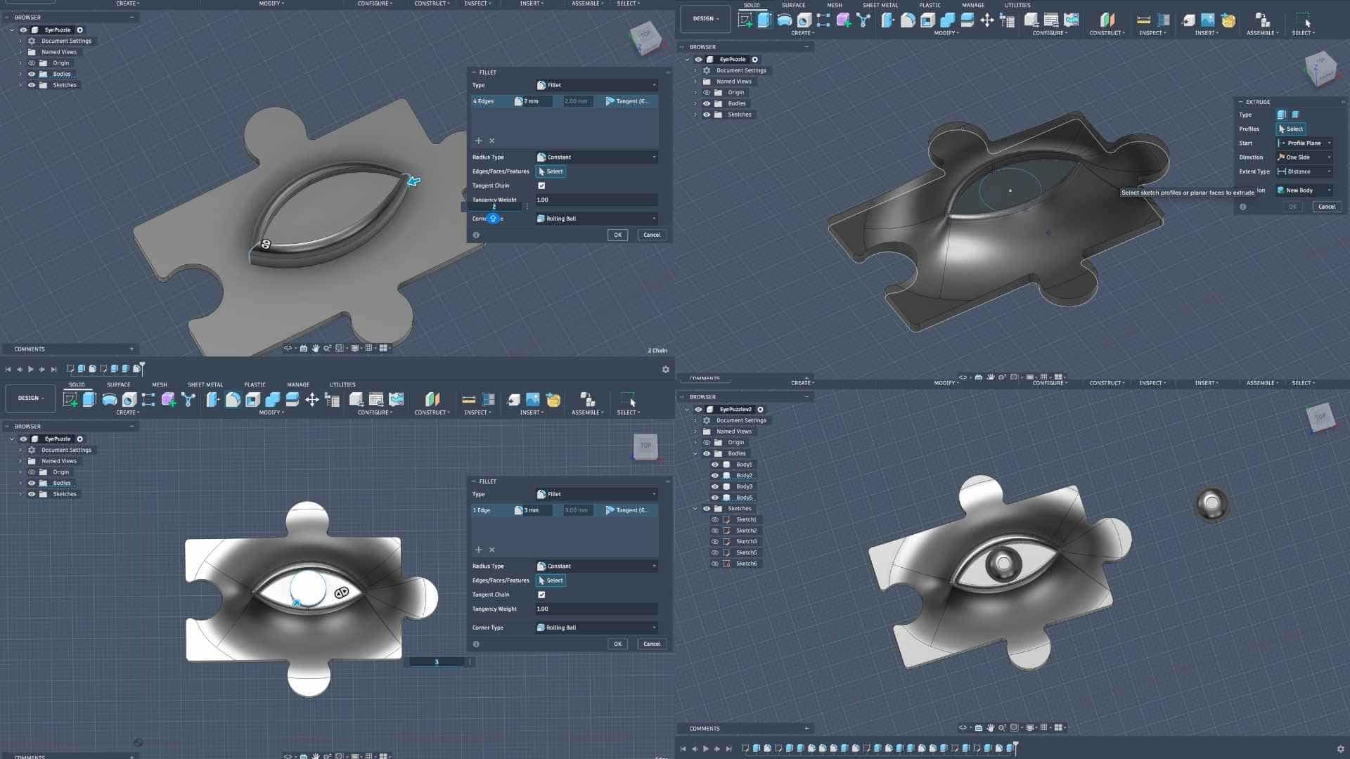
Eyeball Modeling and Tool Limitation
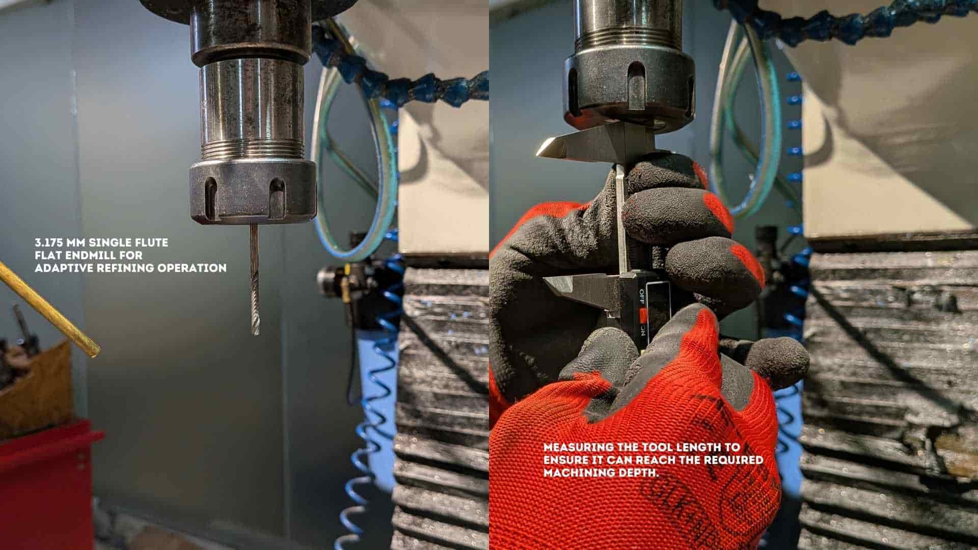
When I began modeling the eyeball detail, I encountered a critical constraint. The gap and feature size required for the eyeball were smaller than the diameter of the available 3.175 mm end mill. This meant the tool would not be able to access or accurately define those features during milling, leading to loss of detail or potential tool collision.
Hybrid Fabrication Decision
To address this limitation, a hybrid approach was adopted. Instead of forcing all details into the milling process, the eyeball was separated as an independent component to be 3D printed. This allowed for finer resolution and detail, which would not be achievable with the milling tool alone.
Eyeball Placement Strategy (Recess Creation)
To integrate the 3D printed eyeball into the mold workflow, I created a recessed pocket at the intended location. This pocket ensures that the eyeball can be placed accurately and consistently onto the wax model before pouring silicone, maintaining alignment within the final composition.
Mold Boundary and Body Preparation
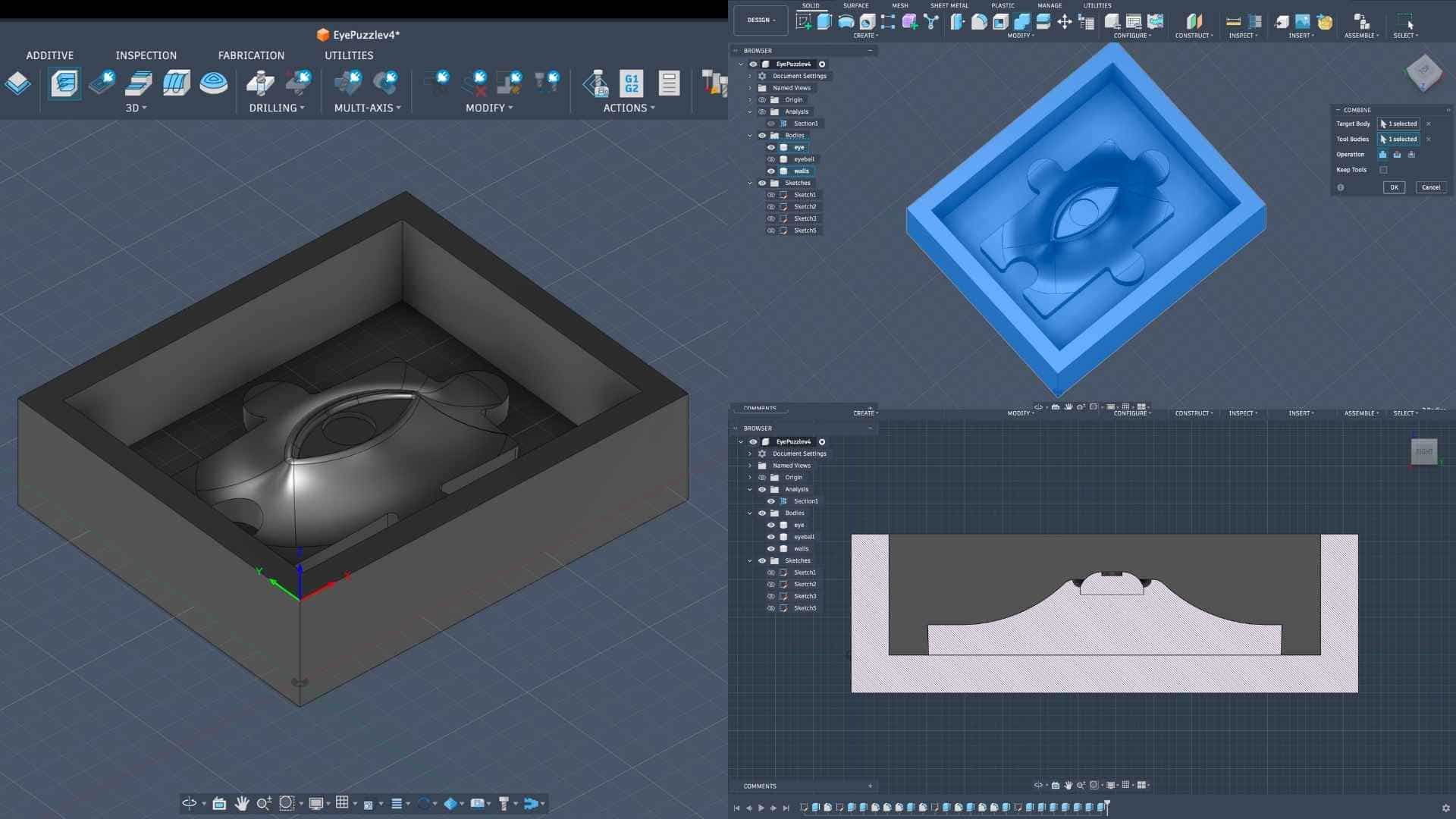
Once the internal features were resolved, I added outer walls around the geometry to define the mold boundary. The remaining elements were combined into a single body to prepare a clean positive master. These walls ensure that the silicone, when poured, forms a contained and structurally stable mold.
Section Analysis and Validation
A sectional view was used to inspect the model internally. This step helped verify depths, curvature continuity, and overall geometry. It also ensured that there were no problematic undercuts or inaccessible regions that could complicate molding or demolding.
Fabrication Logic (Positive - Negative Workflow)
The final workflow follows a standard casting sequence. The machinable wax is milled as the positive master. Silicone is then poured over this to create a negative mold. Finally, resin is cast into the silicone mold to produce the final positive object. Since resin is rigid, a flexible mold material like silicone is used to allow safe removal without damaging the cast.
CAM Setup - Operation 1: 3D Adaptive Clearing (Roughing)
I began the CAM workflow by importing the Fab Lab tool library into Fusion 360. This ensures that all machining operations use tools that are physically available, avoiding mismatches between digital setup and actual fabrication.
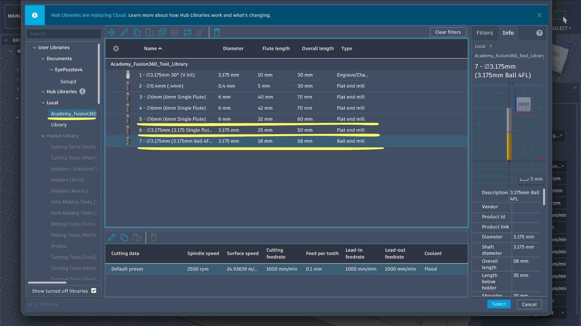
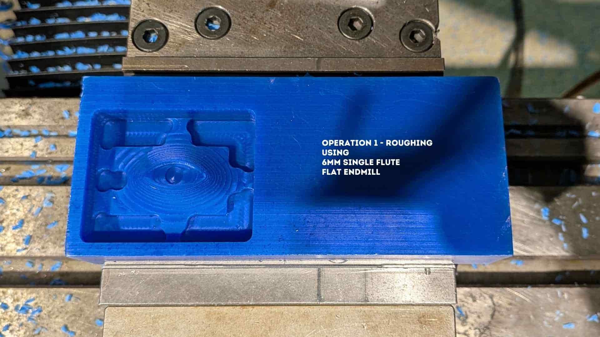
For the first operation, I selected a 6 mm single flute flat end mill. This tool is appropriate for roughing because of its larger diameter, which allows faster material removal and better chip evacuation, especially in softer materials like machinable wax.
Setup Definition (Work Coordinate + Stock)
Before defining the toolpath, I created a Setup to establish the machining context.
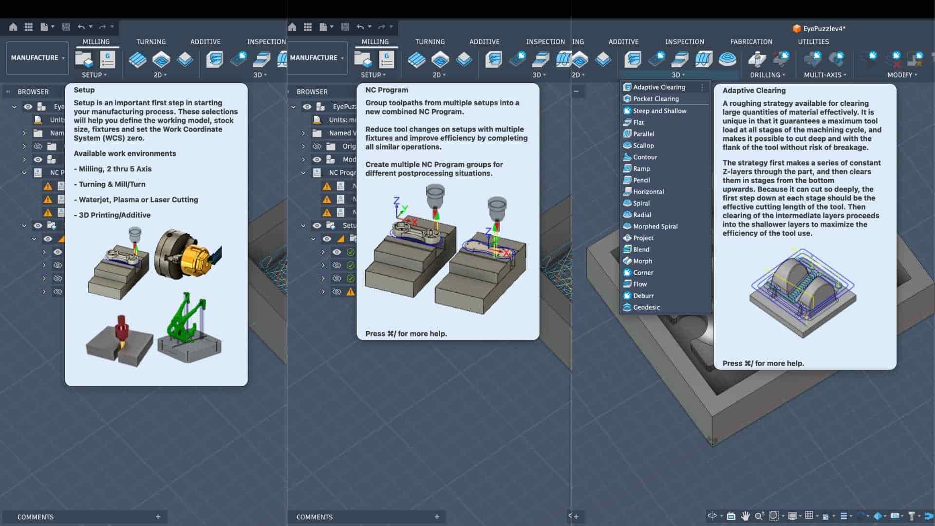
This step is critical because all tool movements reference this origin. Any misalignment here would result in incorrect machining.
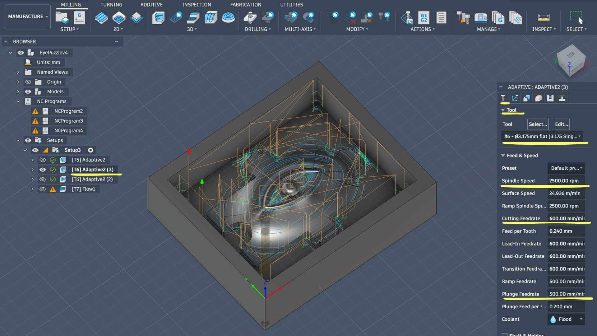
Tool Selection and Cutting Parameters
Within the Adaptive operation, I selected the 6 mm flat end mill from the imported library.
Key parameters defined:
These values are moderate and suitable for wax, balancing material removal rate with tool stability. Since it’s a single flute tool, feed per tooth remains relatively high, which helps prevent clogging.
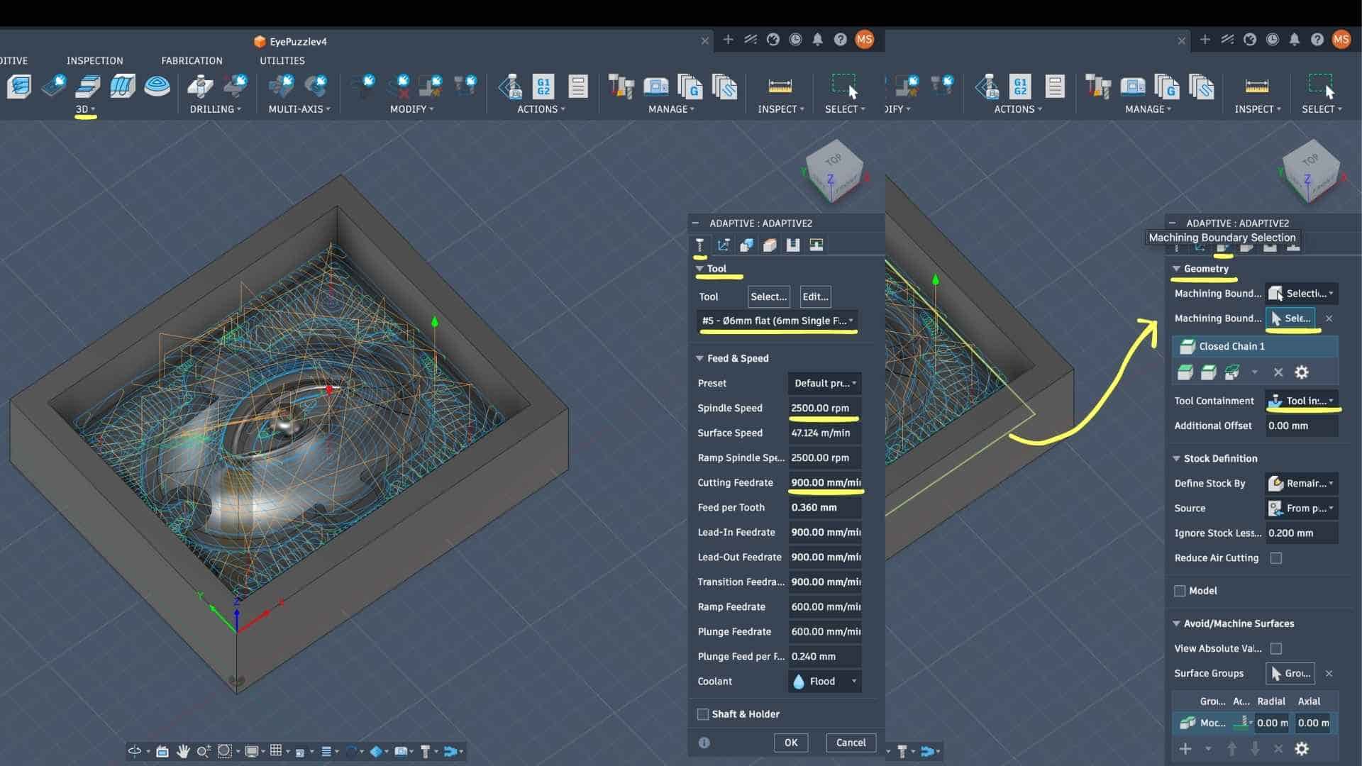
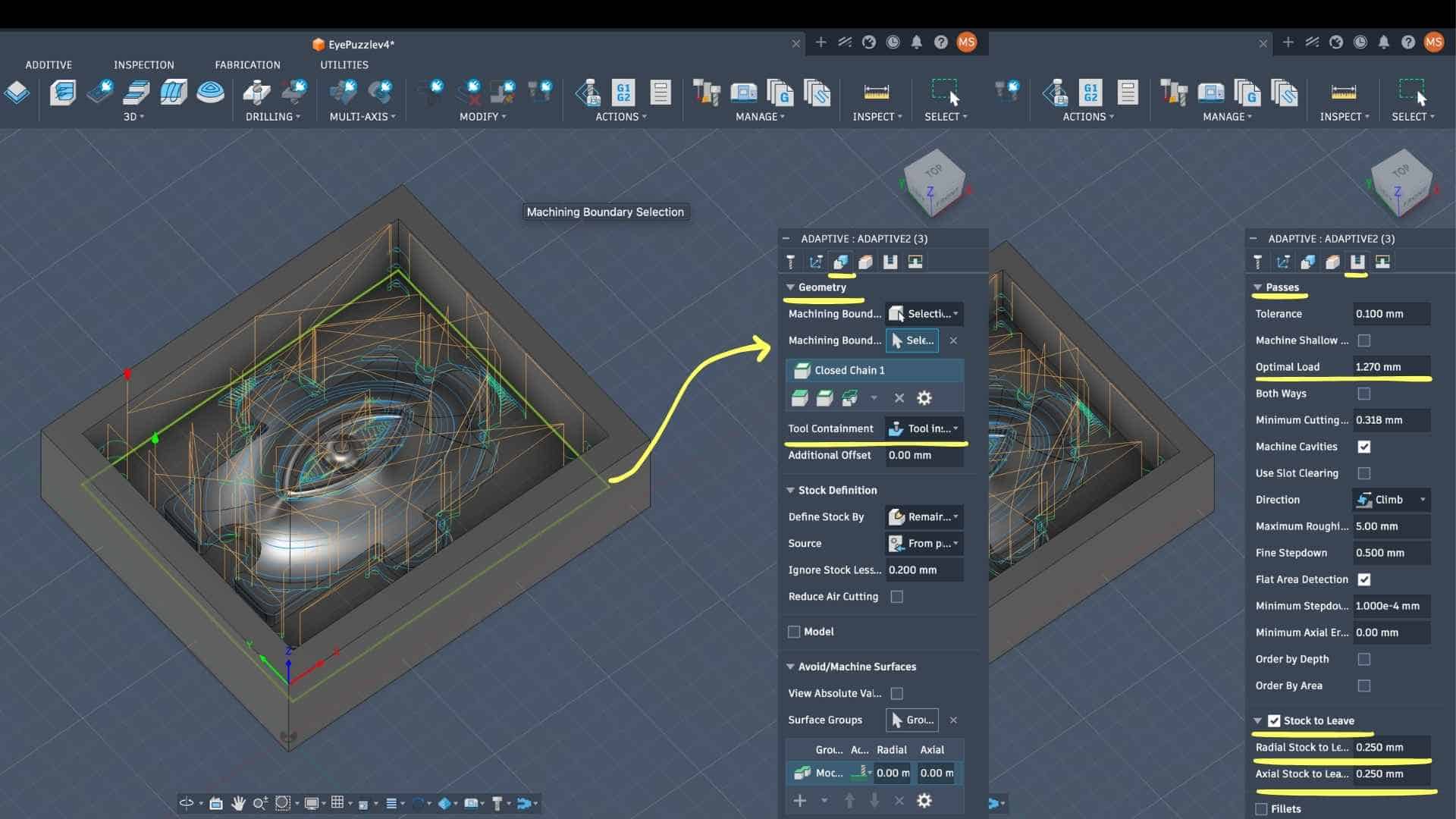
Geometry Definition (Machining Boundary)
The machining boundary was explicitly selected using a closed chain around the inner region.
This ensures that the tool does not travel beyond the intended region, preventing unnecessary air cutting or collisions with the mold walls.
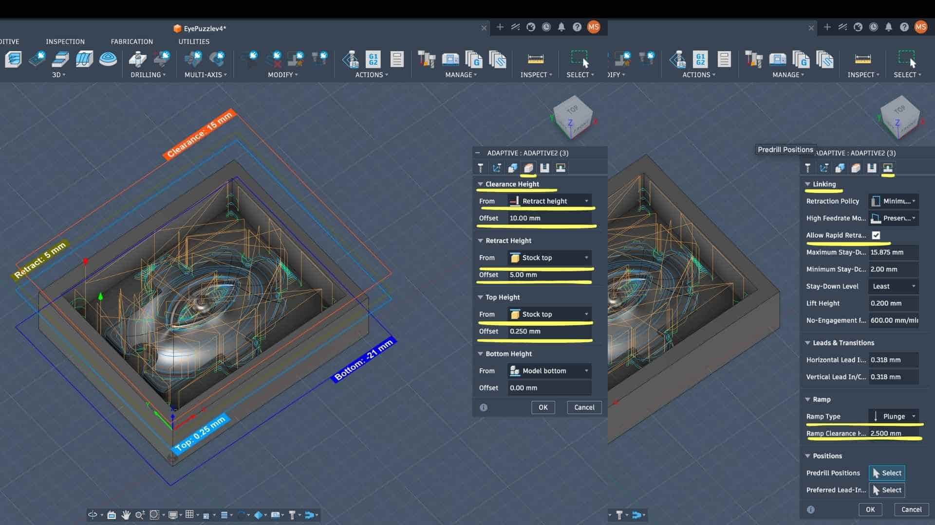
Height Settings (Z Control)
The vertical limits of machining were defined carefully:
The small top offset (0.25 mm) ensures that a thin layer of material is preserved, avoiding accidental overcut during roughing.
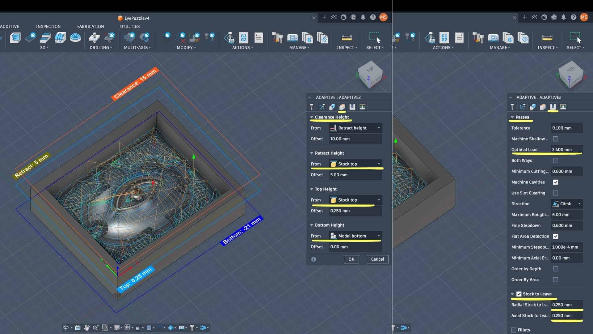
Passes (Material Removal Strategy)
This is where the adaptive clearing behavior is defined.
→ Controls the step-over; ensures consistent tool engagement and avoids tool overload
→ Determines how deep each pass cuts vertically
→ Allows smoother transitions near detailed regions
→ Provides better surface finish and tool stability
Stock to Leave:
Leaving stock is intentional. This operation is only for roughing; a finishing pass (likely with a ball end mill) will remove this remaining material to achieve better surface quality.
Linking and Tool Entry Strategy
The linking tab defines how the tool moves between cuts.
This reduces machining time while maintaining safe entry into material. Since wax is soft, plunge entry is acceptable here.
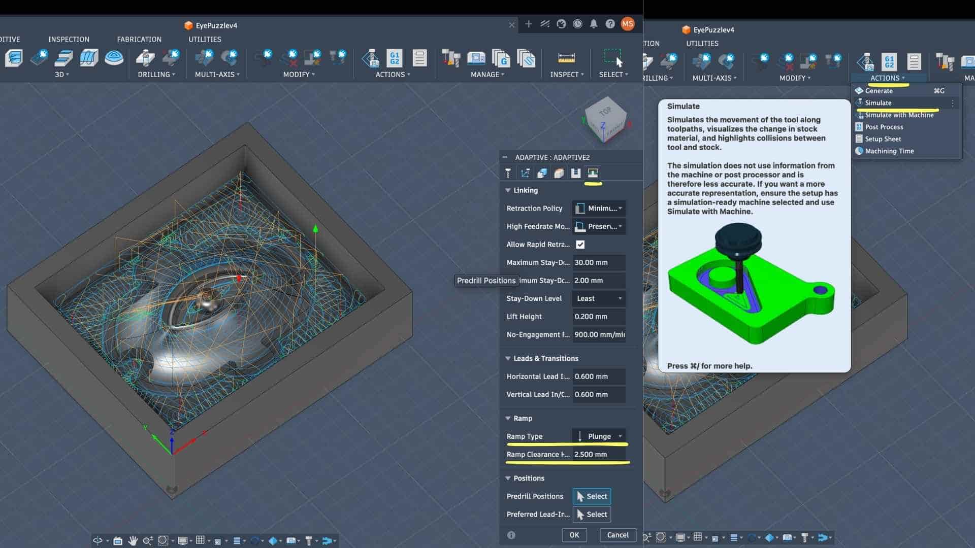
Simulation and Verification
After defining the toolpath, I ran a simulation to:
This step acts as a validation before actual machining.
CAM Setup - Operation 2 & 3: Adaptive Refinement (Ø3.175 mm Flat End Mill)
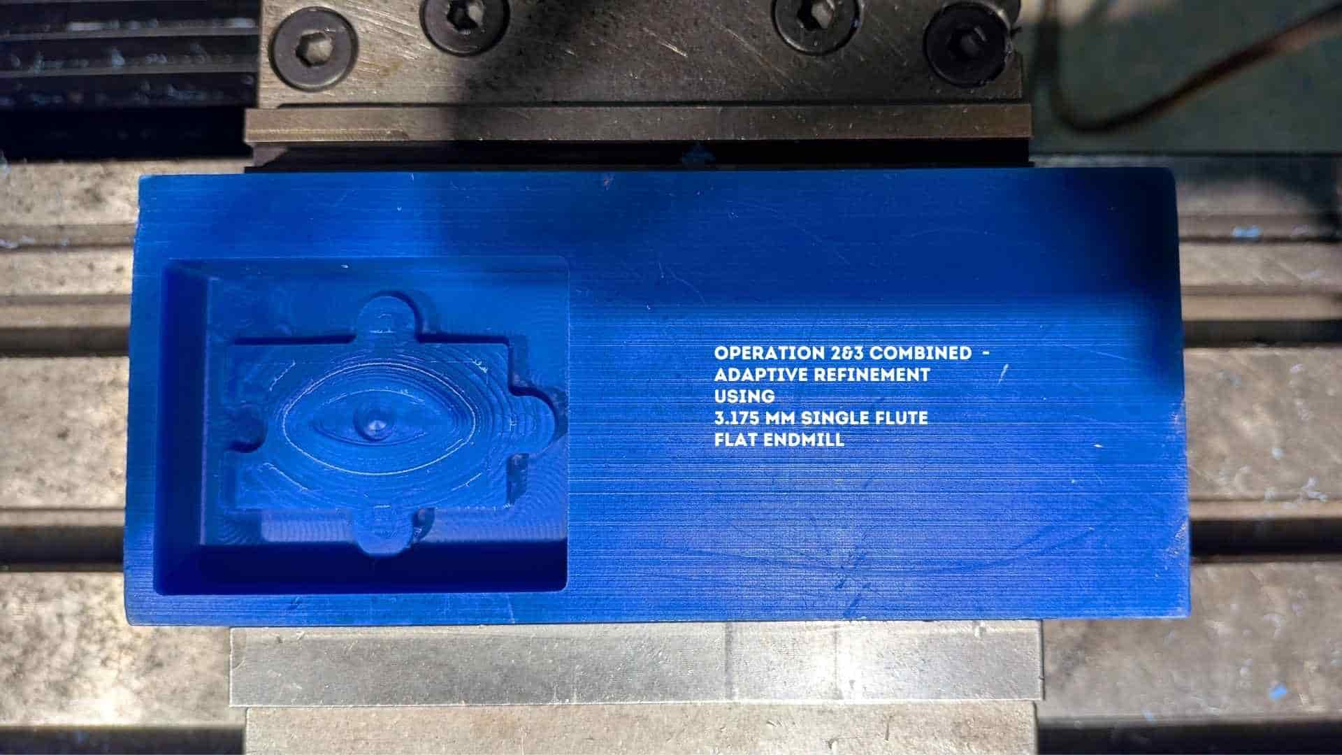
After the initial roughing pass using the 6 mm tool, I introduced a smaller Ø3.175 mm flat end mill to refine the geometry and access tighter regions that were not reachable earlier.
Instead of jumping directly to finishing, I performed two successive adaptive operations using the same tool. These passes progressively reduce the remaining stock and improve feature definition.
1. Tool Selection and Intent
The Ø3.175 mm flat end mill was chosen for its smaller diameter, allowing it to reach narrower regions and resolve finer geometry compared to the 6 mm tool.
Geometry and Boundary
The machining boundary remains consistent with the previous setup:
This ensures continuity between operations and avoids re-machining unnecessary areas.
Feed and Speed Adjustment
Compared to the 6 mm tool, parameters are scaled down:
The reduction in feedrate compensates for the smaller tool diameter, preventing excessive load and potential tool deflection.
Pass Strategy (Key Differences from Operation 1)
The most important changes happen here:
→ Reduced from previous operation to match smaller tool diameter
→ Maintains consistent tool engagement
→ Slightly reduced for better control in finer regions
→ Improves surface approximation before finishing
Stock to Leave:
Stock is still intentionally preserved for the final finishing pass.
Height and Linking Strategy
These remain largely consistent:
Because the material is wax, aggressive entry strategies are acceptable, and consistency across operations avoids unexpected tool motion.
Why Two Passes with the Same Tool?
Running the same tool twice is not redundant, it improves machining quality:
This staged reduction:
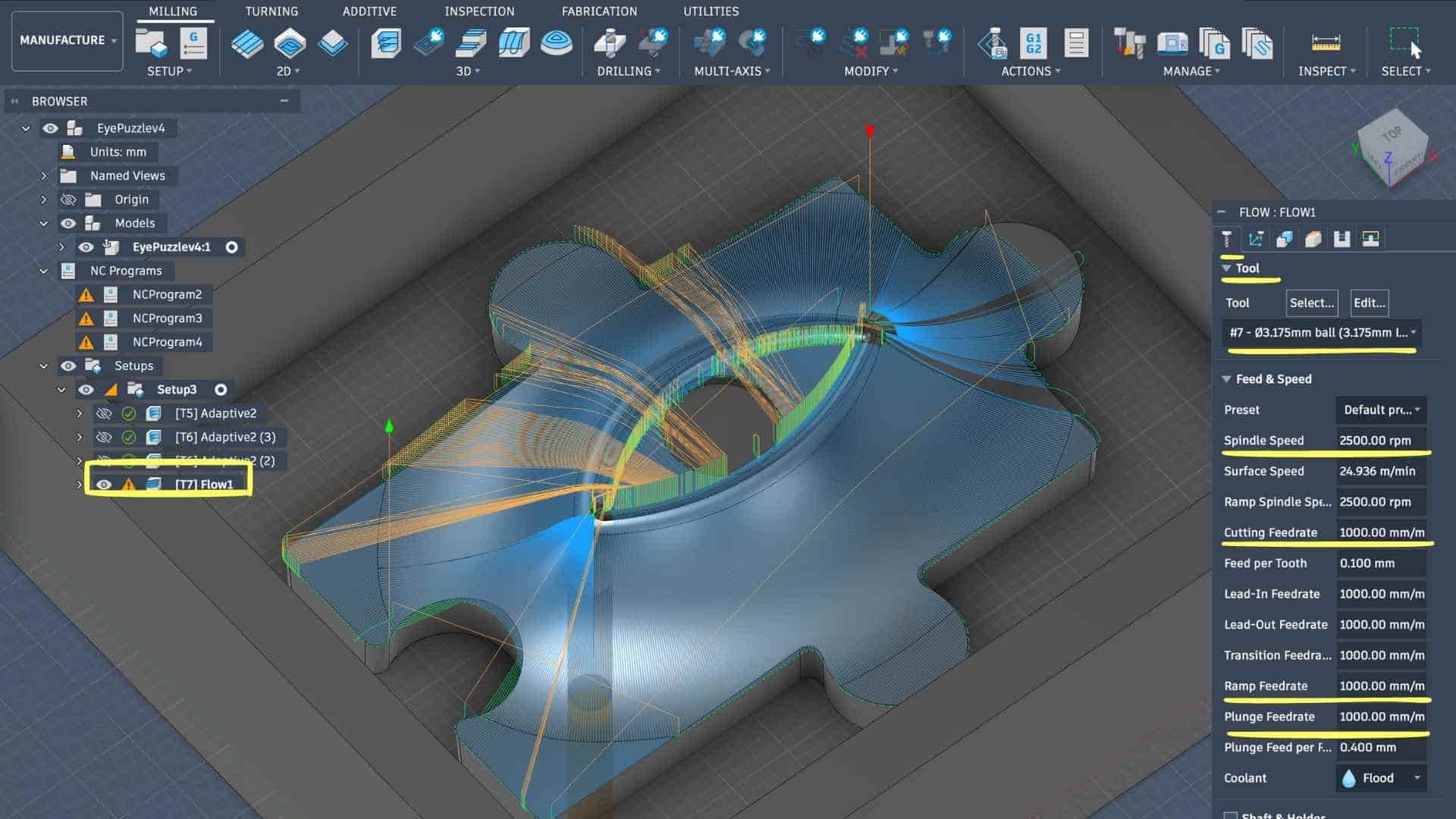
CAM Setup - Operation 4: 3D Finishing (Flow) - Ø3.175 mm Ball End Mill
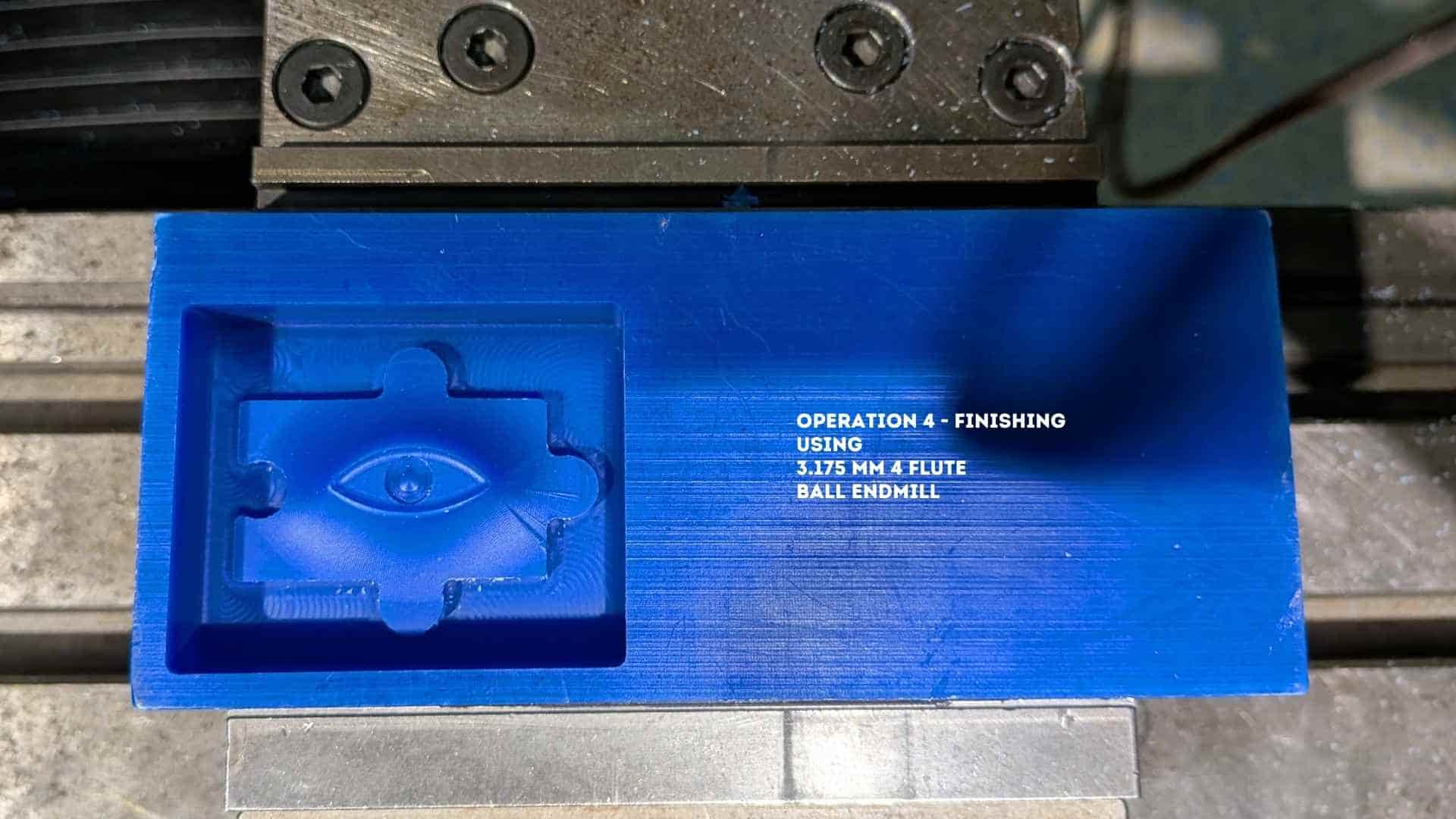
After completing the roughing and refinement passes with flat end mills, I switched to a Ø3.175 mm ball end mill for the final finishing operation. Unlike flat tools, the ball end mill enables smooth machining of curved surfaces due to its point contact, making it suitable for organic geometries like the eye form.
For this operation, I used the Flow strategy, which follows the natural curvature of selected surfaces, producing a continuous and uniform surface finish.
Tool Selection and Cutting Parameters
The Ø3.175 mm ball end mill was selected from the tool library.
Compared to previous operations, the feedrate is increased slightly because finishing involves lighter cuts and lower material engagement. The tool is not removing bulk material, so higher feedrates are acceptable without compromising stability.
Geometry Selection (Drive Surfaces)
Instead of defining a boundary like in adaptive clearing, the Flow strategy requires explicit surface selection:
This is a key step:
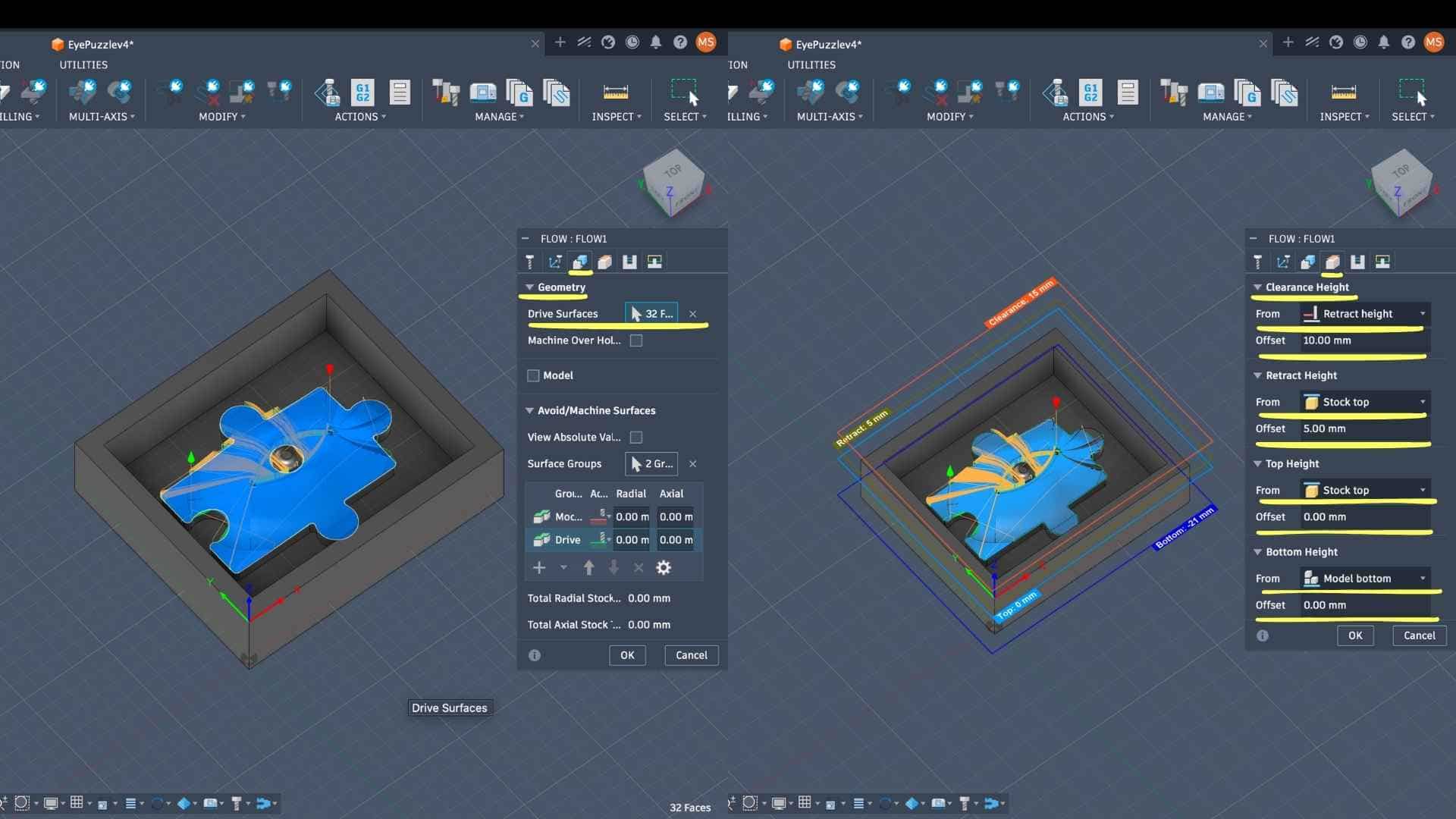
Height Settings (Z Control)
Unlike roughing, no top offset is maintained here because this is the final pass—all remaining stock is intended to be removed.
Pass Strategy (Surface Quality Control)
This is the most critical section for finishing:
→ Controls toolpath accuracy relative to the model
→ Defines the spacing between adjacent passes
→ Directly affects surface finish (smaller = smoother surface)
→ Represents the residual scallop height between passes
→ Lower value ensures minimal visible tool marks
→ Improves efficiency while maintaining consistency
→ Reduces unnecessary toolpath noise and creates fluid motion
→ This is a finishing pass, so no material is intentionally left
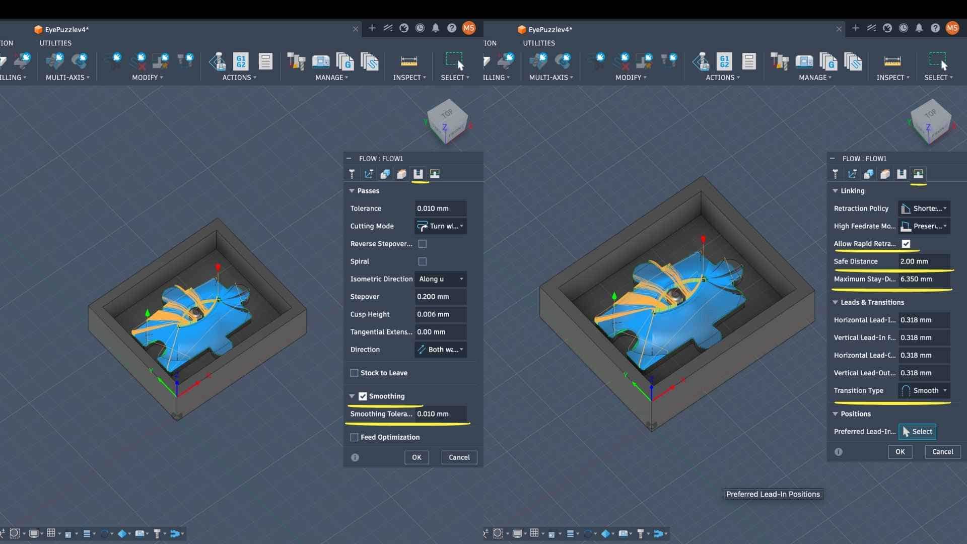
Linking and Motion Control
→ Keeps the tool engaged longer, reducing retract movements
→ Avoids abrupt direction changes, improving surface quality
→ Ensures gradual tool entry and exit
These parameters collectively reduce tool marks and improve continuity across the surface.
Why Flow Strategy?
The Flow toolpath is particularly effective here because:
This is important for molds, where surface imperfections directly transfer to the final cast.
Simulation and Verification
A final simulation was performed to:
This confirms readiness before actual machining.
Exporting G Codes
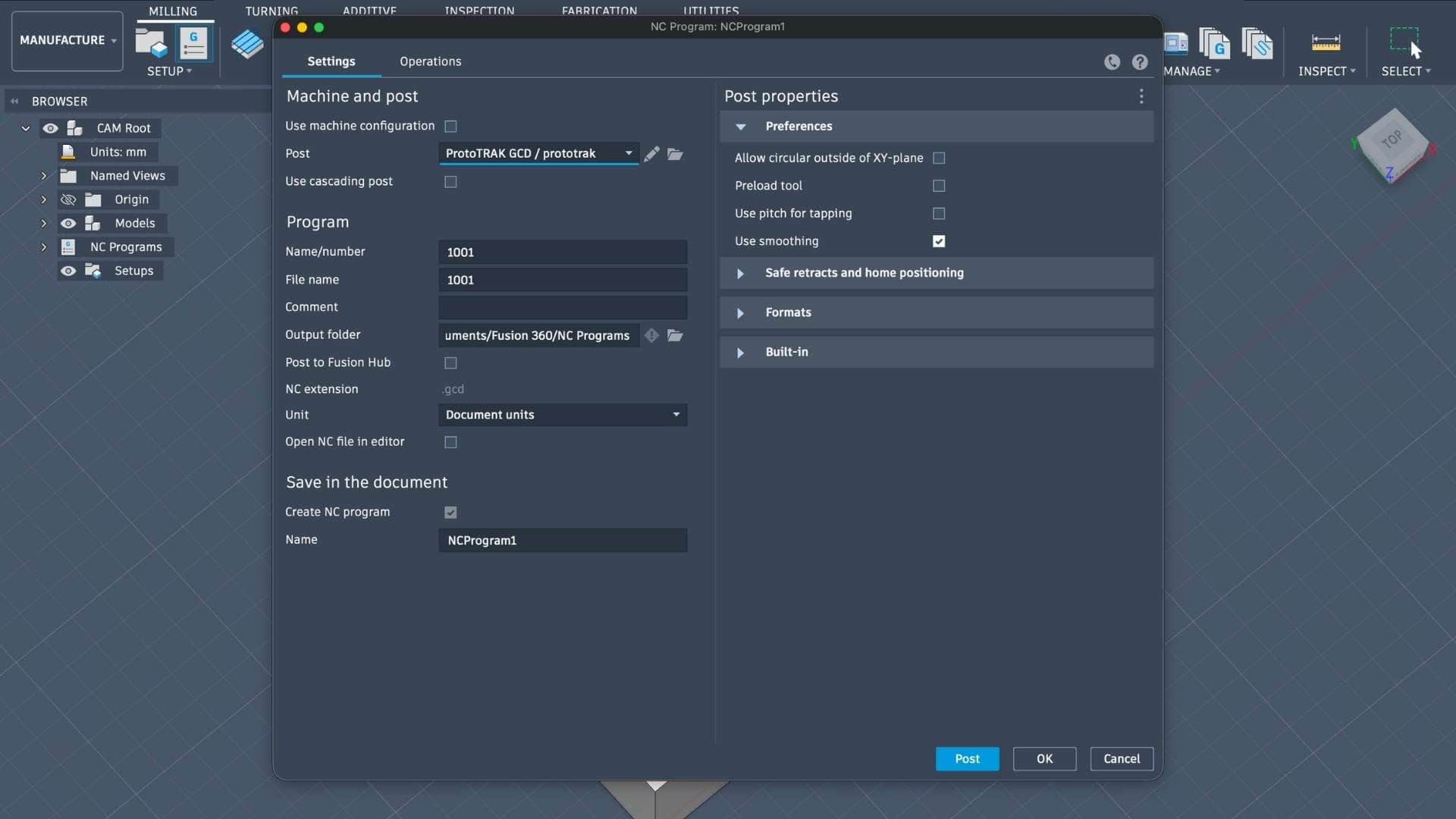
Milling Setup - Machine Overview (ProtoTRAK DPM RX2)
Find the datasheet here.
The milling operations were carried out on a ProtoTRAK DPM RX2, a 3-axis CNC milling machine commonly used for precision subtractive manufacturing.
This machine combines manual mill ergonomics with CNC control, making it suitable for controlled machining of softer materials such as machinable wax.
Machine Characteristics (Context for Process)
For this project, the machine was operated in CNC mode using generated toolpaths (G-code) from Fusion 360.
Relevance to This Workflow
The choice of this machine aligns with the requirements of the process:
Supports multiple tool changes, which is necessary for:
Operating the Milling Machine (ProtoTRAK DPM RX2)
1. Pre-Operation Checks
Before starting the machine, basic system conditions were verified to ensure safe and stable operation.
- Checked lubricant level, coolant level, and air pressure supply
- Ensured the machine and workspace were clean and free of obstructions
2. Machine Overview & Startup
The ProtoTRAK DPM RX2 milling machine was powered on and initialized to enable controlled movement.
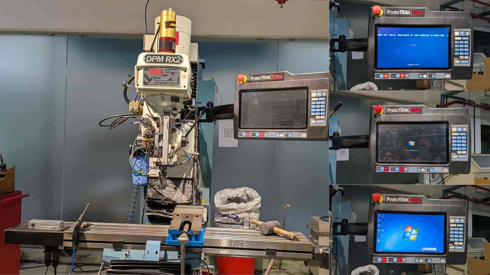
- Turned on the main power switches
- Waited for the system interface to load completely
- Pressed RESET until the indicator light turned on
- This activates the servo motors
3. Workpiece Setup (Fixturing)
The machinable wax block was securely fixed in the vice to prevent any movement during machining.
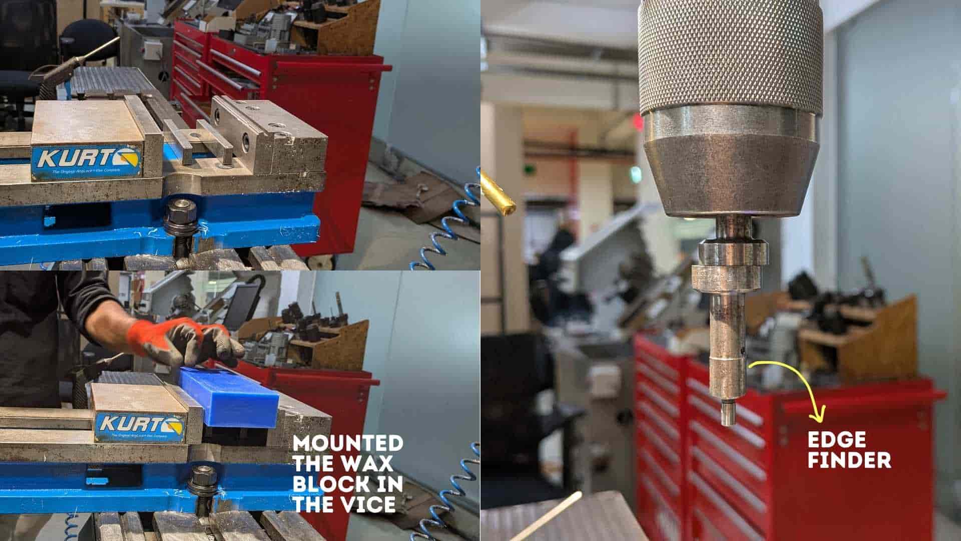
- Mounted the wax block in the vice
- Ensured proper alignment with machine axes
- Tightened the setup firmly for stability
4. Tool Setup - Edge Finder (X and Y Origin)
An edge finder was used to establish the X and Y origin of the workpiece.
- Installed the edge finder tool
- Located the edges of the workpiece
- Set X and Y zero positions based on these edges
- This aligns the physical setup with the CAM-defined origin
5. Z Reference Initialization
A safe Z reference was established to avoid unintended collisions and maintain consistency.
- Accessed: SYSTEM → SETUP → REFERENCE POSITION
- Selected: Z RETRACT → SET → ABSOLUTE SET
- This defines a consistent machine-level Z reference
6. DRO (Digital Readout) Setup
The DRO was used to define the working coordinate system.
- Set X and Y values and applied ABSOLUTE SET
- For Z, used a fixed base reference instead of the top surface
- This ensures consistency even after material is removed during machining
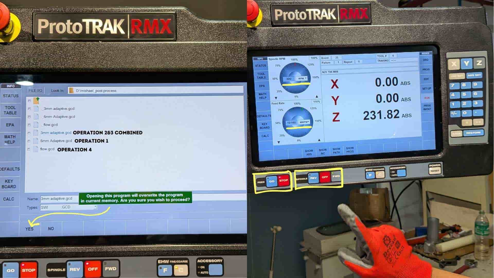
7. Program Loading
The toolpath generated in CAM was loaded into the machine.
- Used PROGRAM IN/OUT to load the G-code
- Selected the required operation (starting with the 6 mm tool)
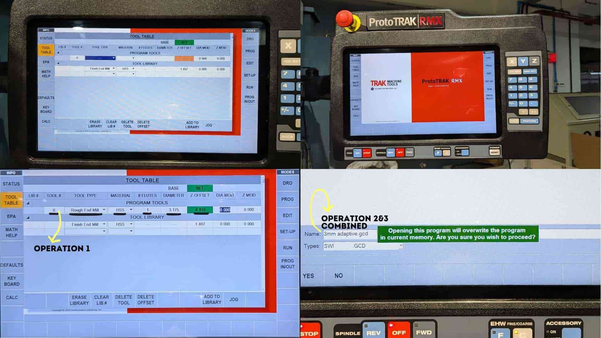
8. Tool Table Configuration
Tool parameters were defined so the machine could correctly interpret the tool geometry and offsets.
- Opened the TOOL TABLE
- Entered tool diameter, tool type, and Z reference (BASE)
- Applied ABSOLUTE SET to confirm values
9. Manual Positioning and Reference Check
The tool was manually positioned to verify alignment with the defined references.
- Moved the tool to the base reference point
- Confirmed alignment with the CAM setup
10. Toolpath Verification (TRAK Mode)
A manual verification step was performed before full execution to prevent errors.
- Entered TRAKing mode
- Manually guided the tool to confirm origin
- Used FORWARD to step through the toolpath
- If correct, stopped and switched to CNC RUN mode
11. Program Execution
Once verified, the machining operation was executed automatically.
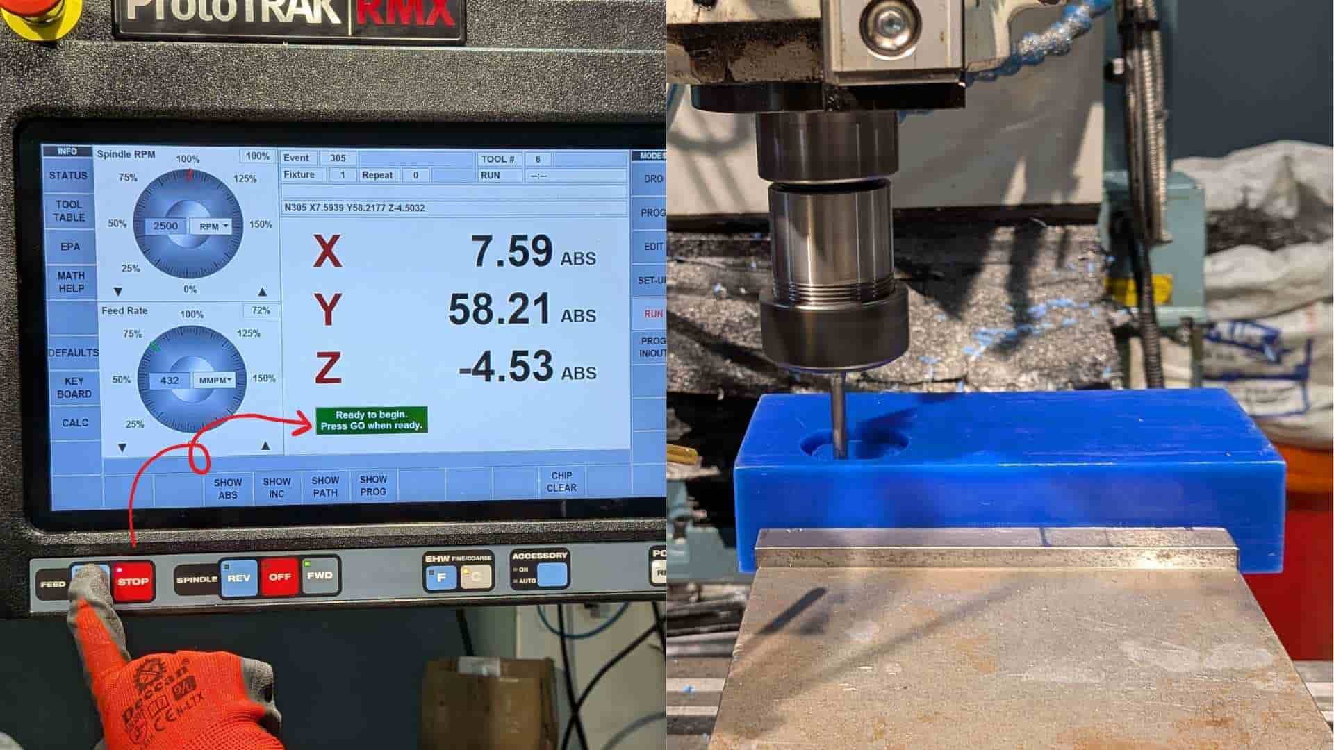
- Pressed GO to start the program
- The machine followed the predefined toolpath
12. Tool Change and Subsequent Operations
The same workflow was repeated for each machining operation and tool.

- Changed the tool as required (flat end mill, ball end mill, etc.)
- Repeated DRO setup and Z referencing for each tool
- Updated TOOL TABLE parameters accordingly
- Ensured alignment and accuracy were maintained across all operations
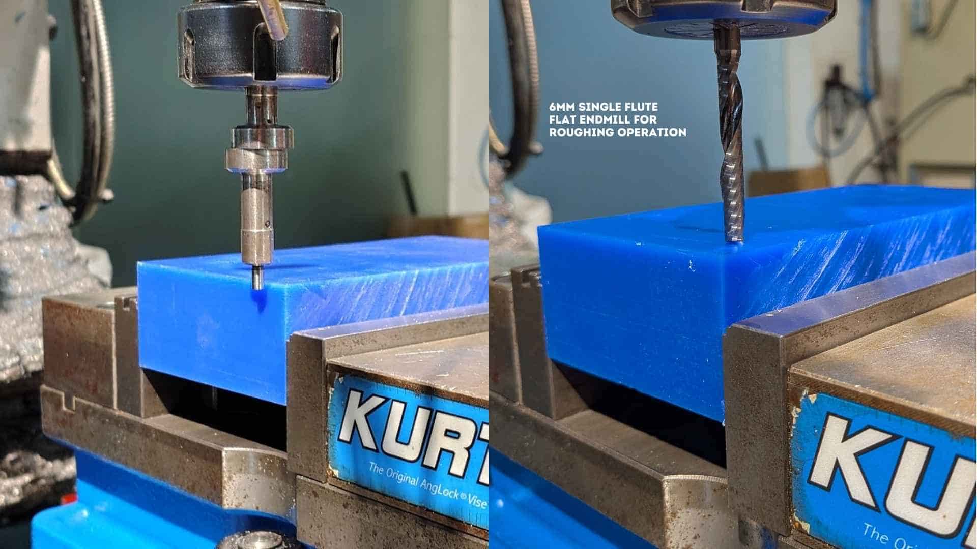
13. Operation 1 - Roughing
The first operation used a 6 mm single flute flat end mill to remove bulk material and establish the primary cavity shape.
14. Operation 2 & 3 - Adaptive Refinement
Two adaptive passes using a 3.175 mm flat end mill refined the geometry, improving detail and preparing the surface for finishing.
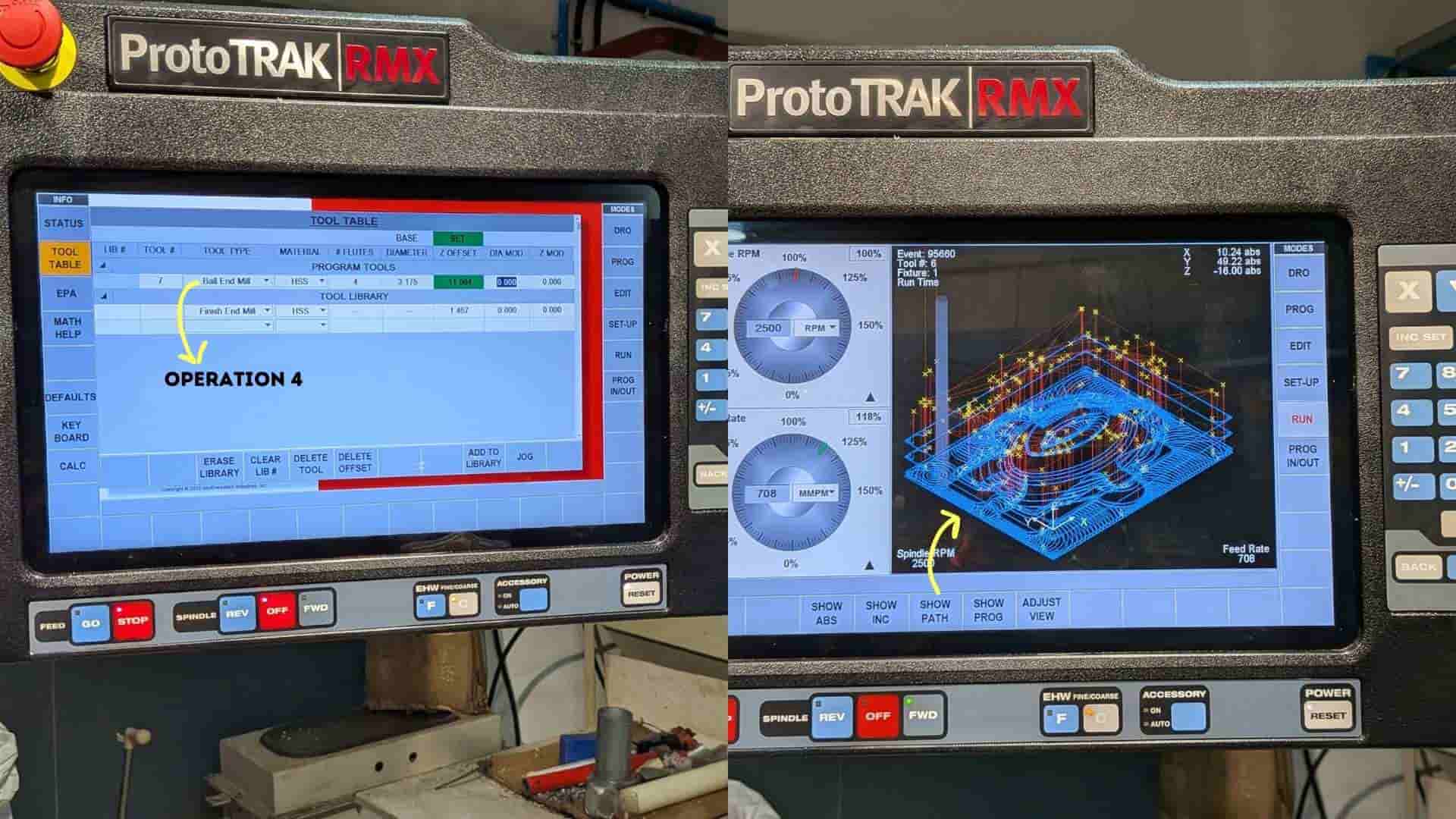
15. Operation 4 - Finishing
A 3.175 mm ball end mill was used for finishing, enabling smooth surface transitions and accurate reproduction of curved geometry.
Resin Printing - Eyeball Component
1. Model Preparation and Import
The 3D model of the eyeball component was imported into the slicing software and prepared for resin printing. The model was positioned at the center of the build platform, and its orientation was adjusted to reduce suction forces and improve surface quality. The geometry was checked for errors before proceeding.
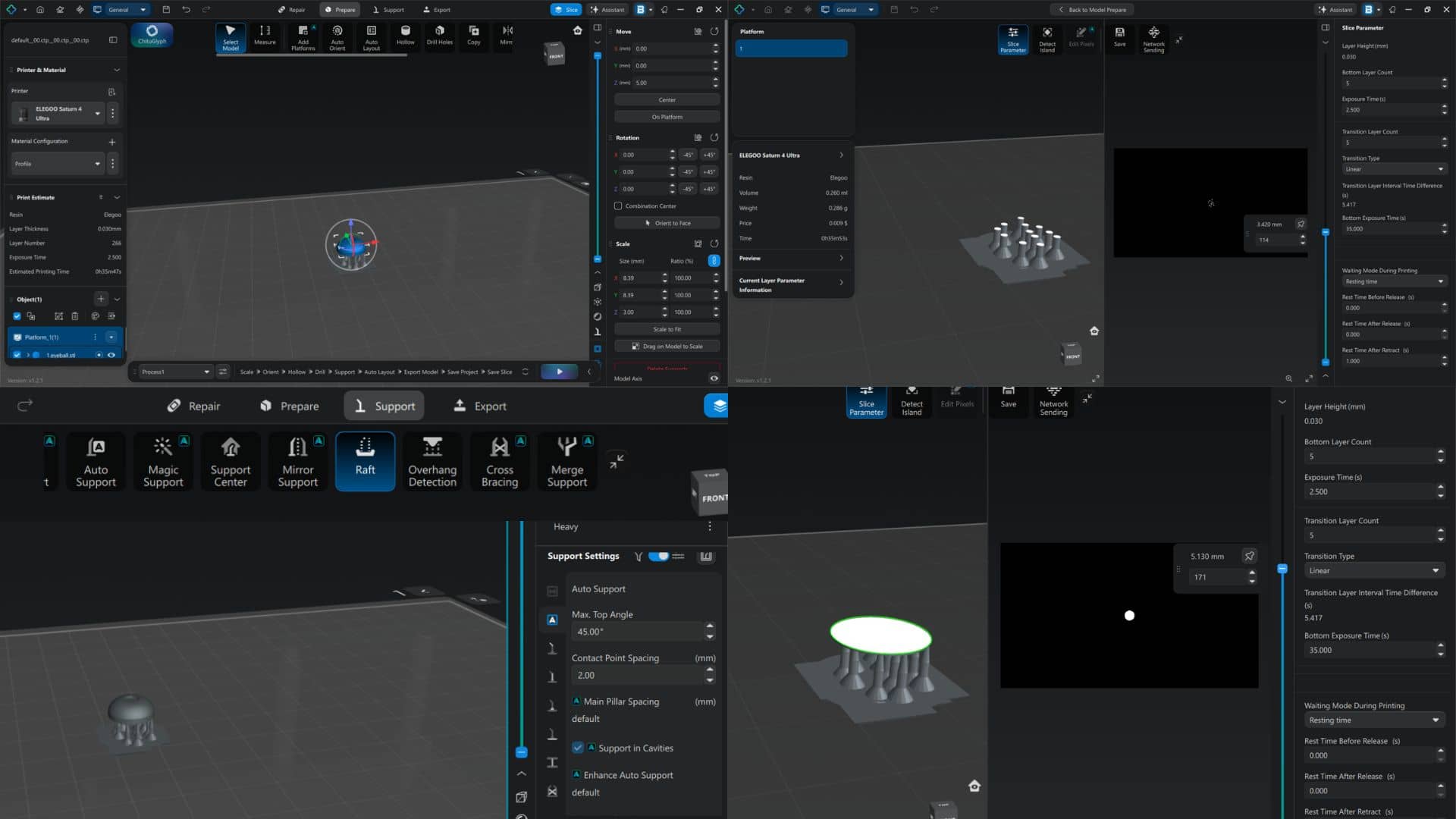
2. Support Generation
Supports were generated to stabilize the model during the printing process. Auto-support was applied using default parameters, and support density and contact points were adjusted for small geometry. A raft/base was added to ensure proper adhesion to the build plate. Overhangs were carefully supported to avoid deformation during printing.
3. Slicing and Parameter Setup
The model was sliced using appropriate resin printing parameters. Layer height was set to 0.03 mm, exposure time to approximately 2.5 seconds, and bottom exposure time to around 35 seconds. Transition layers were enabled to ensure gradual curing between layers. Print time and material usage were estimated before starting the print.
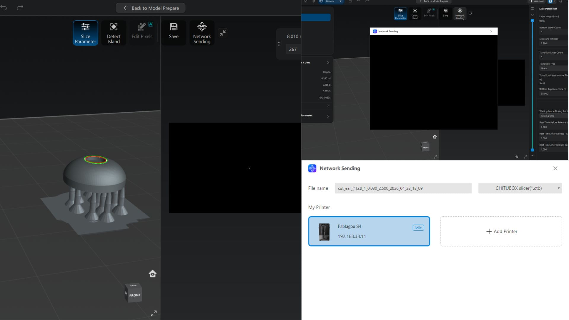
4. File Transfer and Printer Setup
The sliced file was exported in .ctb format and transferred to the resin printer via network connection. The printer status was checked to ensure it was ready before starting the print.
5. Printing Process
The print was initiated using the printer interface. Initial layers were observed to ensure proper adhesion to the build plate. The build platform lifted gradually as each layer was cured during the process.
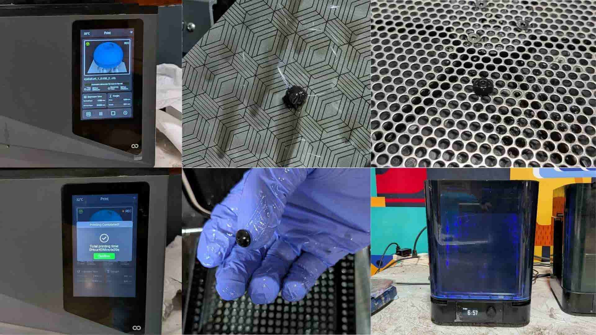
6. Post-Processing (Washing and Cleaning)
After printing, the part was removed from the build plate and washed in a cleaning solution to remove uncured resin. Excess resin was cleaned from the surface and cavities. Supports were carefully removed to avoid damaging the part.
7. Curing
The cleaned part was placed in a UV curing chamber to achieve full material strength. The part was cured for the required duration based on the resin specifications. This step ensured proper hardness and dimensional stability.
8. Final Output
The final eyeball component exhibited smooth curvature and fine surface detail. The high resolution of resin printing allowed accurate reproduction of small features. Minimal post-processing was required, making it suitable for mold-making and casting.
Notes / Observations
- Proper support placement was critical for maintaining geometry.
- Model orientation significantly affected surface finish and print success.
- Thorough cleaning before curing helped avoid surface defects.
Silicone Mold Making and Resin Casting
1. Material Preparation
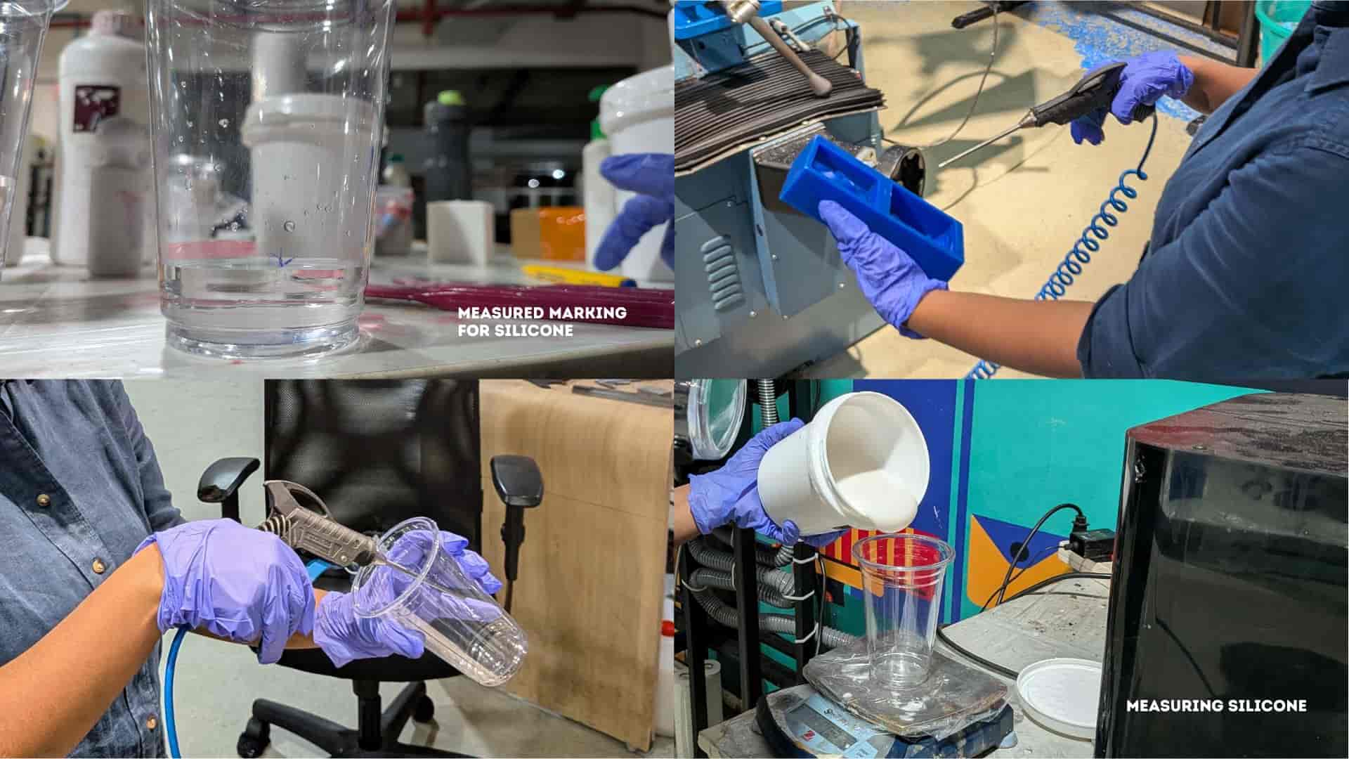
All required materials and tools were arranged before starting the process, including silicone (Part A), hardener (Part B), mixing containers, weighing scale, release spray, vacuum chamber, and the resin printed eyeball insert.
Aditya Silicone Rubber RTV - 1010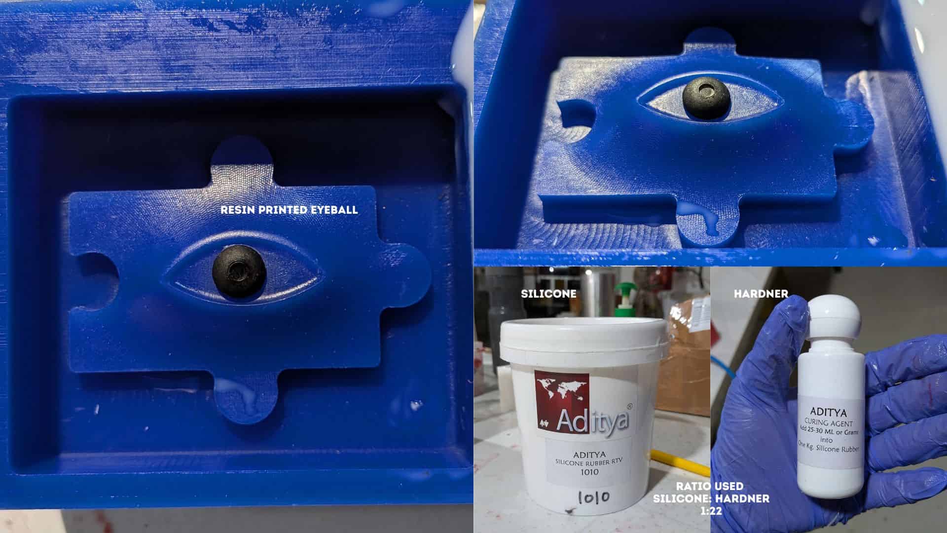
2. Measuring Silicone and Hardener
A clean container was placed on a weighing scale. Silicone was measured first, followed by the addition of hardener according to the required ratio. Care was taken to ensure accuracy for proper curing.
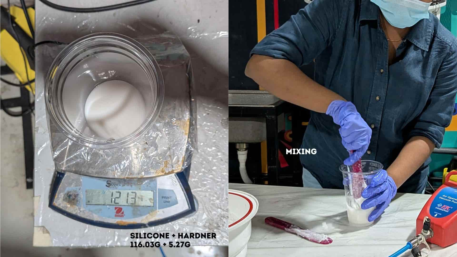
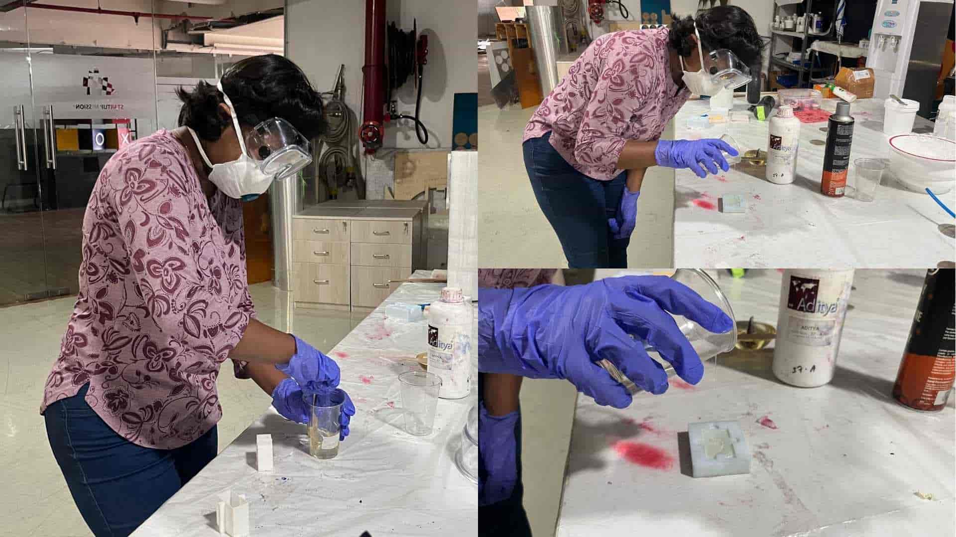
3. Mixing
The silicone and hardener were mixed thoroughly using a stirrer. The mixture was stirred slowly to achieve uniform consistency while minimizing air entrapment.
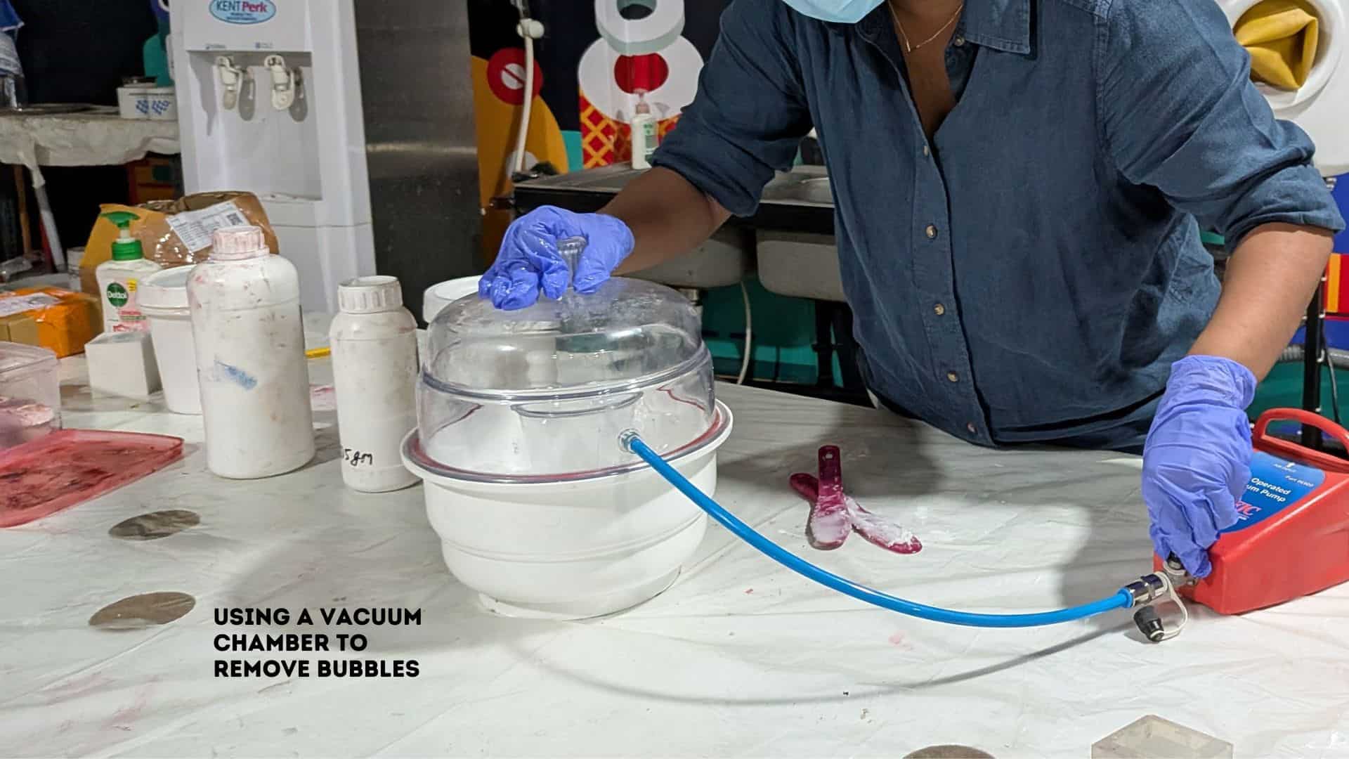
4. Degassing (Vacuum Chamber)
The mixed silicone was placed inside a vacuum chamber to remove trapped air bubbles. The material expanded and collapsed as the air was extracted, improving the final mold quality.
5. Mold Preparation
A release agent was applied evenly inside the mold cavity to prevent sticking. The mold surface was checked to ensure it was clean and ready for pouring.
6. Placement of Resin Printed Eyeball
The resin printed eyeball was placed into the mold cavity at the intended position. Proper alignment was ensured to maintain accuracy in the final cast.
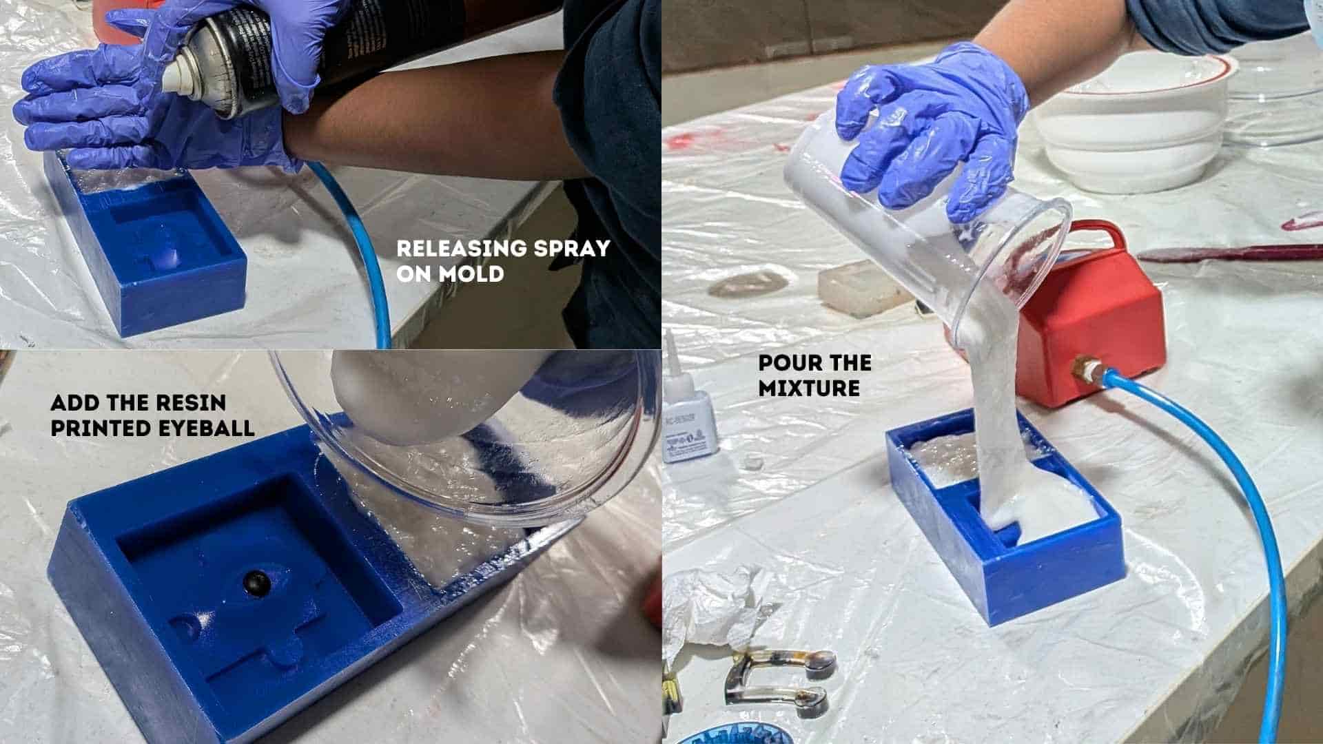
7. Pouring the Silicone
The silicone mixture was poured slowly into the mold from one side, allowing it to flow naturally and fill all cavities while minimizing bubble formation.
8. Curing
The filled mold was left undisturbed at room temperature to cure completely. Movement during this stage was avoided to maintain surface quality.
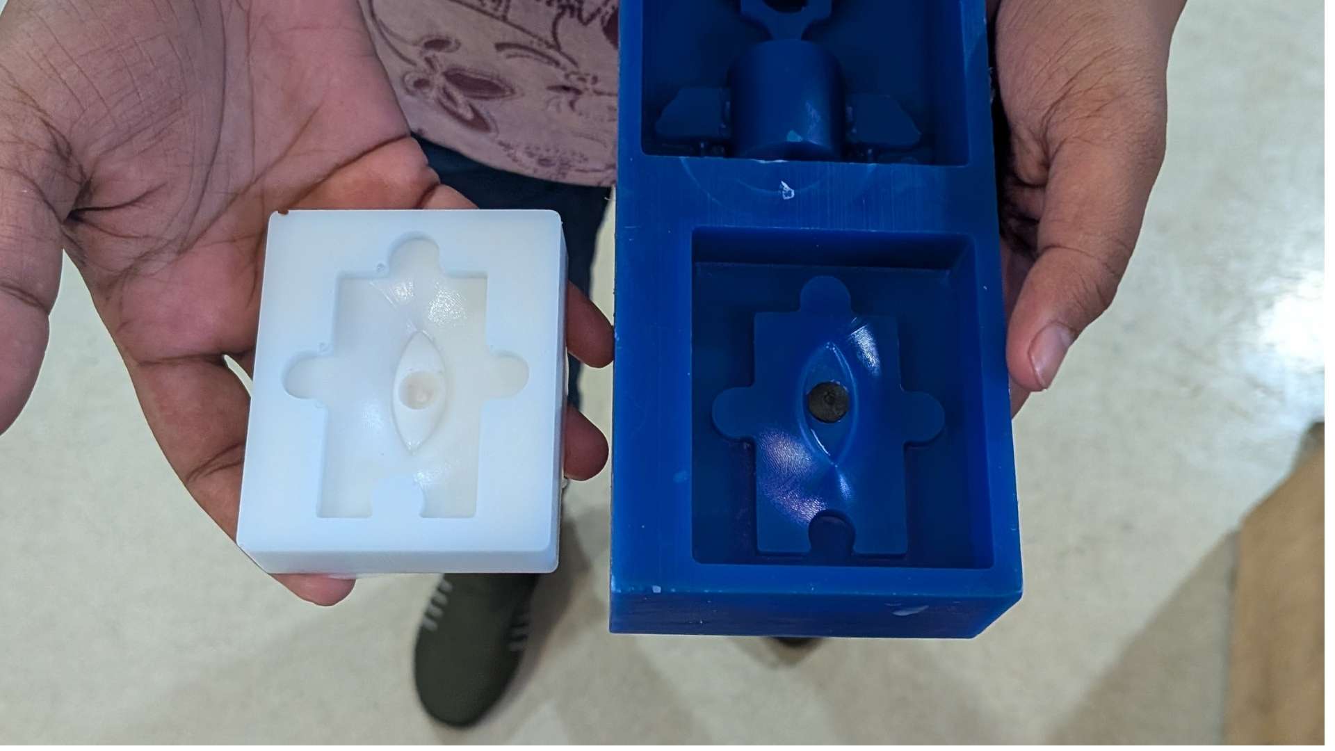
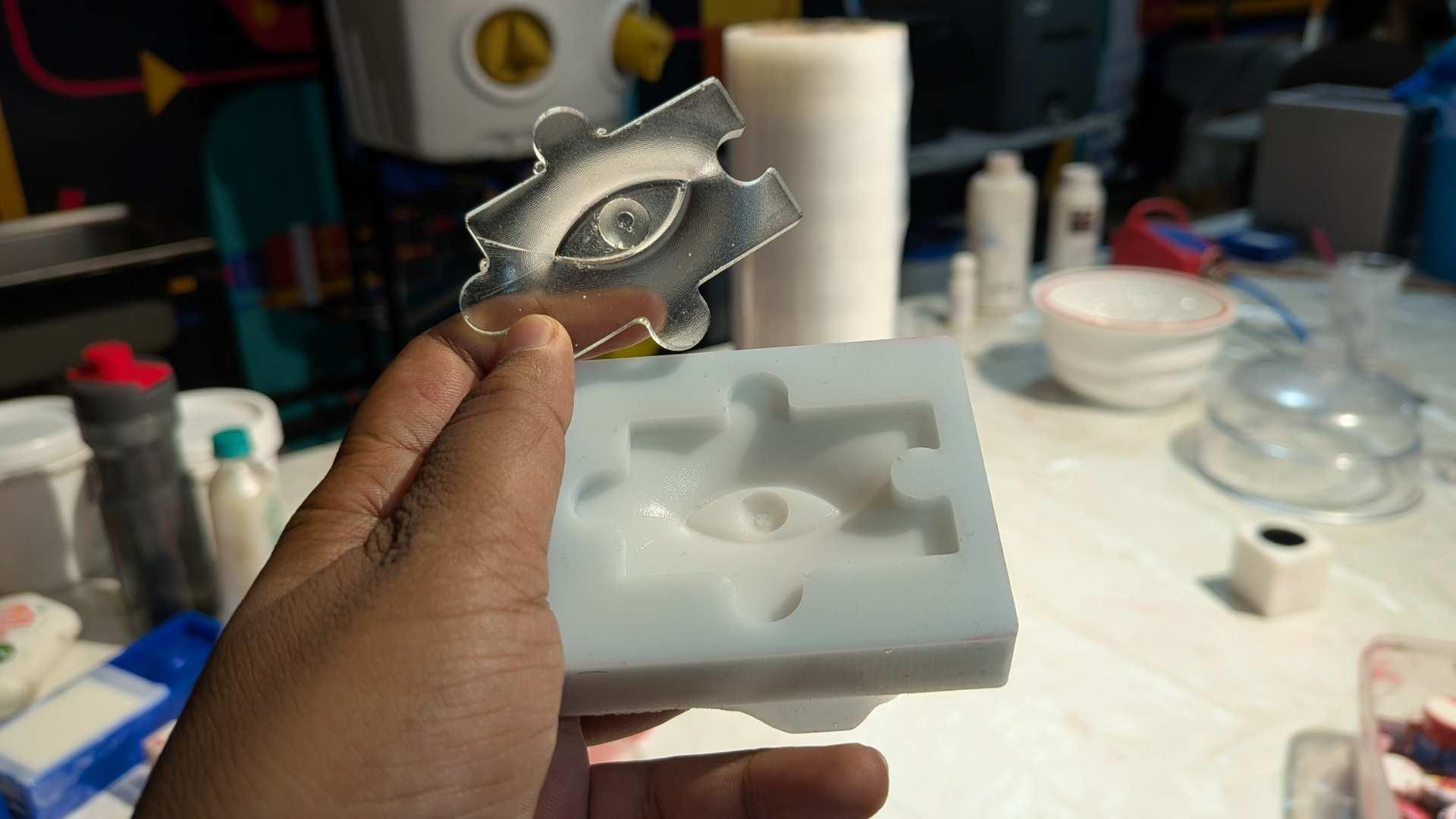
9. Demolding
After curing, the silicone mold was carefully removed. The internal geometry and details were inspected. Minor air bubbles were observed in some areas.
Resin Casting Process
1. Mold Preparation
The cured silicone mold was prepared for casting. The mold cavity was inspected to ensure it was clean, free of debris, and properly formed. A release agent can be applied if required, although silicone molds generally allow easy demolding.

2. Resin Preparation
Aditya Ultra Clear Cast Epoxy – 37The resin components (Part A and Part B) were prepared according to the required mixing ratio. A clean container was used, and the components were measured carefully to ensure proper curing.
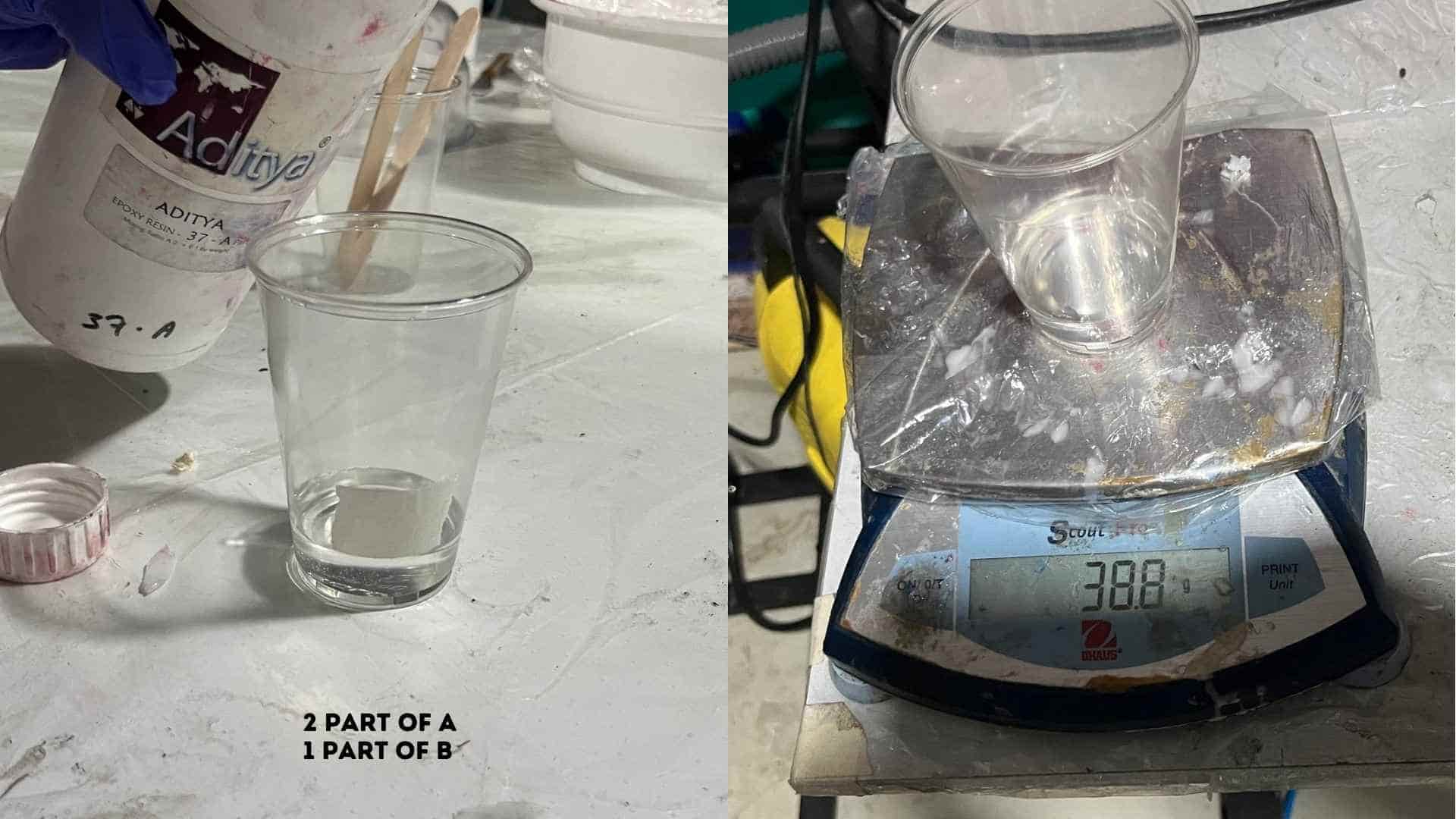
3. Mixing the Resin
The two resin components were mixed thoroughly. Stirring was done slowly and consistently to achieve a uniform mixture while minimizing air bubble formation.
4. Pouring into the Mold
The mixed resin was poured slowly into the silicone mold cavity. The pouring was controlled and done from one side to allow the resin to flow naturally and reduce air entrapment.
6. Curing
The filled mold was left undisturbed to cure at room temperature. Adequate curing time was ensured to allow the resin to fully harden and achieve structural stability.
7. Demolding
Once cured, the cast was carefully removed from the silicone mold. The flexibility of the silicone allowed easy removal without damaging the part.
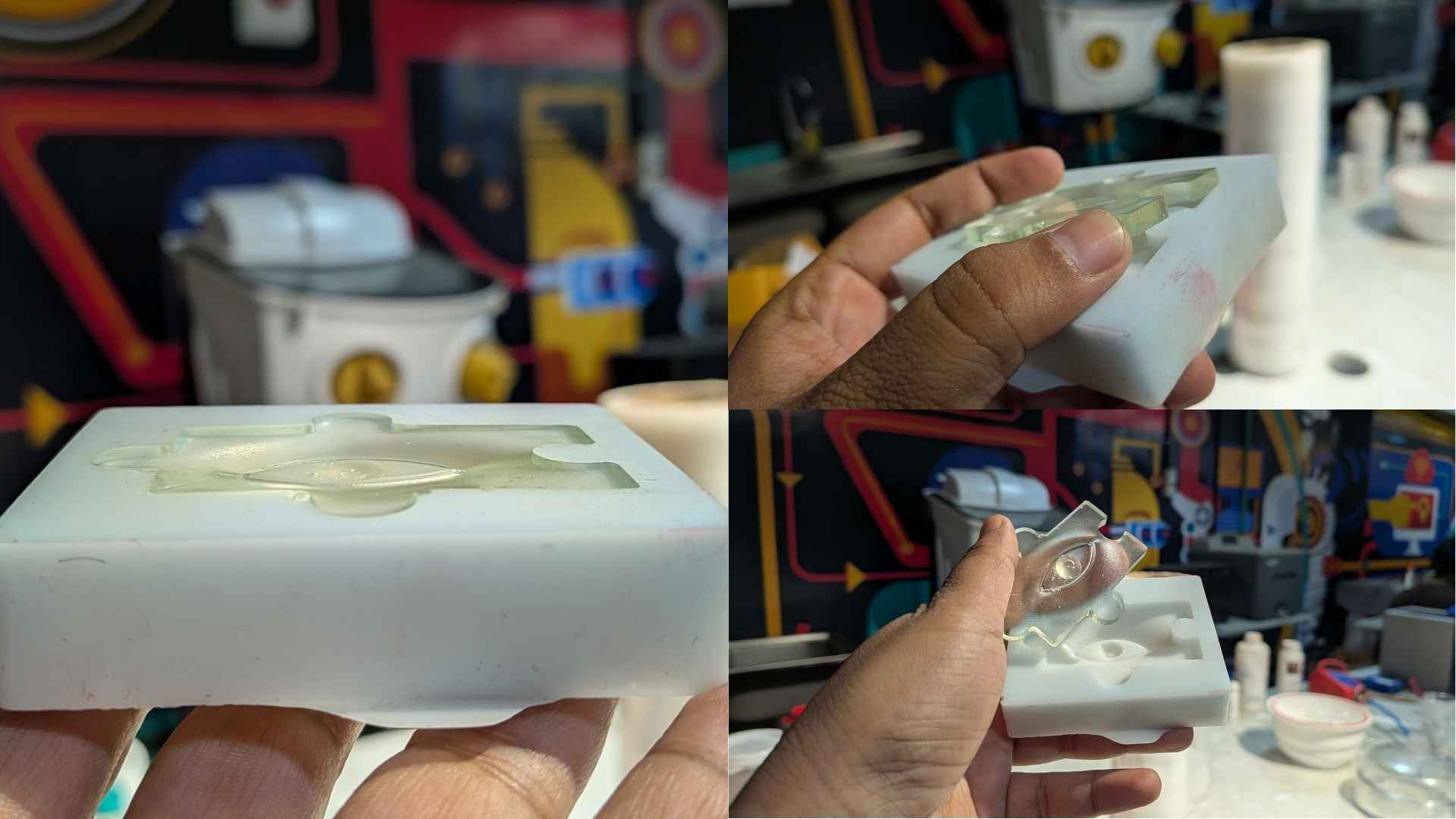
8.Hero Shot - Final Output
The final resin cast successfully replicated the mold geometry, including the embedded eyeball feature. The surface finish was smooth overall, with minor imperfections due to small air bubbles.
Observations
- Accurate measurement of resin components is critical for proper curing
- Slow mixing helps reduce air bubble formation
- Controlled pouring improves surface finish
- Silicone molds allow easy demolding and preserve fine details
Bismuth casting
Bismuth casting is a popular, beginner-friendly metal casting process. Because bismuth has a very low melting point of 271.5°C (520°F) and expands as it solidifies, it can easily be melted on a standard stovetop or hot plate and will perfectly fill complex mold details without shrinkage. (Source: www.instructables.com)
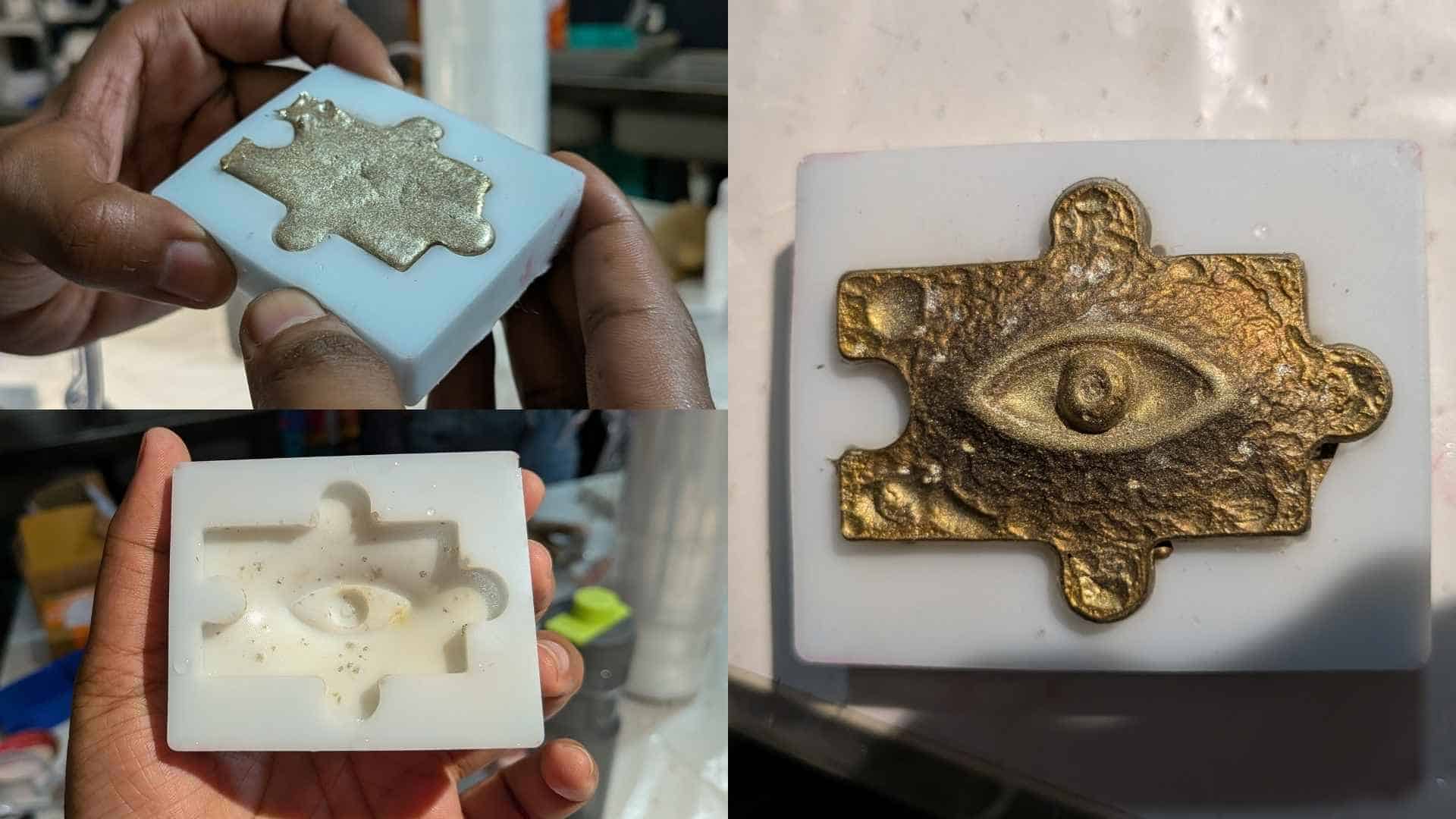
Colour and Surface Finish
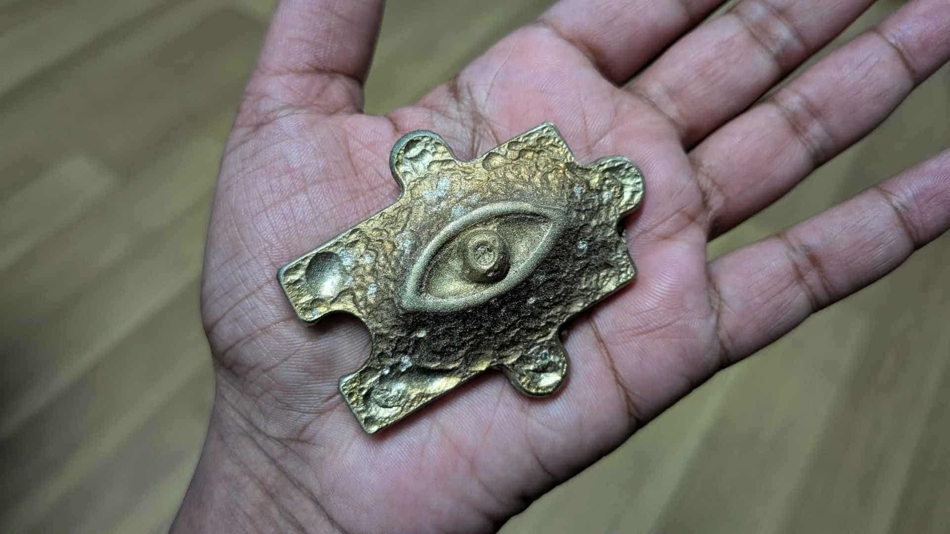
Before casting, we had seen our instructor melting old bismuth castings, which appeared silver in colour. Naturally, we expected my casting to have a similar silver finish. However, when we removed the piece from the silicone mold, everyone was surprised to find that the eye had developed a metallic golden colour instead.
This led me to look into the material a bit more. I learned that while bismuth itself is naturally silver, the colours seen on its surface are influenced by oxidation as the metal cools. Depending on the cooling conditions, different surface colours can appear. In my case, the casting developed a warm gold finish, giving the piece an almost ancient artifact-like appearance.
Design Files
CAD File
CAM Files
Resin Print Files