Week 9: Input Devices
This week explores how microcontrollers receive and interpret information from the physical world through input devices. The focus is on understanding different types of signals and how they can be measured, analyzed, and used in embedded systems.
This week’s instructors were Sibin and Ashish.
Group Assignment
The group assignment involves probing an input device to study its behavior. This includes examining both analog signals (continuous voltage changes) and digital signals (discrete HIGH/LOW states), using measurement tools to understand how these signals vary in response to interaction.
Individual Assignment
The individual assignment focuses on building a functional sensing system. The task is to add a sensor to a self-designed microcontroller board and read its output. This requires interfacing the sensor, acquiring data, and interpreting it meaningfully.
Input Devices
Input devices are components that sense the physical world and send data to a microcontroller. They're how your circuit "feels" what's happening around it.
Without input devices your microcontroller is blind, it can't react to anything. It just runs the same code forever with no awareness of the outside world.
How They Work
Physical world → Input device → Signal → Microcontroller → Response
For example:
You press a button → Button sends signal → XIAO reads it → LED turns on
Types of Input Devices
| Type | Example | Output |
|---|---|---|
| Digital | Button, Hall sensor | HIGH or LOW (0 or 1) |
| Analog | Potentiometer, LDR | Range of values |
| Communication | Camera, IMU | Data over I2C/SPI/UART |
Input Devices - Coin Denomination Detection
This week explored two different input sensing approaches for detecting Indian coin denominations:
1. Vision-Based Detection (Completed)
2. Magnetic Sensing using Hall Effect Sensor (In Progress)
To address limitations of vision-based detection, I started exploring material-based sensing.
Status:
Coin Detection using Vision AI
Overview of Tools and Systems:
Grove Vision AI V2
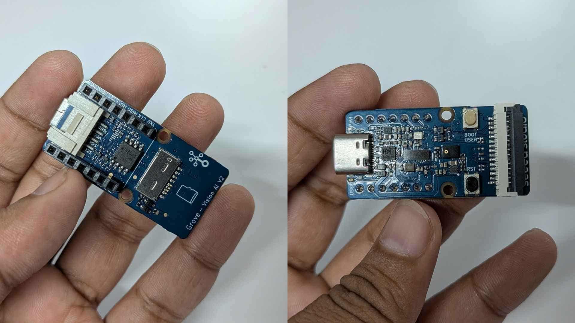
Grove Vision AI V2 is an edge AI module with an onboard processor capable of running TinyML models locally. It supports:
The trained model is exported as a .tflite (TensorFlow Lite) file, which enables efficient on-device inference on resource-constrained hardware like the Grove Vision AI V2.
In this project, it acts as the primary input device, performing on-device classification of coins.
Raspberry Pi Camera (Rev 1.3)
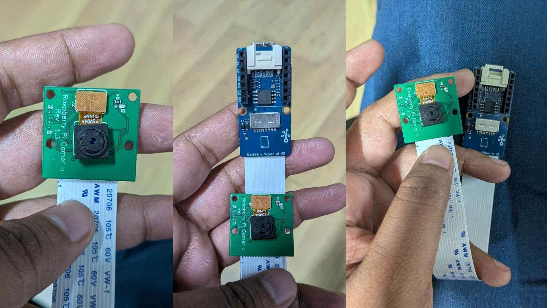
The Raspberry Pi Camera v1.3 is a compact image sensor module used for capturing visual data.
It was used alongside the Grove module to collect training images.
SenseCraft AI (Training Platform)

SenseCraft AI is a no-code/low-code platform for:

Workflow:
What I Did
I trained and deployed an image-based model to classify Indian coin denominations:
Defined multiple classes:
Collected ~20+ images per class under varying orientations and lighting
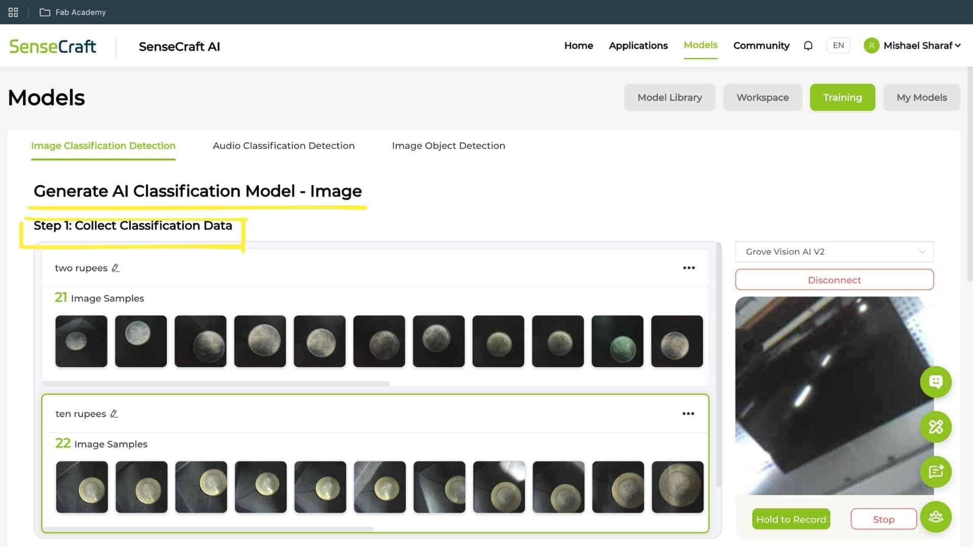
Trained a classification model using Grove Vision AI V2 pipeline
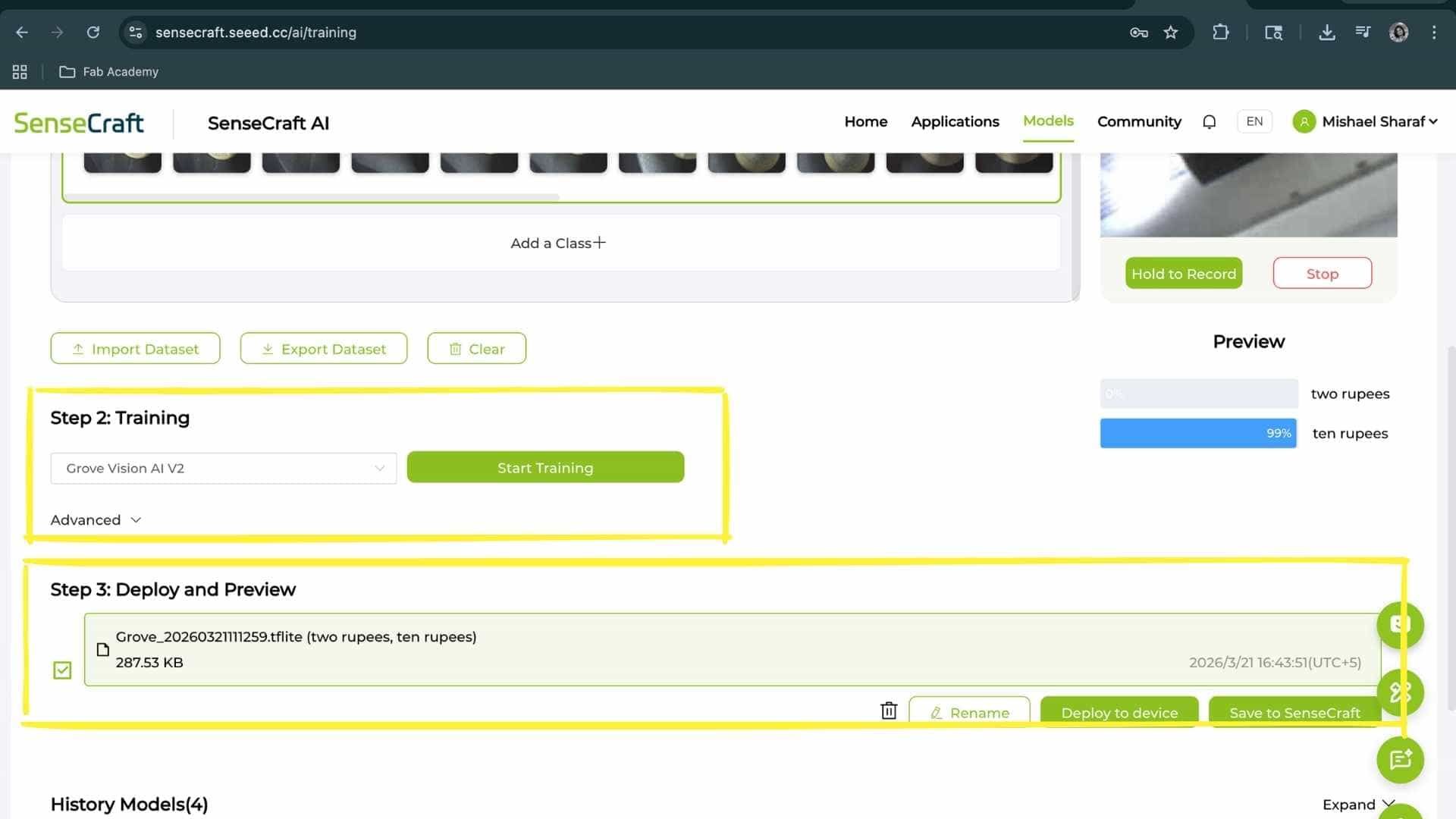
Deployed the trained .tflite model to the device
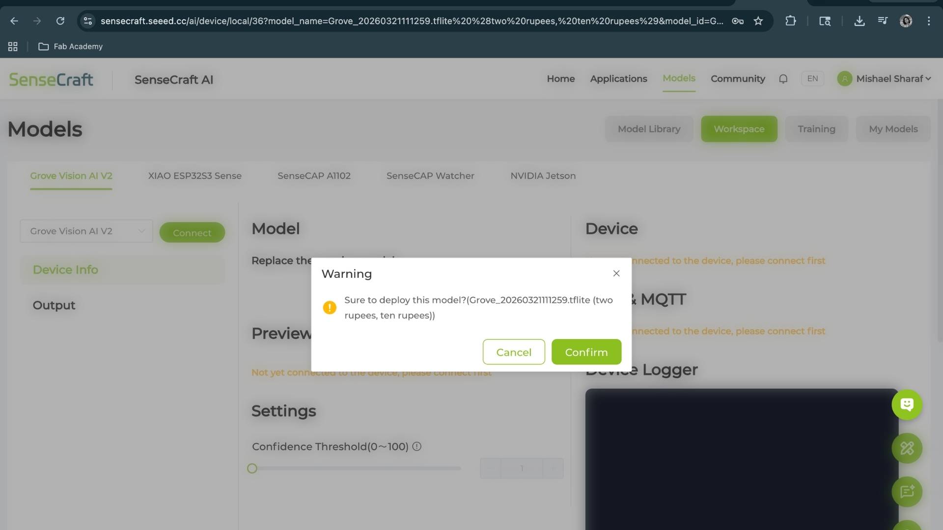
Verified real-time predictions using live camera feed
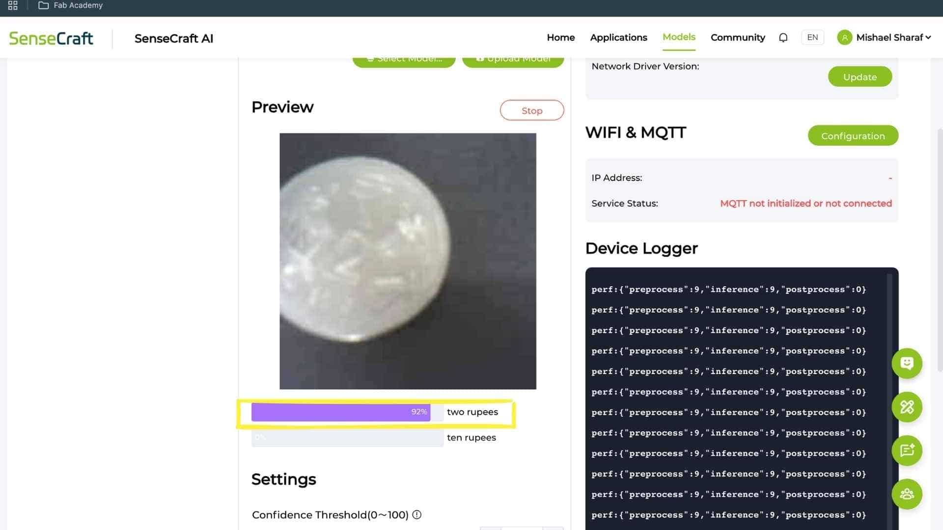
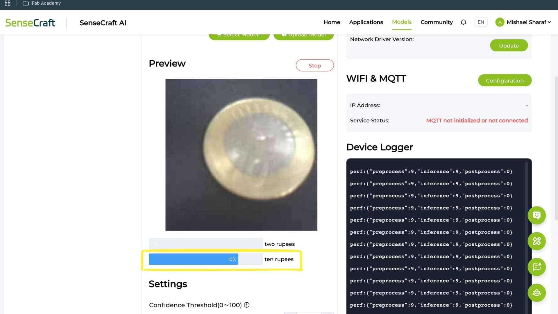
Results
The system successfully detects trained classes:
Key Issues Encountered
1. Camera Limitations
2. Misclassification of Untrained Coins
Example:
Reason:
3. Similar Geometry Problem
₹1 and ₹2 coins:
The model prioritizes:
over semantic features like numbers
What Is Pending / Needs Improvement
Conclusion
This experiment demonstrates that Vision AI can function as an input device, but reliability depends on:
For applications like a smart piggy bank, vision alone is insufficient for distinguishing similar coins. Maybe a multi-sensor approach is required for robust performance.
Hall Effect Sensor
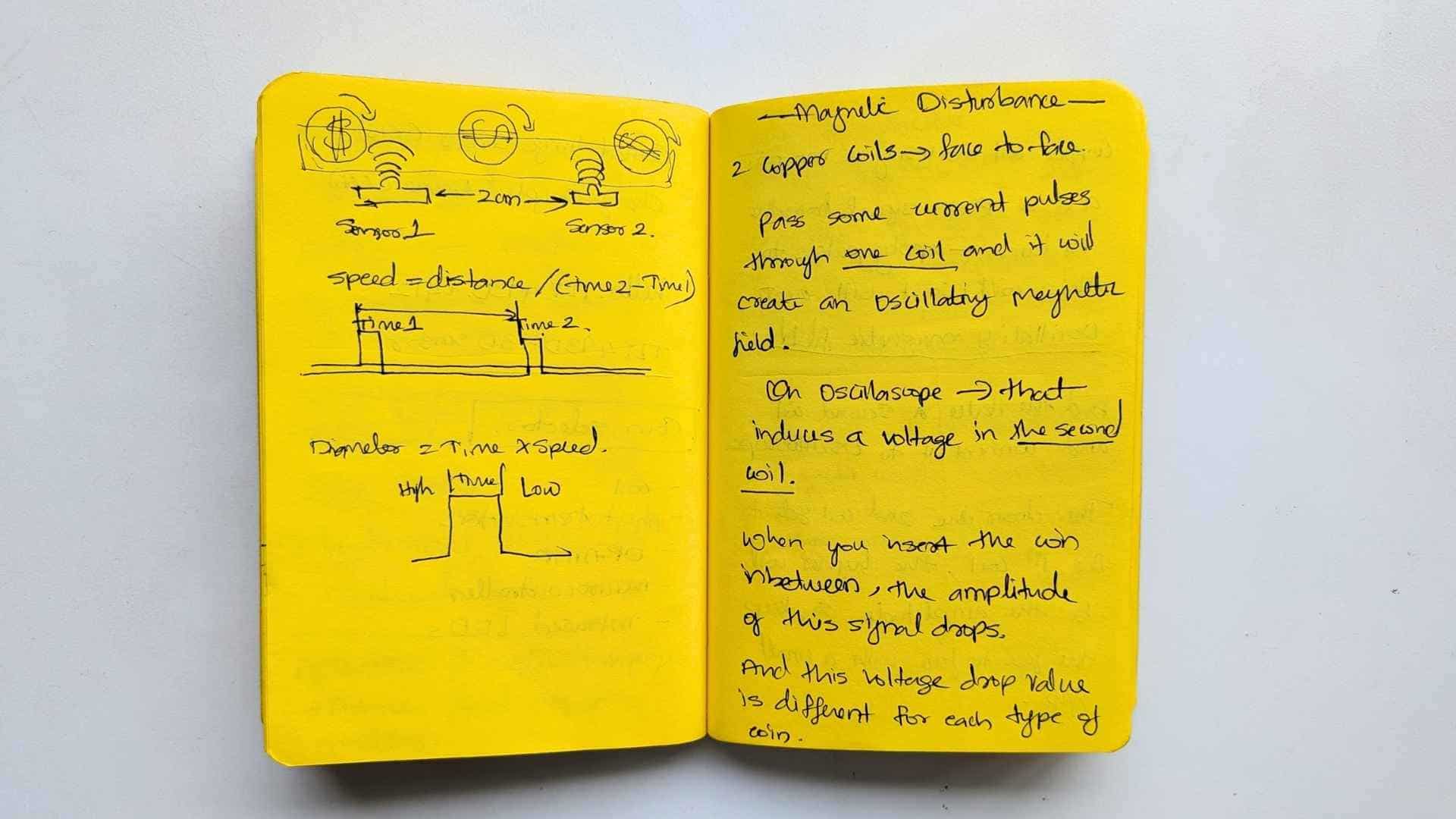
While trying to understand how industrial coin acceptors work, I came across a youtube video explaining different sensing methods. From what I understood, they use parameters like speed and diameter, and also rely on magnetic disturbance using coils to detect voltage changes. The video mentioned that a similar effect could be measured using a Hall effect sensor (though slower), which led me to explore that direction.
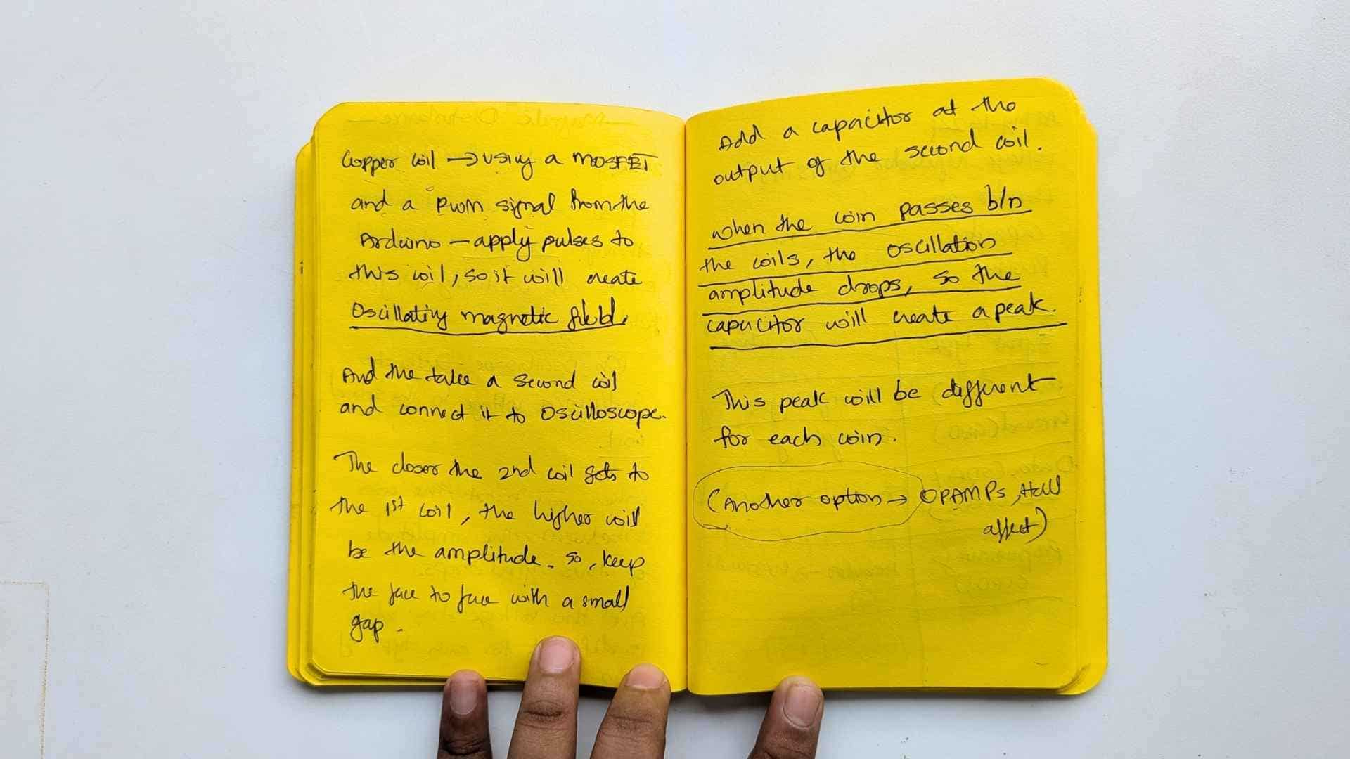
That’s how I ended up working with a Hall effect sensor.
Understanding the different Hall Effect Sensors
In physics and engineering, the term vector Hall effect typically refers to one of three advanced applications of the Hall effect where the directional (vector) nature of physical fields-ike magnetic fields, light polarization, or thrust-is manipulated or measured:
1. Vector Magnetic Field Sensing
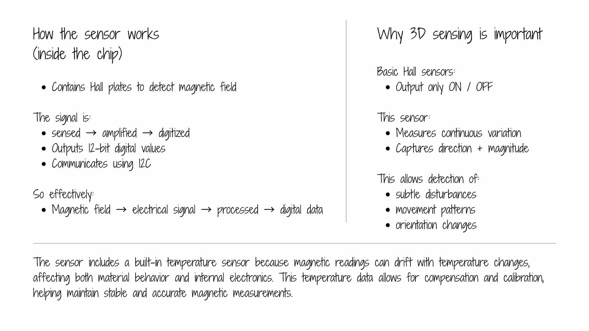
Traditional Hall sensors measure only the component of a magnetic field perpendicular to the sensor's surface. A vector Hall sensor (often a 3D magnetometer) uses multiple Hall elements oriented on three orthogonal planes to uniquely determine the full magnetic field vector, including its magnitude and 3D direction.
2. Optical Vector-Mode Hall Effect
In photonics, the spin Hall effect of light describes how the two spin components (right-handed and left-handed circular polarization) of a light beam split in opposite transverse directions.
3. Hall-Effect Thruster (HET) Vectoring
In aerospace, Hall-effect thrusters use a magnetic field to trap electrons, creating an electric field that accelerates ions to produce thrust.
Comparison of Vector vs. Standard Hall Effect
| Feature | Standard Hall Effect | Vector Hall Effect (General) |
|---|---|---|
| Measurement | Single scalar value (voltage) | Full vector (magnitude & direction) |
| Application | Simple proximity/current sensing | 3D mapping, light steering, spacecraft propulsion |
| Complexity | Single sensing element | Multiple elements or segmented structures |
Why a Vector Hall Sensor Was Used
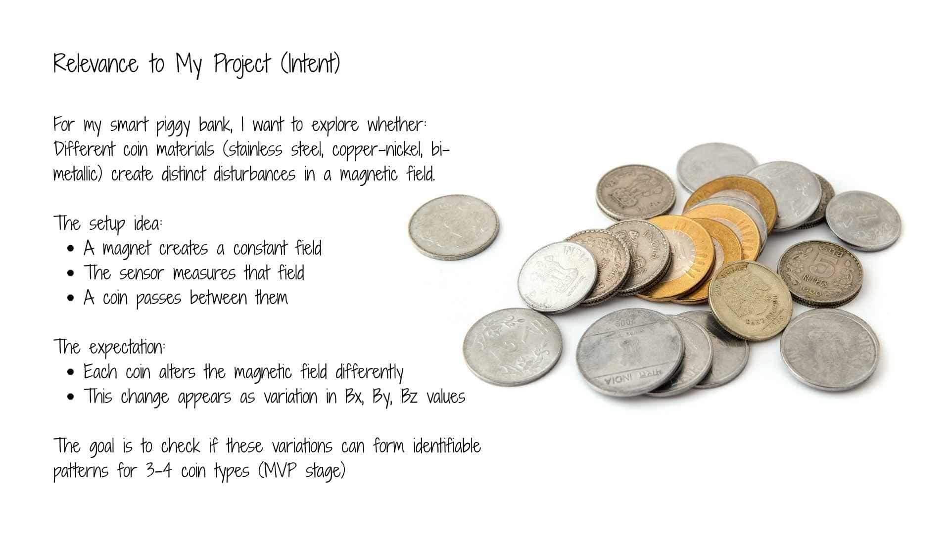
A vector Hall sensor was chosen to explore magnetic disturbance as a measurable input, rather than just detecting the presence of a magnetic field.
In this project, the goal is not simply to detect a magnet, but to observe how a coin affects the magnetic field between a magnet and the sensor. This interaction is subtle and depends on the material and position of the coin.
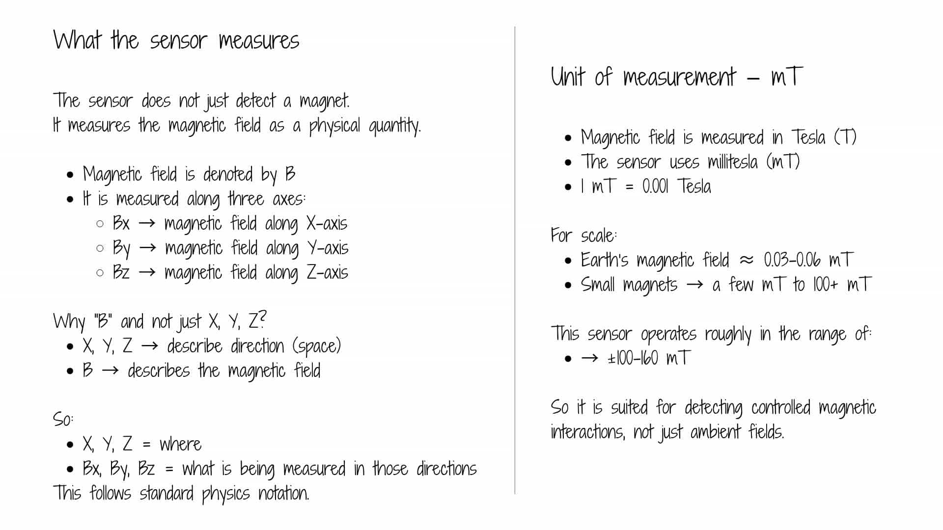
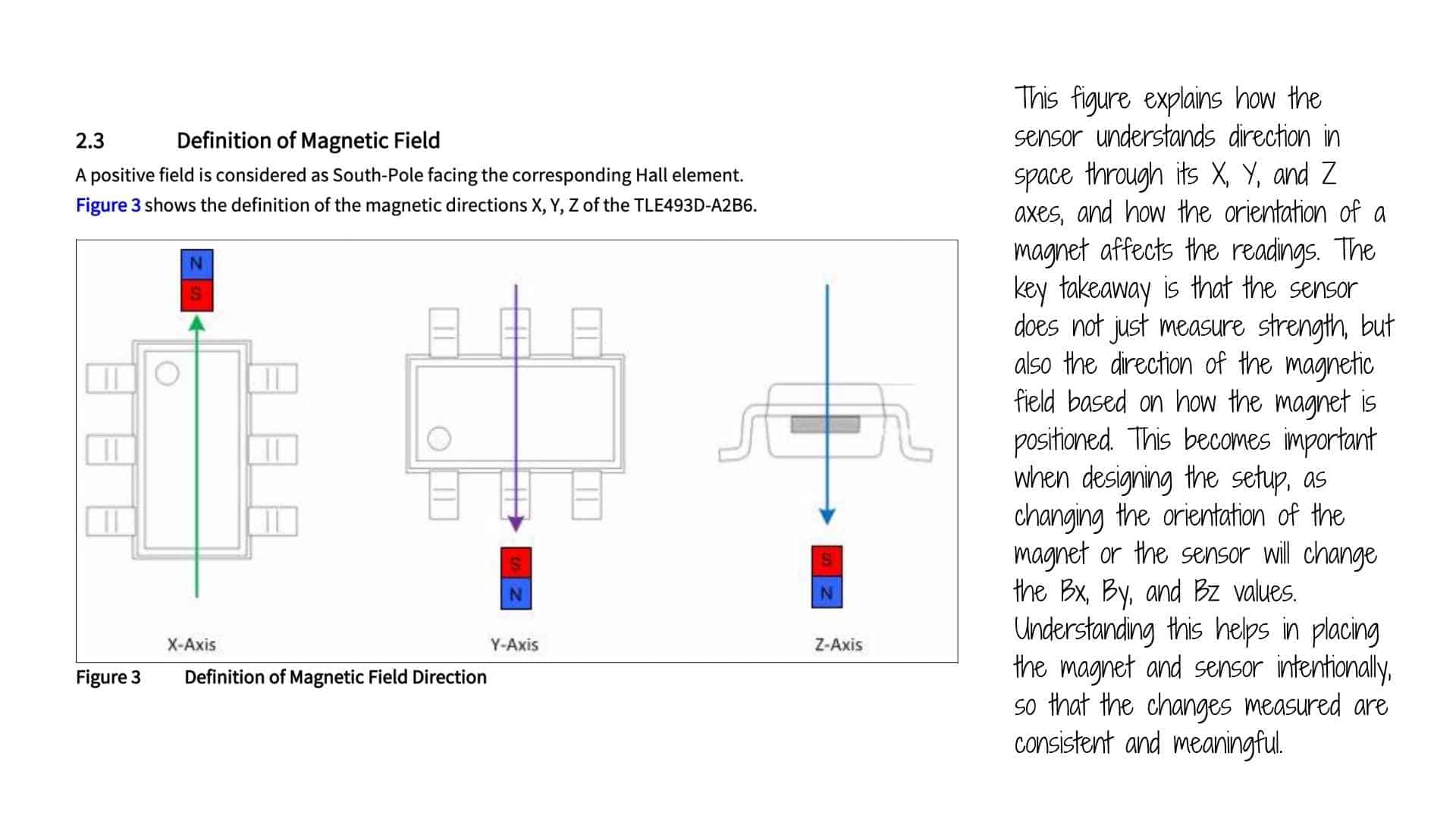
A standard Hall sensor provides only a single value (field strength), which is often insufficient to capture these small variations. In contrast, a vector Hall sensor measures the magnetic field along three axes (X, Y, Z), allowing a more detailed understanding of how the field is being distorted.
This makes it possible to:
Additionally, using a vector sensor keeps the system open for further exploration, such as position sensing or interaction-based inputs, without redesigning the hardware.
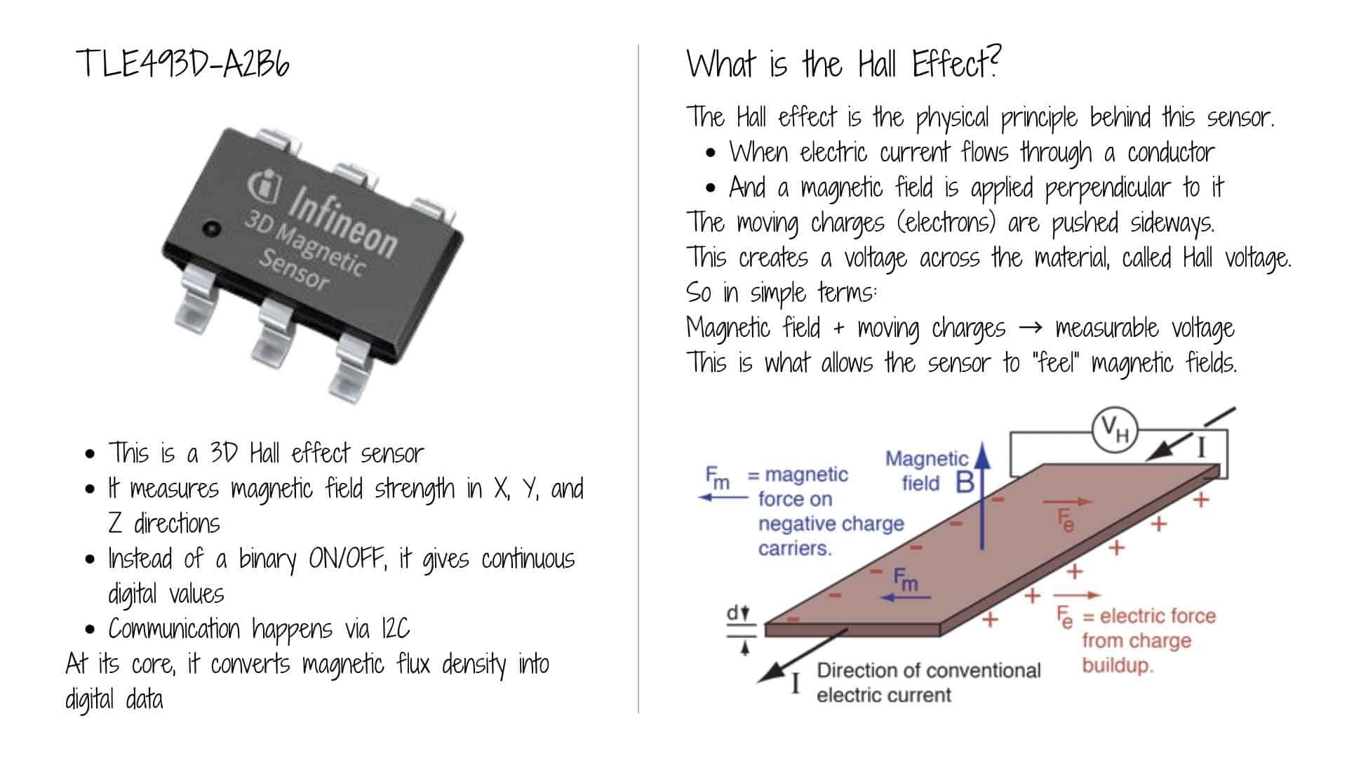
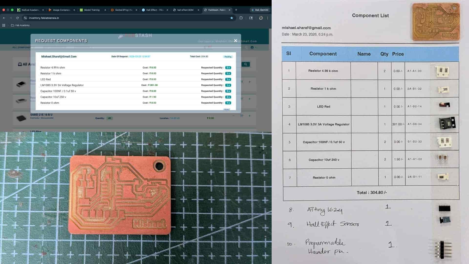
TLE493D-A2B6
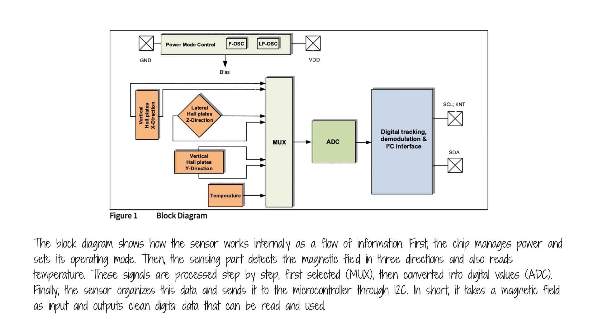
The TLE493D-A2B6 is a low-power 3D magnetic sensor from Infineon Technologies designed for high-precision three-dimensional sensing in automotive and industrial applications. It detects the magnetic flux density along the X, Y, and Z axes using Hall effect technology, making it ideal for tracking complex movements like joysticks, control knobs, and gear stick positions.
Key Specifications
Primary Applications
ATtiny1624
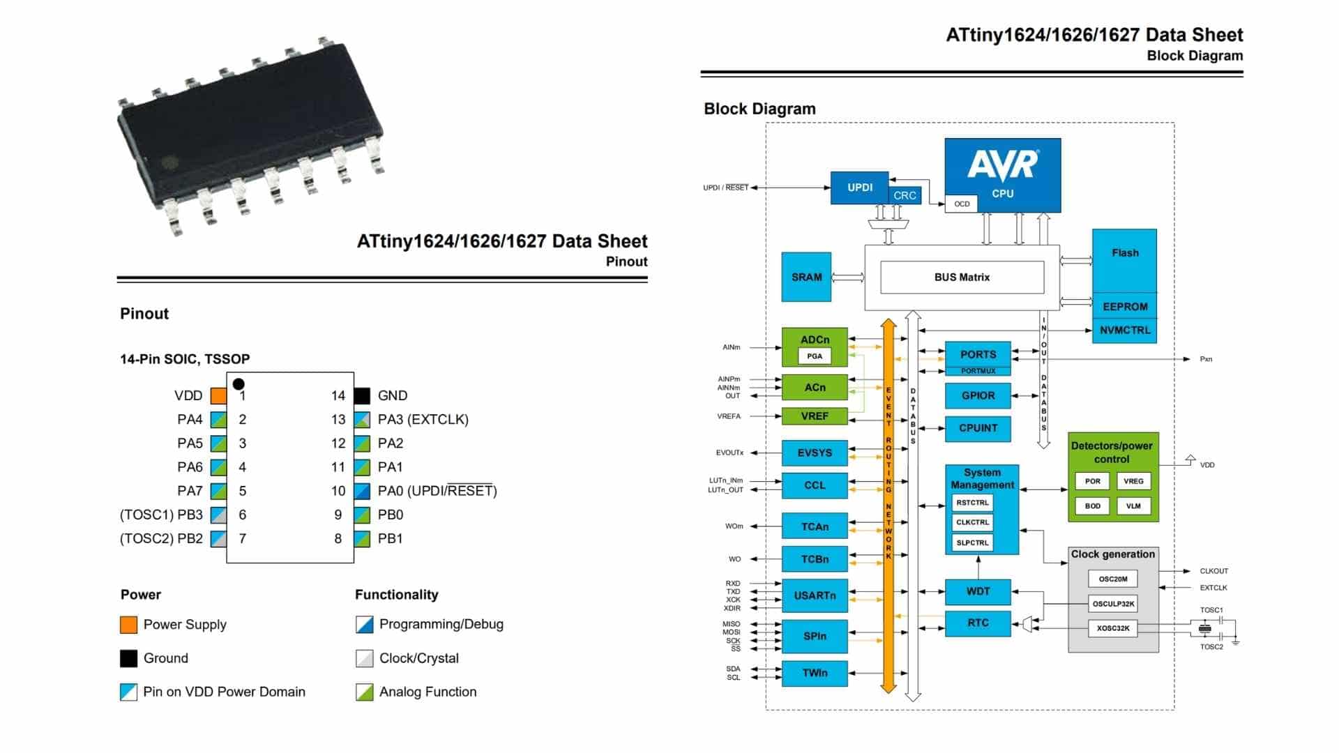
The ATtiny1624 is a compact 8-bit microcontroller from Microchip’s AVR family, designed for low-power and embedded control applications. It belongs to the tinyAVR 1-series, offering a balance of simplicity and modern peripheral features.
At its core, it uses an AVR CPU running up to 20 MHz, with 16 KB of Flash memory, 2 KB SRAM, and 256 bytes of EEPROM. This makes it suitable for small to moderately complex embedded tasks such as sensor interfacing, control systems, and educational prototypes.
The chip provides multiple peripherals and communication interfaces, including:
It also features UPDI (Unified Program and Debug Interface), which simplifies programming and debugging using a single pin.
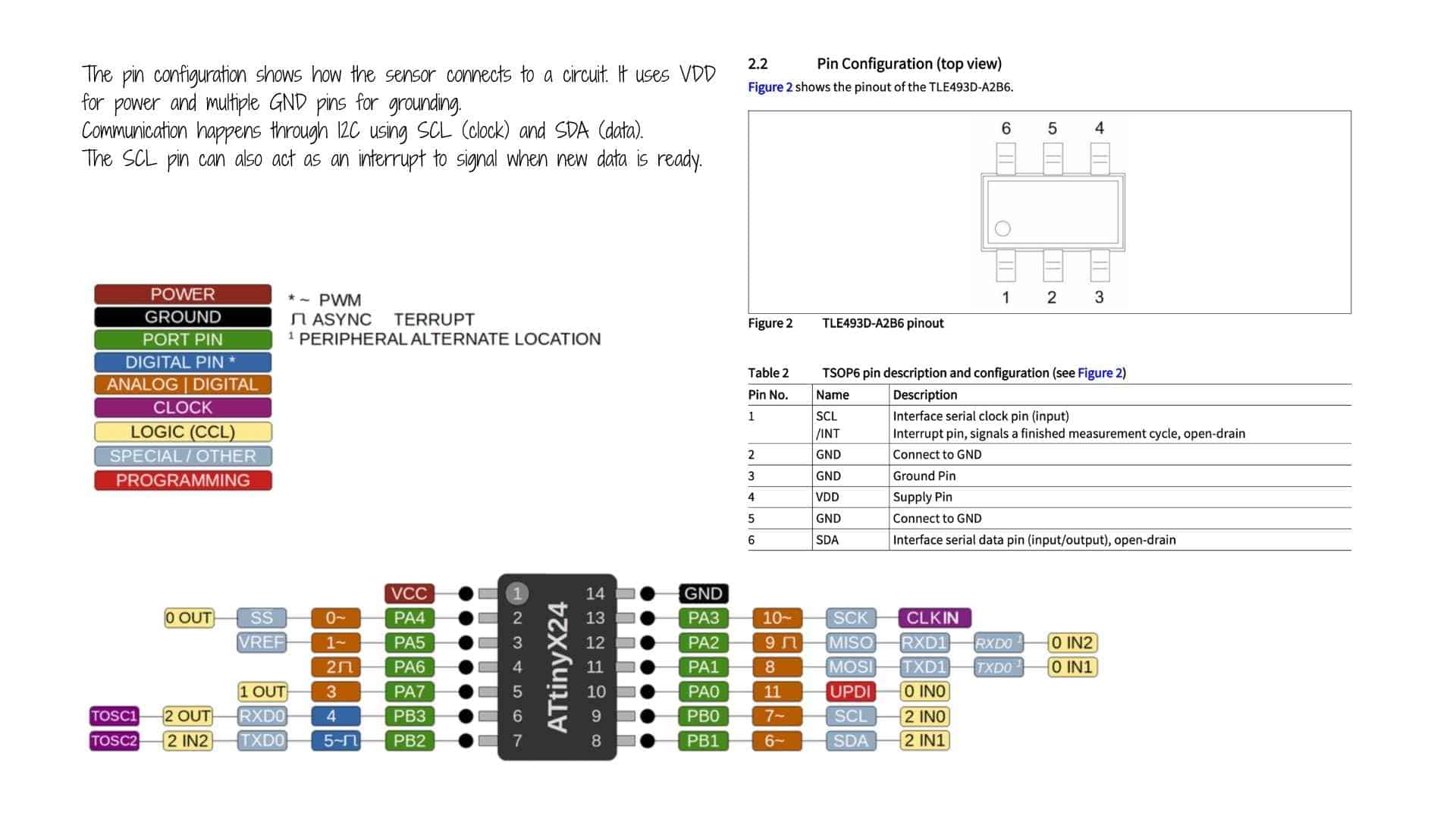
In the 14-pin package, it offers a limited but flexible set of GPIO pins, many of which support multiple functions (analog input, communication lines, clock pins, etc.), allowing efficient pin usage in compact designs.
Overall, the ATtiny1624 is well-suited for low-cost, space-constrained, and low-power embedded systems, especially where moderate processing and peripheral integration are required.
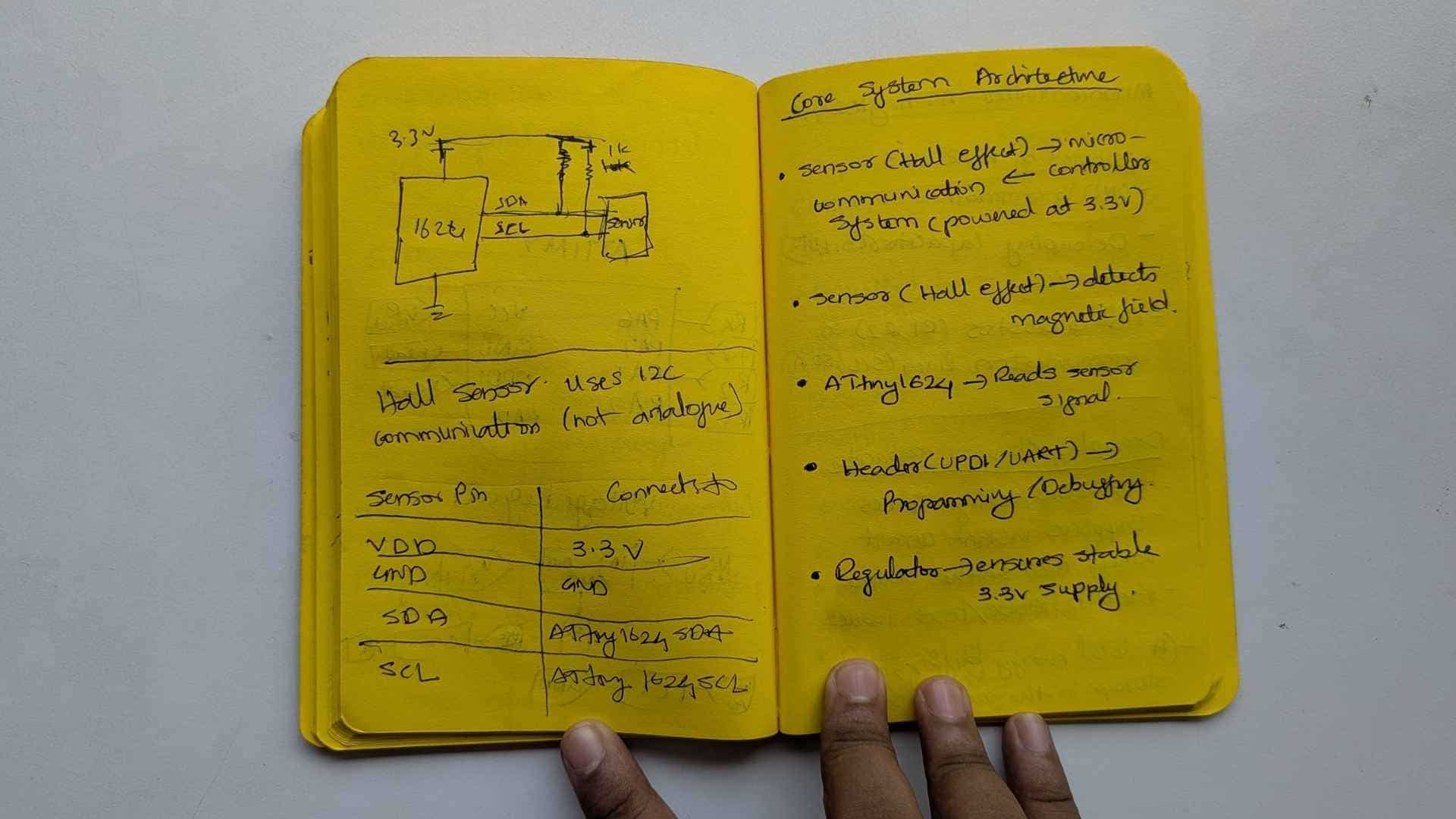
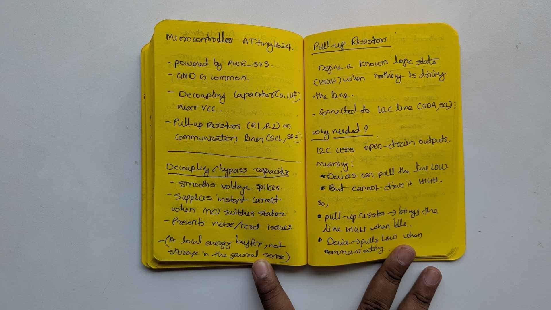
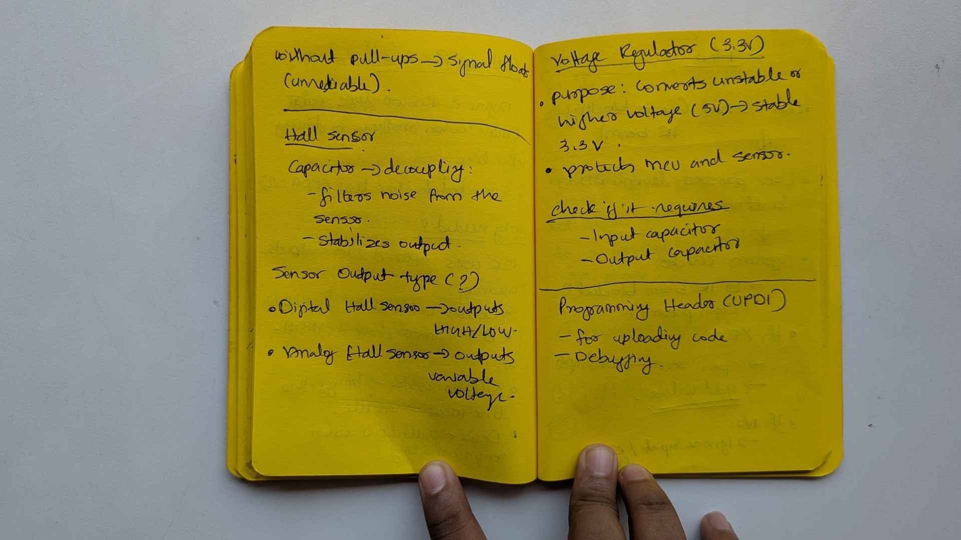
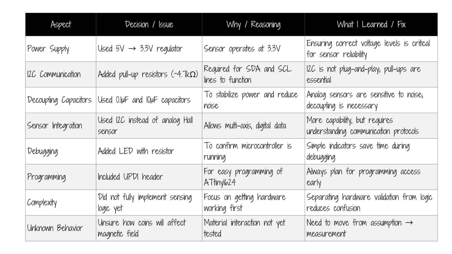
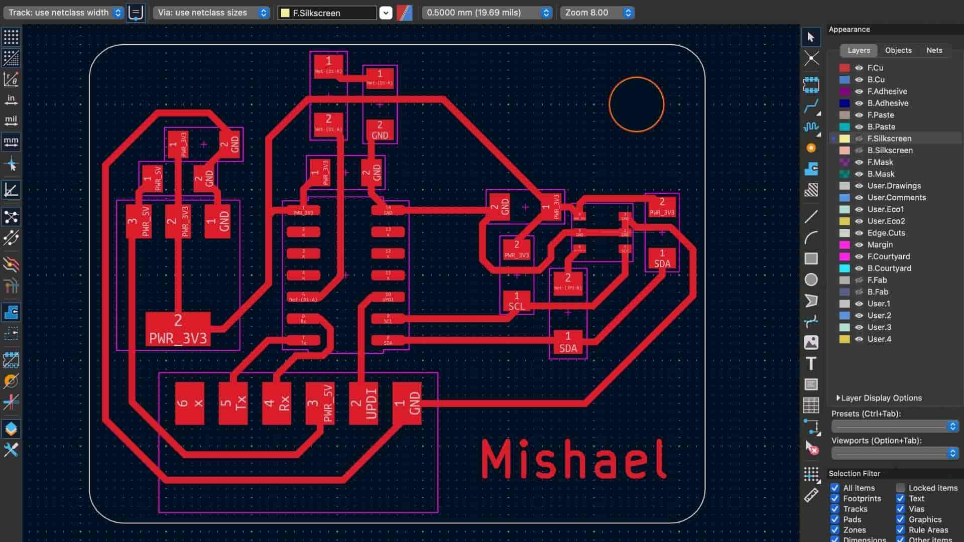
Notes: Understanding the circuit
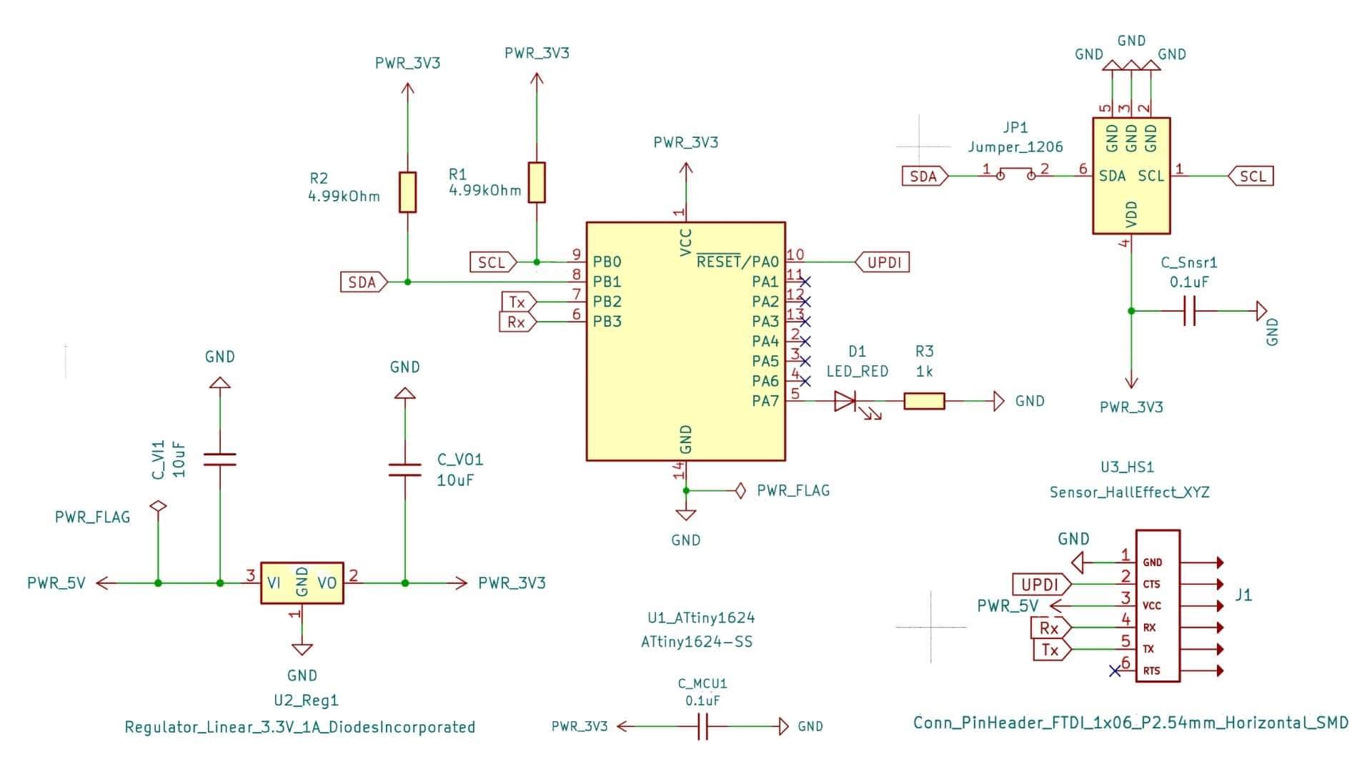
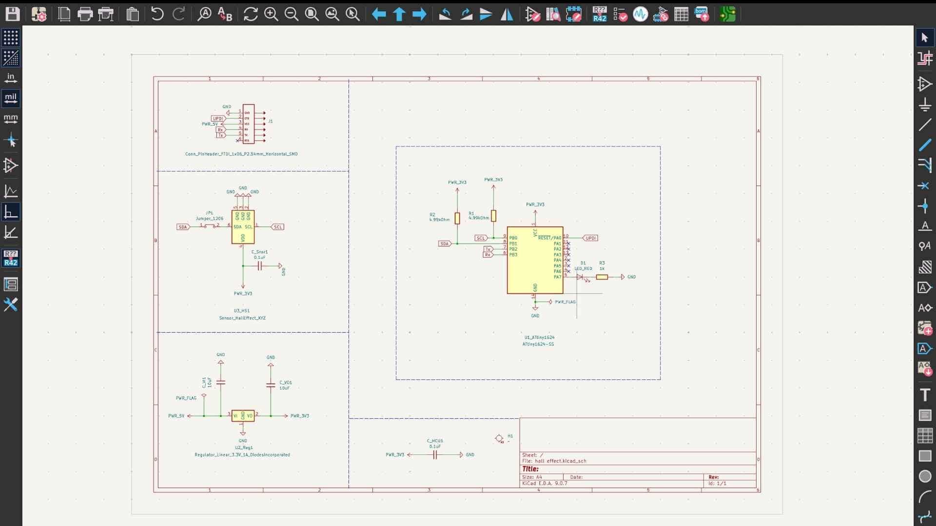
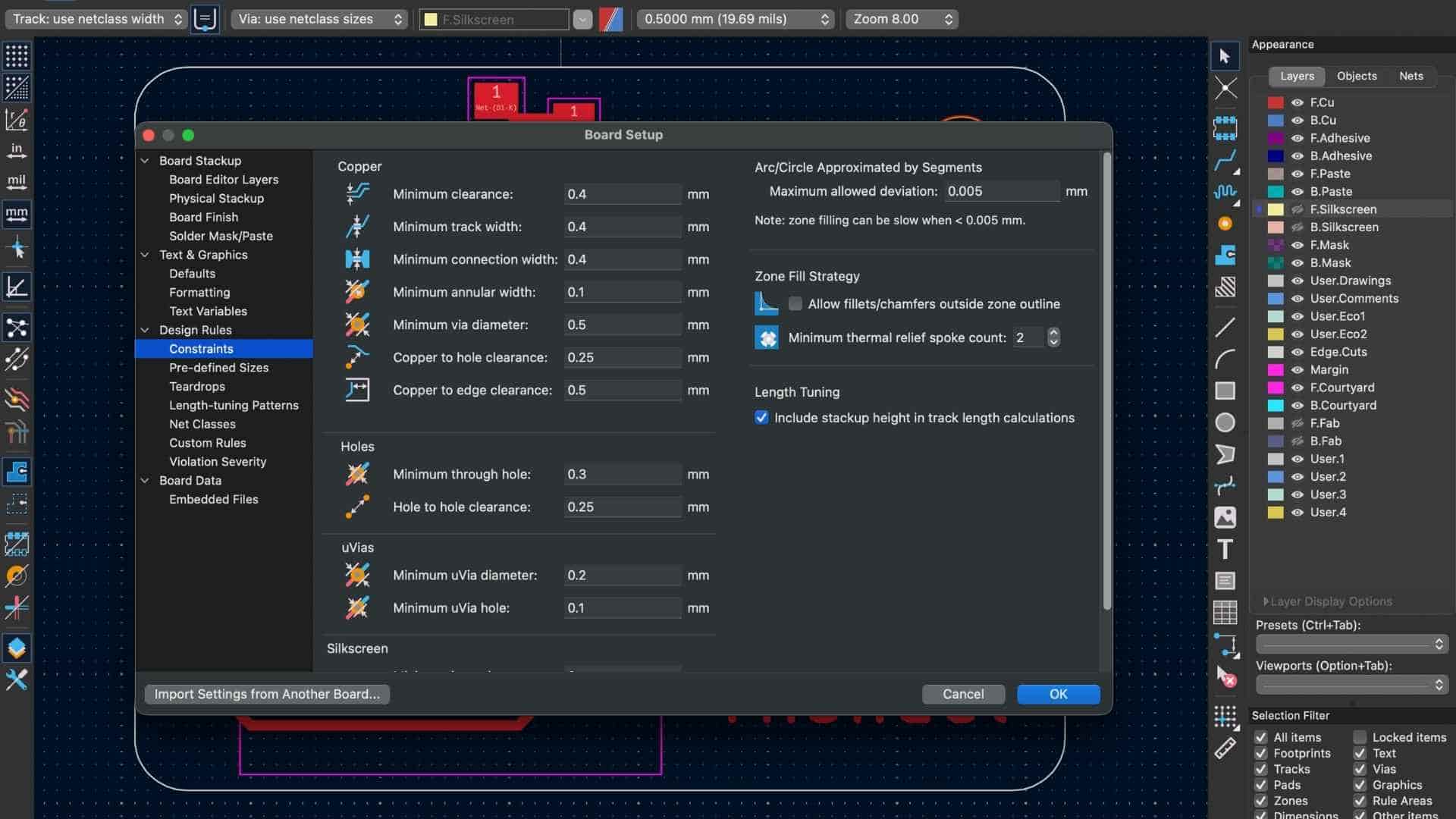
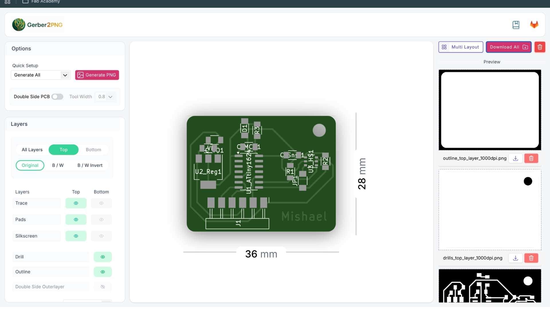
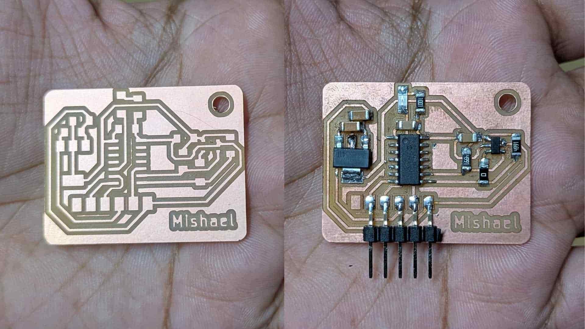
PCB Schematic
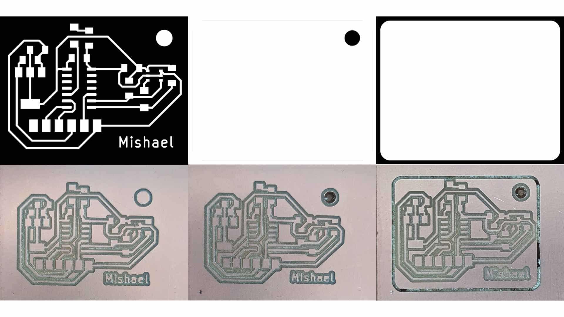
Soldering (Stop-motion)
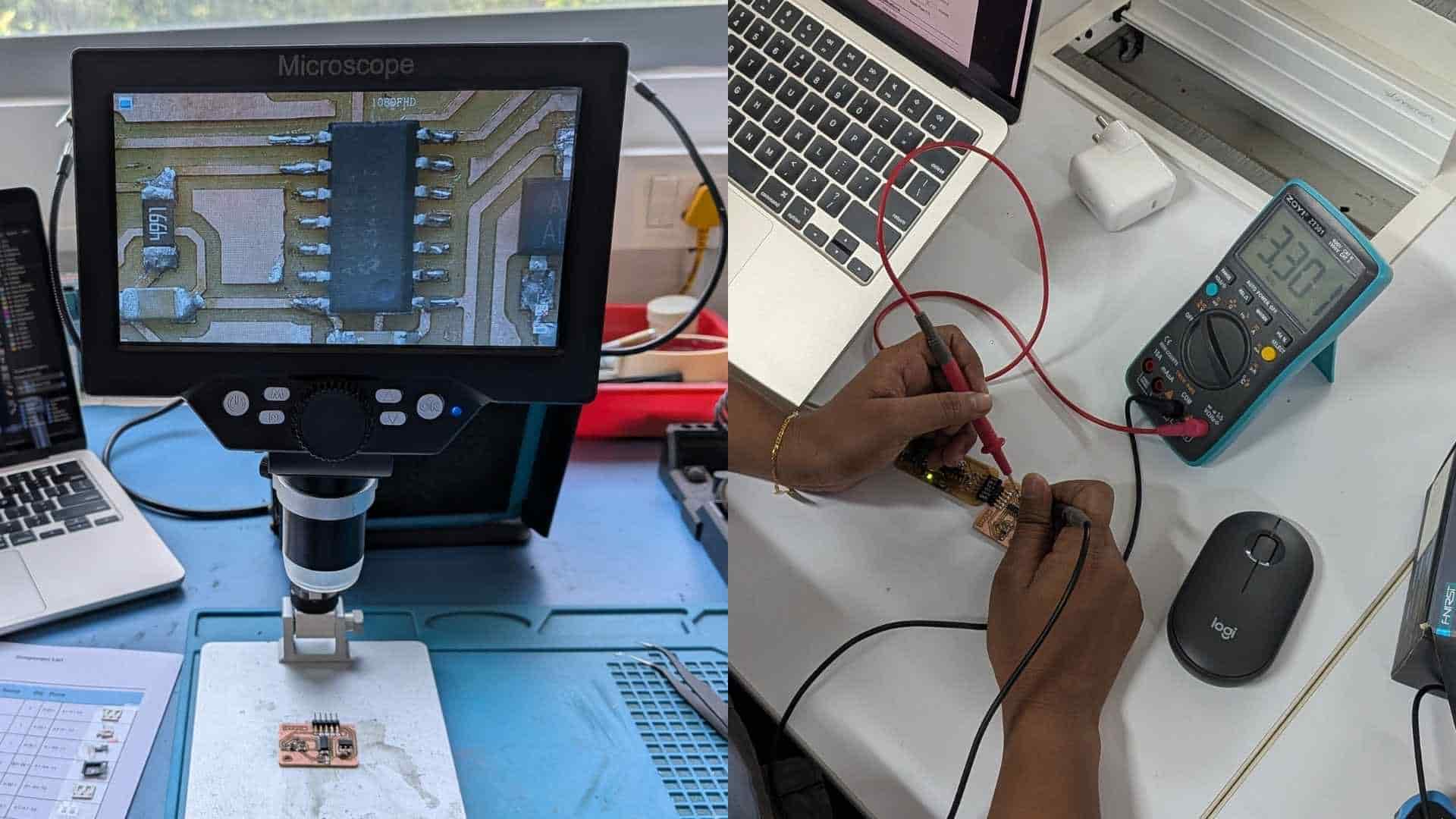
Testing & Debugging
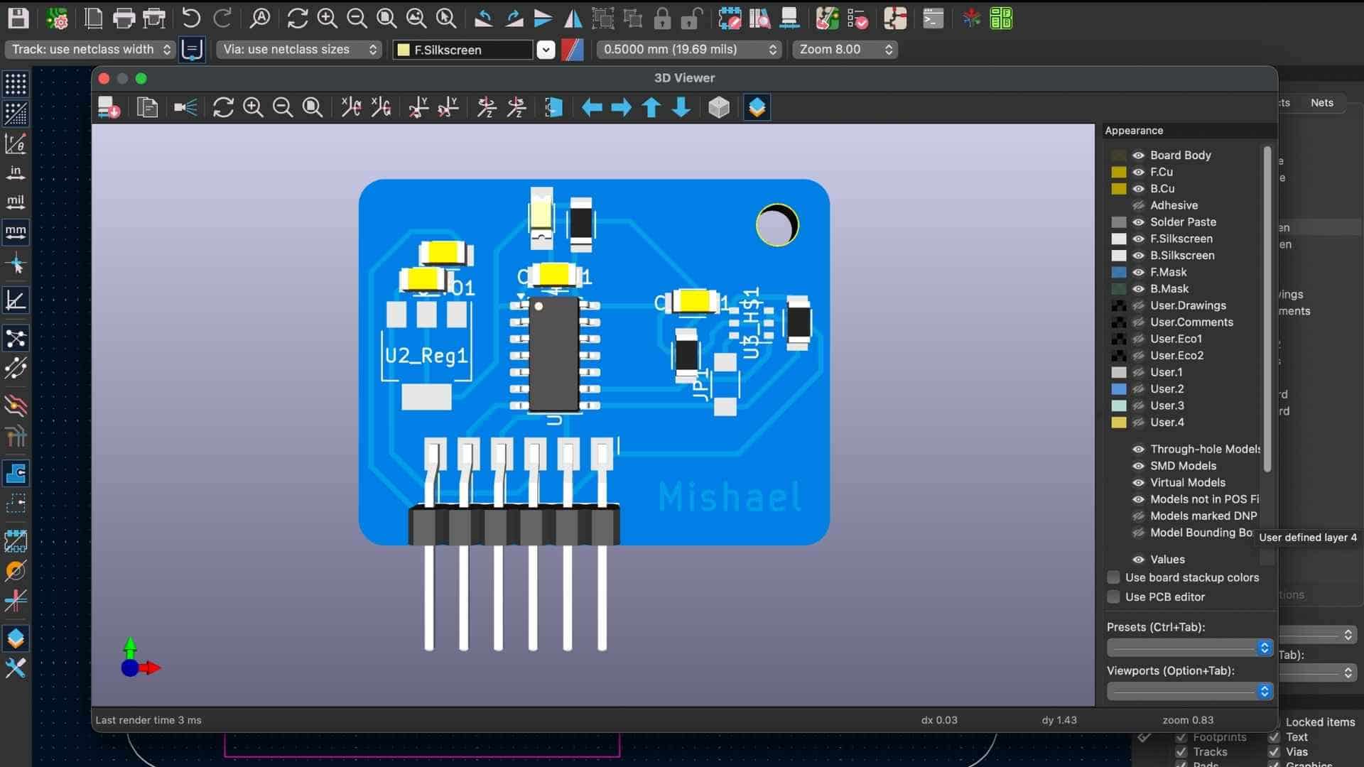
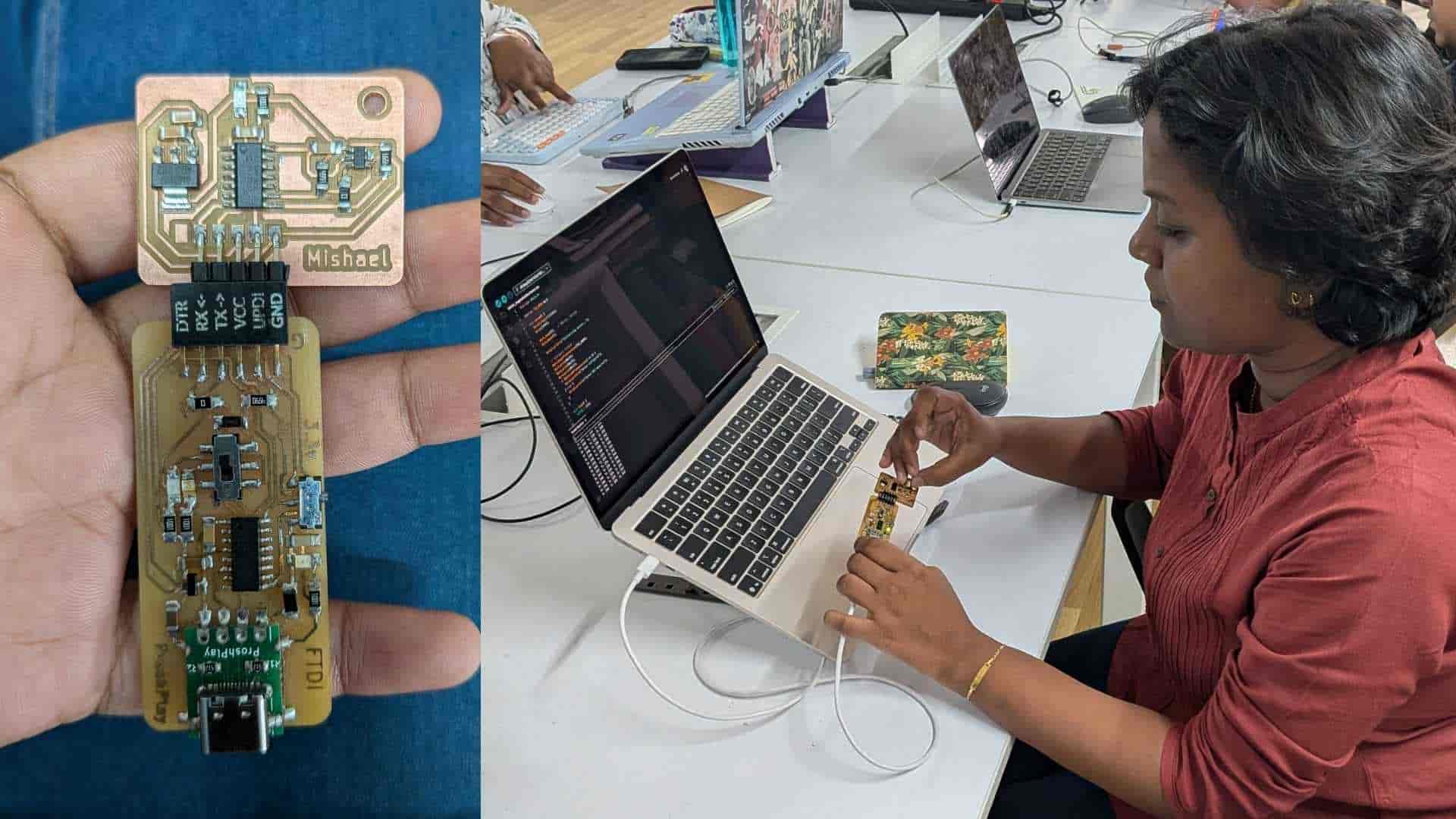
Hero Shot
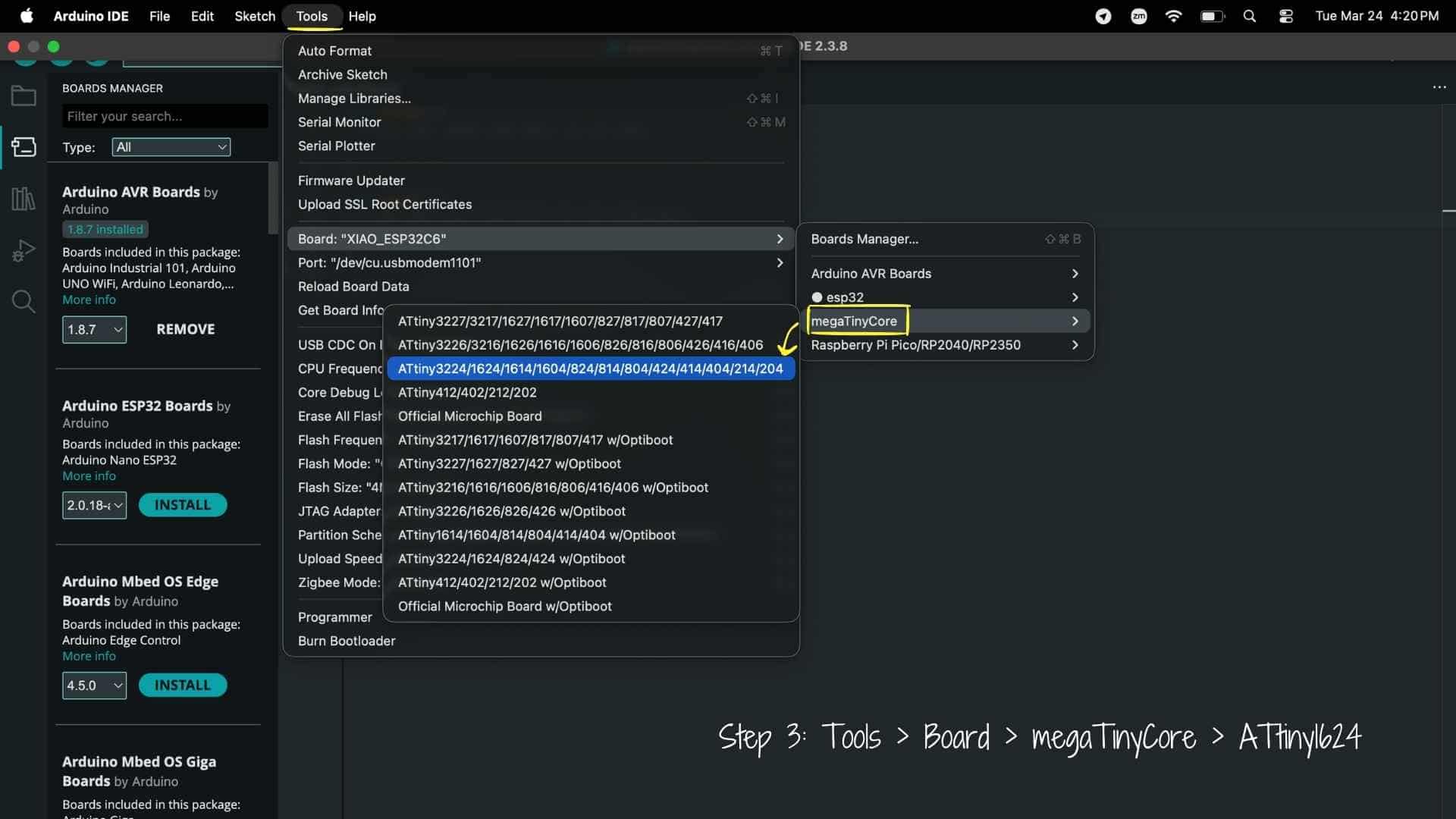
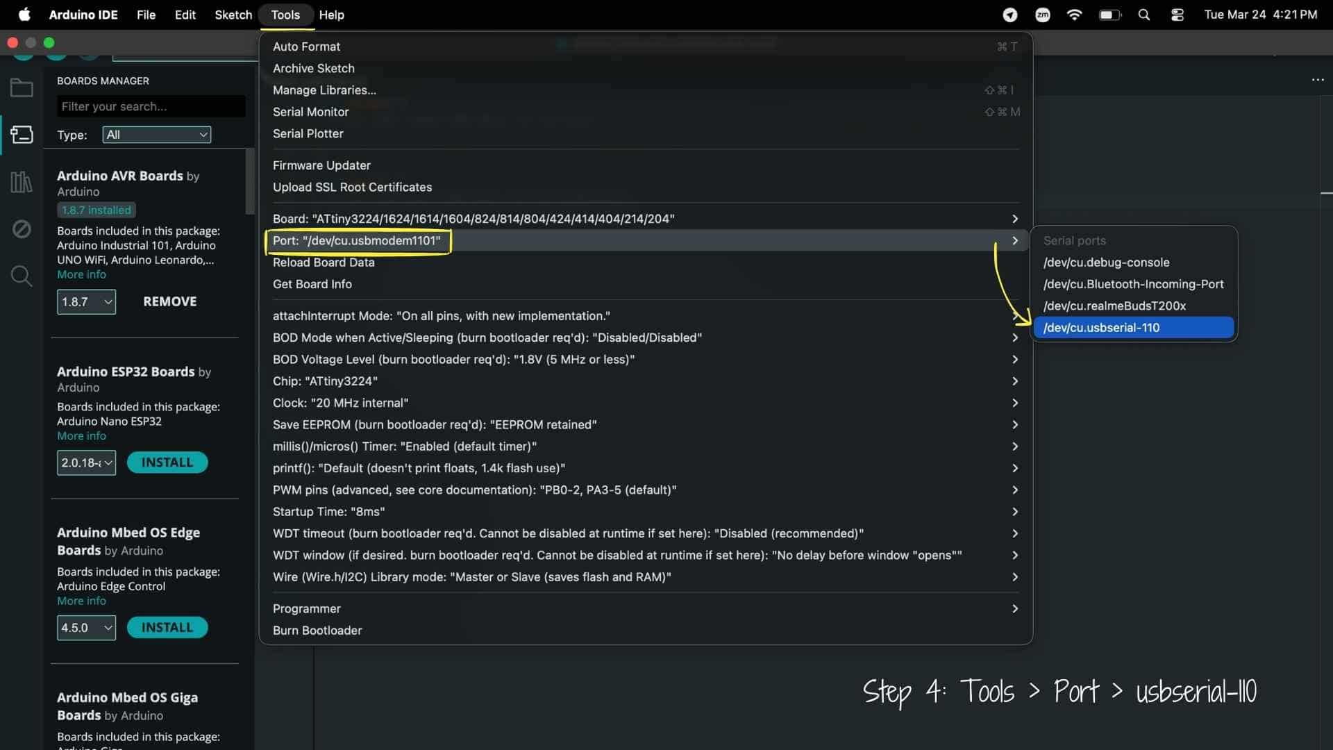
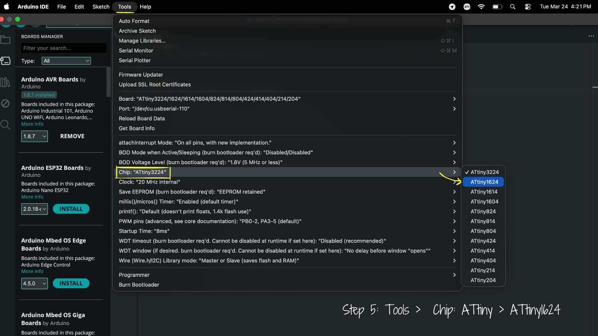
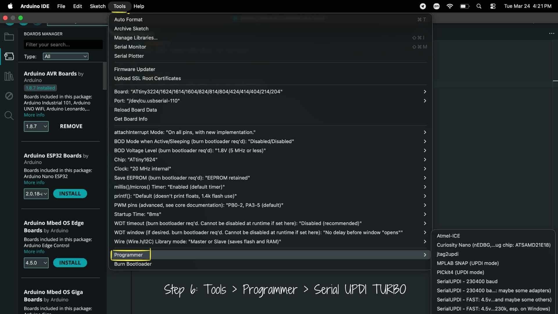
Programming with Arduino IDE
Before testing the sensor, I needed to first install board manager for ATtiny1624. These were the steps followed:
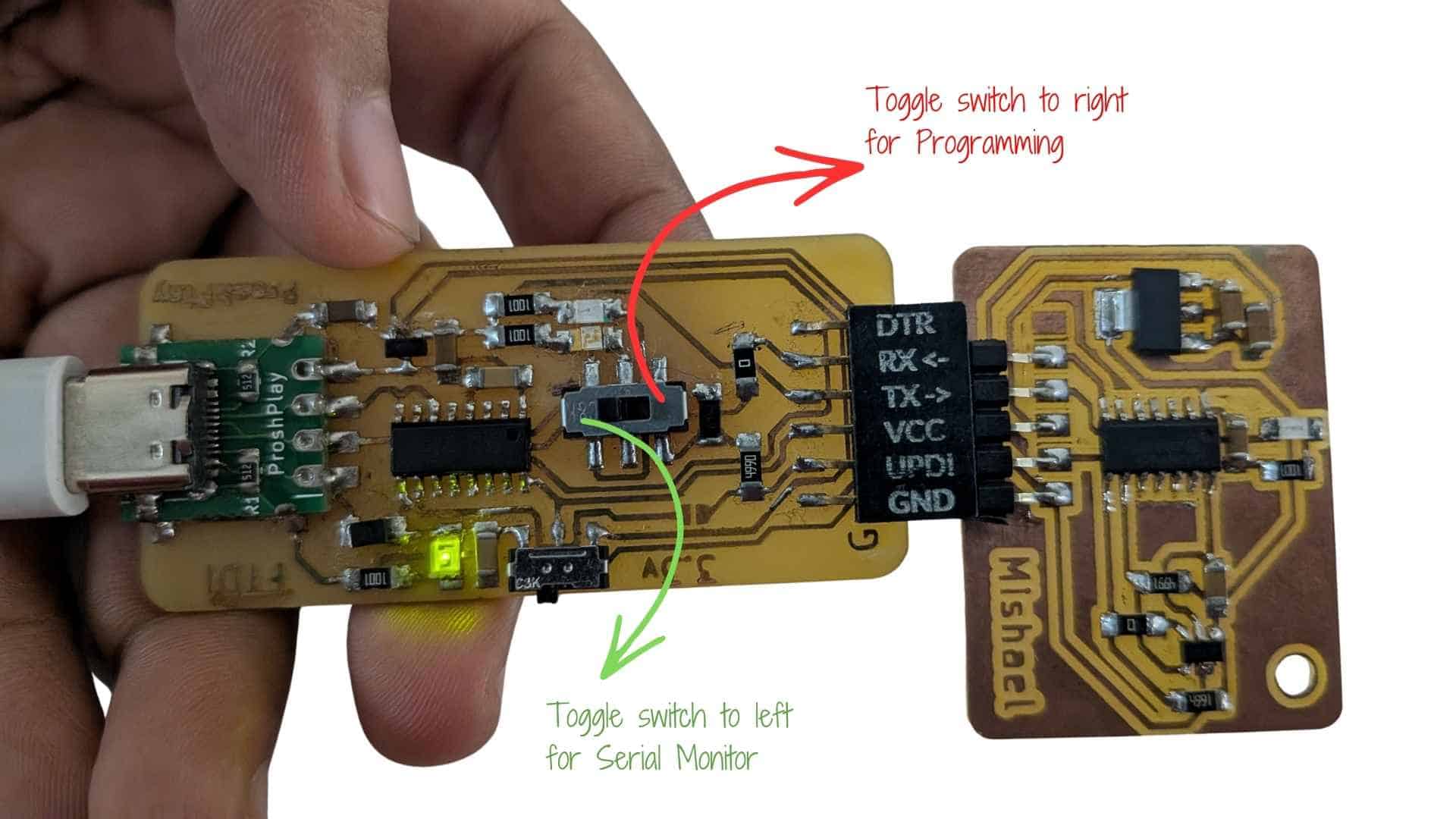
Using Type-C CH340C UPDI + FTDI Converter for ATtiny1624
Reference for FTDI-UPDI Converter
1. What I Used
2. About the Converter
This board combines two functionalities:
The CH340C chip acts as a USB-to-serial bridge, allowing communication between the computer and microcontroller over UART
Key features:
3. Working Principle
The converter operates in two modes:
1. UPDI Mode (Programming)
2. UART Mode (Serial Monitoring)
Because both functions share the same USB interface, the board requires switching between modes (hardware-level routing).
Blink test
  // Define the LED pin
#define LED_PIN PIN_PA7   // Change this to your actual pin

void setup() {
  pinMode(LED_PIN, OUTPUT);
}

void loop() {
  digitalWrite(LED_PIN, HIGH); // LED ON
  delay(1000);                 // 1 second
  digitalWrite(LED_PIN, LOW);  // LED OFF
  delay(1000);                 // 1 second
}
Serial Monitor Test
  void setup() {
  Serial.begin(115200);
  delay(2000);
  Serial.println("HELLO FROM ATTINY");
}

void loop() {
  delay(2000);
  Serial.println("HELLO FROM ATTINY");
}
TLE493D Magnetic Field Measurement Test (Ambient vs Applied Magnet)
Prompt used on chatGPT:
I am using a TLE493D-A2B6 magnetic field sensor with an ATtiny1624 over I²C and would like to do a basic functionality test to confirm that the sensor is responding correctly.

Can you help me write a simple program that:

Initializes the TLE493D sensor over I²C.
Reads the magnetic field data continuously.
Prints the X, Y, and Z values to the Serial Monitor.
Keeps the code simple and easy to understand for testing purposes.
Includes comments explaining each step.

The goal is to observe how the sensor values change when a magnet is brought close to the sensor and verify that the sensor is detecting magnetic field variations before moving on to more advanced processing.
#include <
Wire.h> #define TLE_ADDR 0x35 void setup() { Serial.begin(115200); delay(1000); // give time to open serial monitor // IMPORTANT: match your hardware pins (PB0=SCL, PB1=SDA) Wire.swap(0); Wire.begin(); // Configure sensor (same as Neil’s reference) Wire.beginTransmission(TLE_ADDR); Wire.write(0x10); Wire.write(0x28); // config Wire.write(0x15); // mode Wire.endTransmission(); Serial.println("TLE493D ready..."); } void loop() { uint8_t b[6]; // Request 6 bytes from sensor Wire.requestFrom(TLE_ADDR, 6); if (Wire.available() == 6) { for (int i = 0; i < 6; i++) { b[i] = Wire.read(); } // Very basic interpretation (not full precision yet) int x = b[0]; int y = b[1]; int z = b[2]; Serial.print("X: "); Serial.print(x); Serial.print(" Y: "); Serial.print(y); Serial.print(" Z: "); Serial.println(z); } else { Serial.println("Sensor not responding"); } delay(200); }
Magnetic Sensing with TLE493D
I interfaced a TLE493D-A2B6 with my ATtiny1624 using I²C and used a USB–UART/UPDI converter for programming and serial monitoring. I initially used Neil’s code to test the sensor, but I couldn’t clearly understand what was being displayed in the Serial Monitor, as it was not in a human-readable format.
To address this, I used ChatGPT to modify the code so that the sensor data could be interpreted more easily. The updated version decoded the raw values and printed X, Y, and Z magnetic field readings in a readable format. I then further modified the code (again with help from ChatGPT) to filter out ambient magnetic field values by capturing a baseline and only displaying output when there was a noticeable change.
During testing, I first observed small fluctuations without any object present, which represented ambient magnetic noise. When I brought a magnet near the sensor, the values changed significantly, and as I moved it away, the readings gradually returned to baseline. Beyond a certain distance, no significant change was detected.
This helped me understand that the sensor is sensitive to nearby magnetic sources but the signal strength drops quickly with distance, and that using a baseline with a threshold is useful for detecting meaningful disturbances while ignoring ambient noise.
Prompt used on ChatGPT:

I am using a TLE493D-A2B6 magnetic field sensor with an ATtiny1624 over I²C. I can read data from the sensor, but the values shown in the Serial Monitor are difficult to understand.

Can you help me modify the code so the X, Y, and Z magnetic field readings are displayed in a human-readable format?

I would also like to filter out the ambient magnetic field. Could you capture a baseline reading when the board starts up and then only print values when there is a noticeable change from that baseline? This should help ignore small fluctuations and only detect meaningful magnetic disturbances, such as when a magnet is brought close to the sensor.

Please add comments to explain what each part of the code is doing.
#include <
Wire.h> #define address 0x35 int16_t x, y, z; int16_t x0, y0, z0; // baseline (ambient) int16_t temp; const int THRESHOLD = 50; // tune this based on testing void setup() { Serial.begin(115200); Wire.begin(); Wire.setClock(400000); // --- Reset --- Wire.beginTransmission(0); Wire.write(0xFF); Wire.endTransmission(); Wire.beginTransmission(0); Wire.write(0xFF); Wire.endTransmission(); Wire.beginTransmission(0); Wire.write(0x00); Wire.endTransmission(); Wire.beginTransmission(0); Wire.write(0x00); Wire.endTransmission(); delayMicroseconds(50); // --- Configure --- Wire.beginTransmission(address); Wire.write(0x10); Wire.write(0x28); Wire.write(0x15); Wire.endTransmission(); delay(200); // --- Capture baseline --- readSensor(); x0 = x; y0 = y; z0 = z; Serial.println("Baseline captured"); } void loop() { readSensor(); int dx = abs(x - x0); int dy = abs(y - y0); int dz = abs(z - z0); // --- Detection condition --- if (dx > THRESHOLD || dy > THRESHOLD || dz > THRESHOLD) { Serial.print("Detected | "); Serial.print("X: "); Serial.print(x); Serial.print(" Y: "); Serial.print(y); Serial.print(" Z: "); Serial.println(z); delay(200); // debounce (avoid flooding) } } // --- Function to read and decode sensor --- void readSensor() { uint8_t v0, v1, v2, v3, v4, v5; Wire.requestFrom(address, 6); if (Wire.available() == 6) { v0 = Wire.read(); v1 = Wire.read(); v2 = Wire.read(); v3 = Wire.read(); v4 = Wire.read(); v5 = Wire.read(); x = ((int16_t)v0 << 4) | (v4 >> 4); y = ((int16_t)v1 << 4) | (v4 & 0x0F); z = ((int16_t)v2 << 4) | (v5 & 0x0F); if (x & 0x800) x -= 4096; if (y & 0x800) y -= 4096; if (z & 0x800) z -= 4096; temp = v3; } }
Insights
This week felt like a blur. It was one of the slowest weeks for me in terms of understanding, and I found myself feeling quite clueless most of the time.
I first worked with the Grove Vision AI camera to explore coin detection. While it functioned, the limitations became clear quickly. The image quality is not very reliable, and for consistent results inside a piggy bank, I would need controlled lighting. That would require adding artificial light, using a diffuser to avoid reflections from the coin surface, and possibly even a mechanism to flip the coin to capture both sides. At that point, the system started feeling unnecessarily complex for a simple detection task.
While trying to understand how industrial coin acceptors work, I came across a video explaining different sensing methods, including magnetic disturbance using coils. It also mentioned that a similar effect could be measured using a Hall effect sensor, which led me to explore that approach.
What I didn’t anticipate was how much was involved just to get it running. It required a 3.3V setup, along with capacitors, pull-up resistors, and I²C communication. I initially used Neil’s code but couldn’t understand the output, so I used ChatGPT to make it human-readable and later modified it to only show values when there is a change in the magnetic field.
During testing, I observed that the sensor responds clearly to a nearby magnet, but the signal drops quickly as the distance increases. This helped me understand both the sensitivity and limitations of the sensor.
I still haven’t decided which approach to continue with. The vision-based method feels complex because it requires controlled lighting, diffusion, and possibly mechanical movement, while the Hall effect approach is simpler in setup but limited by sensitivity and range. This week helped me clearly see these trade-offs through hands-on testing, even though the process itself felt confusing.