7. Computer-Controlled Machining
- Group assignment
- Complete your lab’s safety training
- Test runout, alignment, fixturing, speeds, feeds, materials and toolpaths for your machine
- Document your work to the group work page and reflect on your individual page what you learned
- Individual assignment
- Make (design+mill+assemble) something big
Group Assignment
We covered the basics of CNC routing, the types of end mill tools we would be using, and the safety precautions to follow. We learned the workflow for using the in-house ShopBot and built a jig to measure runout, which was about 0.1 mm. When I found the thickness of my plywood to be 17 mm, I adjusted the plywood thickness parameter to 16.9 mm for a better fit.
A detailed explanation of the group assignments can be found here.
Individual Assignment
Learning
- CNC machining mainly uses two operations: turning (lathe) and milling.
- Our lab uses a ShopBot CNC router with a 4 × 8 foot bed and VCarve as the CAM software.
- Different cutting tools are used for different tasks: square end mills for flat cuts and ball end mills for contours.
- Dogbone joints are required in CNC designs because round tools cannot create perfect internal corners.
- A sacrificial layer is placed under the workpiece so the tool can cut fully through the material without damaging the machine bed.
The Idea
Going into this week, after hundreds of hours of watching random YouTubers doing CNC woodworking, getting the chance to do it myself got me really excited. Since this is the first piece of furniture I have ever made, I wanted to keep it simple and make a chair.
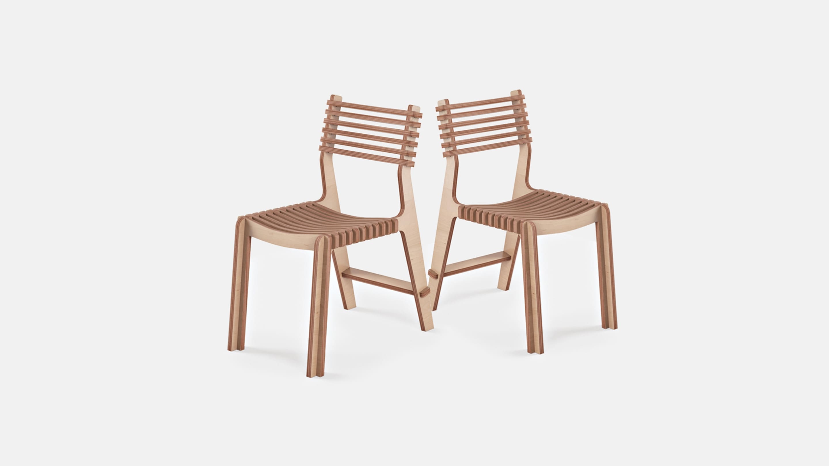
I found this chair called the Valovi chair on OpenDesk and loved the design.
I also found this side table a YouTuber had built using CNC-cut wood.
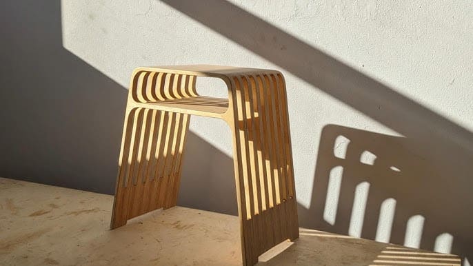
So I wanted to combine these two and make a fusion of them. What I decided to make was a school chair with a small chamber below the seat where books could be stored.
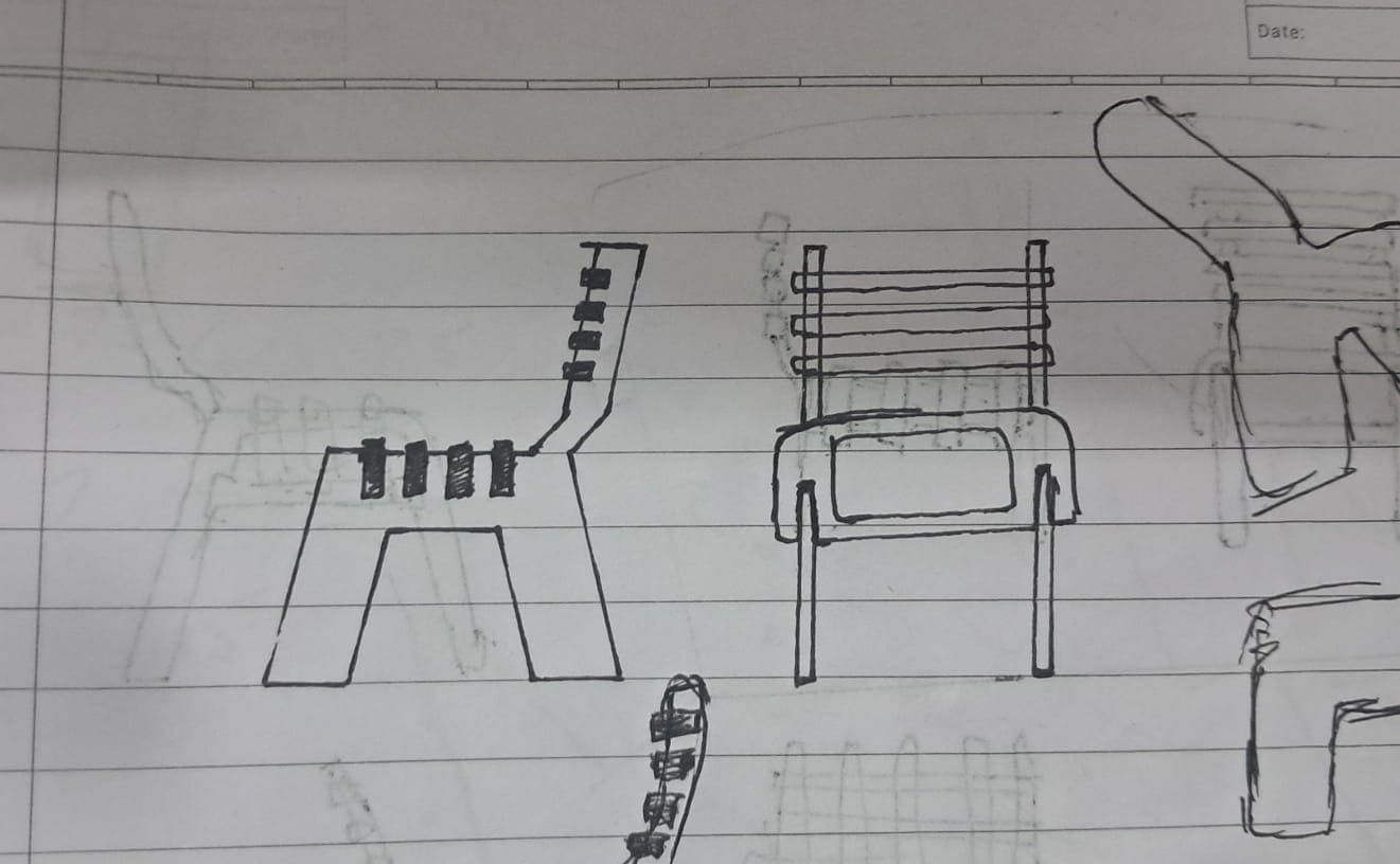
This was my first concept drawing.
With complete optimism I went into Fusion. The goal was to make it as close to my concept as possible while keeping it parametric.
Fusion
I started by designing sketches for three main parts: the blocks you lean on, the blocks you sit on, and the side faces.
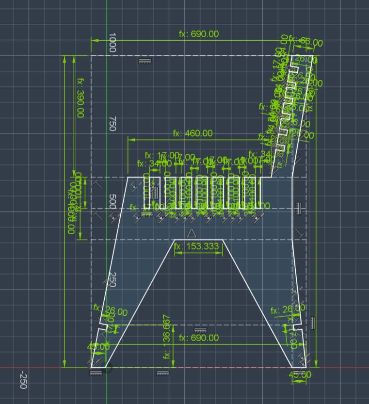
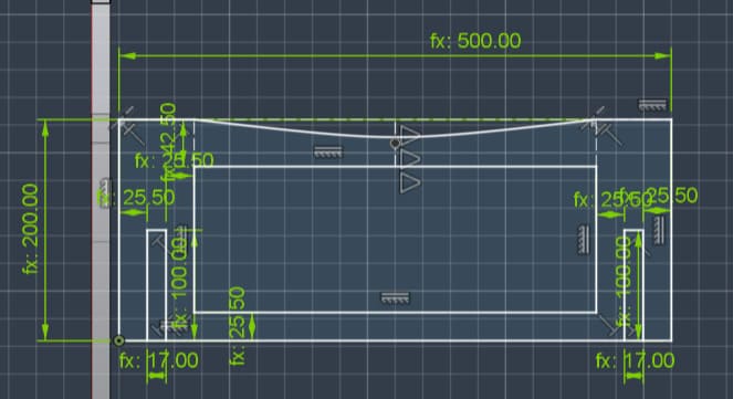
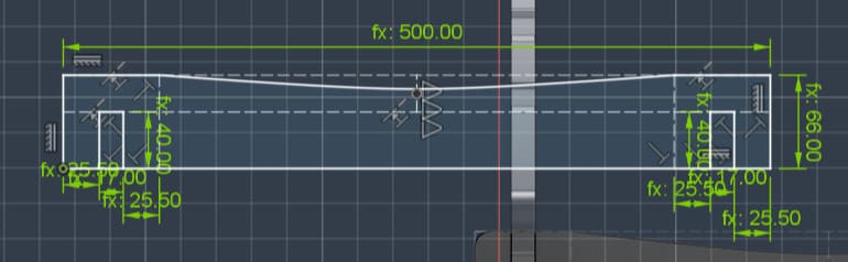
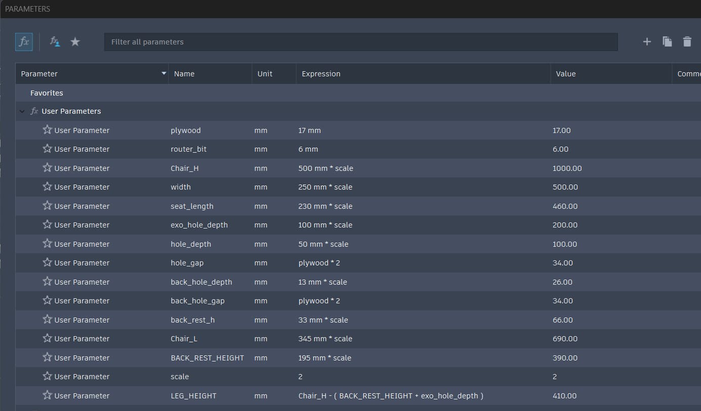
I then extruded all these parts. For the slots, the thickness of the plywood had to be accounted for. While designing I initially considered it to be 12mm, but I later increased it to fit 18mm plywood since it is furniture that needs to support weight. This was easy to change due to the parametric nature of the design.
Next I began making the model parametric. I went a little crazy with the number of variables though. Initially I wanted it to be just height, width, length of the chair, and plywood thickness, but it became much more complicated. In hindsight I over-engineered it, but technically it is still parametric.
An optimistic way to look at it is that I made the chair far more customizable than originally intended.
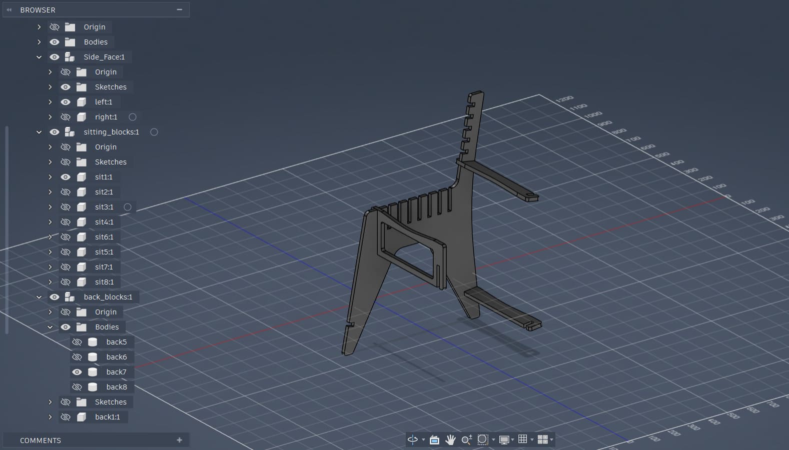
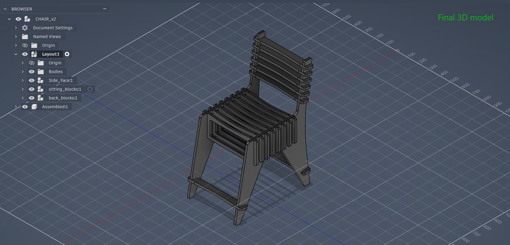
Here is the final 3D model.
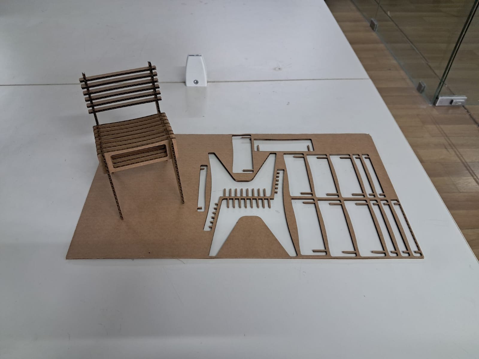
Laser Cutting Cardboard
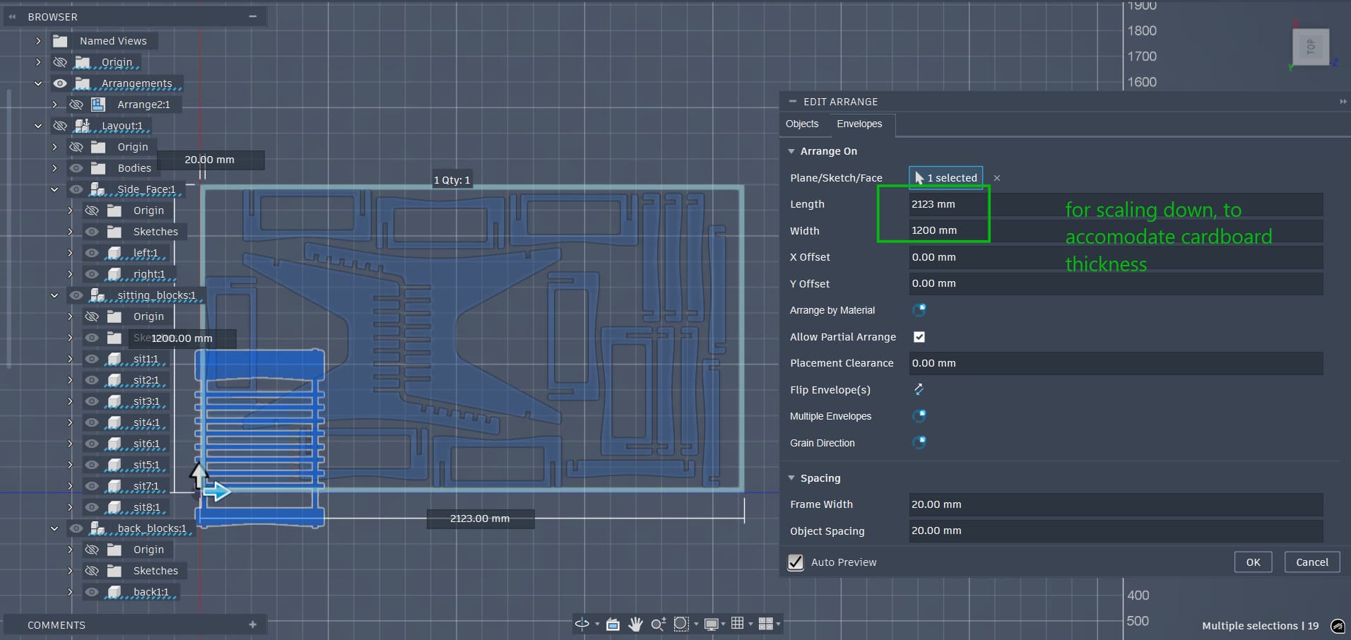
Before cutting the plywood we were tasked with making a model using cardboard first. Even though my design was parametric and the thickness and size could simply be changed, I chose to scale the entire model down.
When designing the model I assumed the plywood thickness to be about 12mm. From previous weeks I knew the available cardboard thickness was around 3mm and we needed to account for a 0.3mm kerf. For additional tightness I wanted to scale 12mm down to about 2.6mm.
This gave a scale factor of 4.61. To make things easier, I measured the cardboard sheet I was going to use and multiplied it by the factor, then arranged the components accordingly in Fusion.
The cardboard size was 260mm × 460mm. The maximum bed size of the Trotec Speedy 100 is 300mm × 600mm, so I cut a smaller piece. After scaling by the factor of 4.61 I obtained 1200mm × 2123.077mm and arranged all the components accordingly.
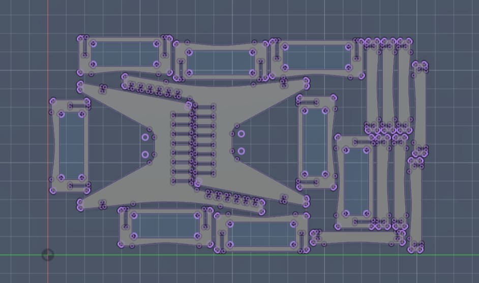
I then projected the surfaces to a sketch and exported a DXF.
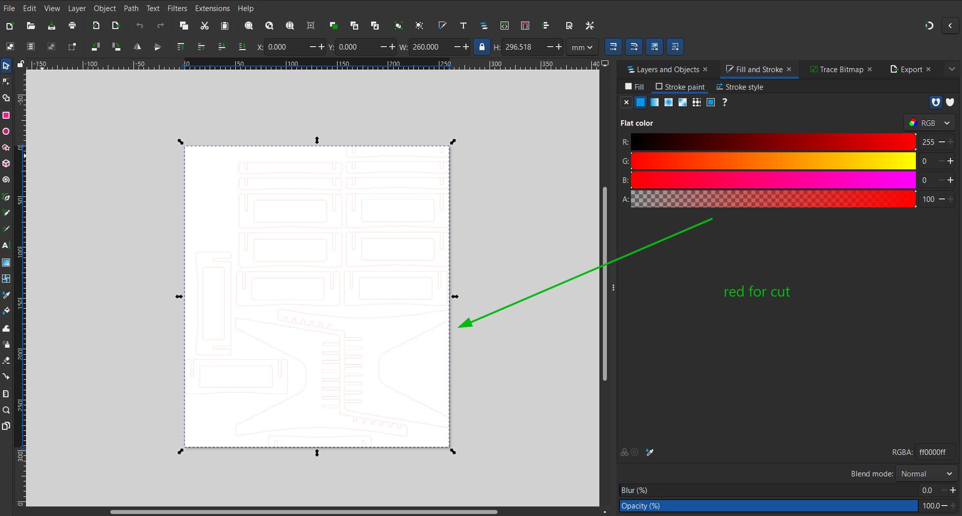
The DXF was opened in Inkscape and the outline fill was changed to red for the Trotec JobControl software, where the colour red is set for a perfect cut.
I let JobControl and the Trotec Speedy 100 do the rest and obtained my cardboard prototype.
Preparing for the Cut
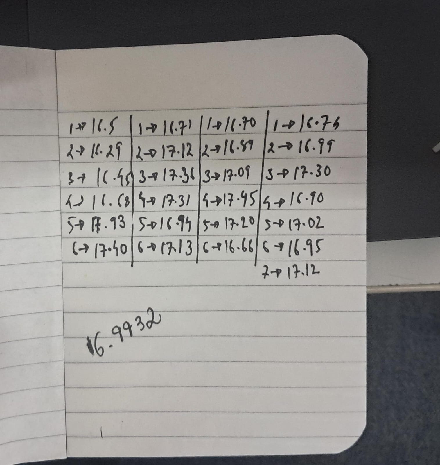
To prepare for the cut I needed the actual thickness of the plywood I would be using. I chose a piece and measured its thickness around all sides, then averaged about 25 measurements and obtained 16.9932mm. I rounded this to 17mm as my plywood thickness.
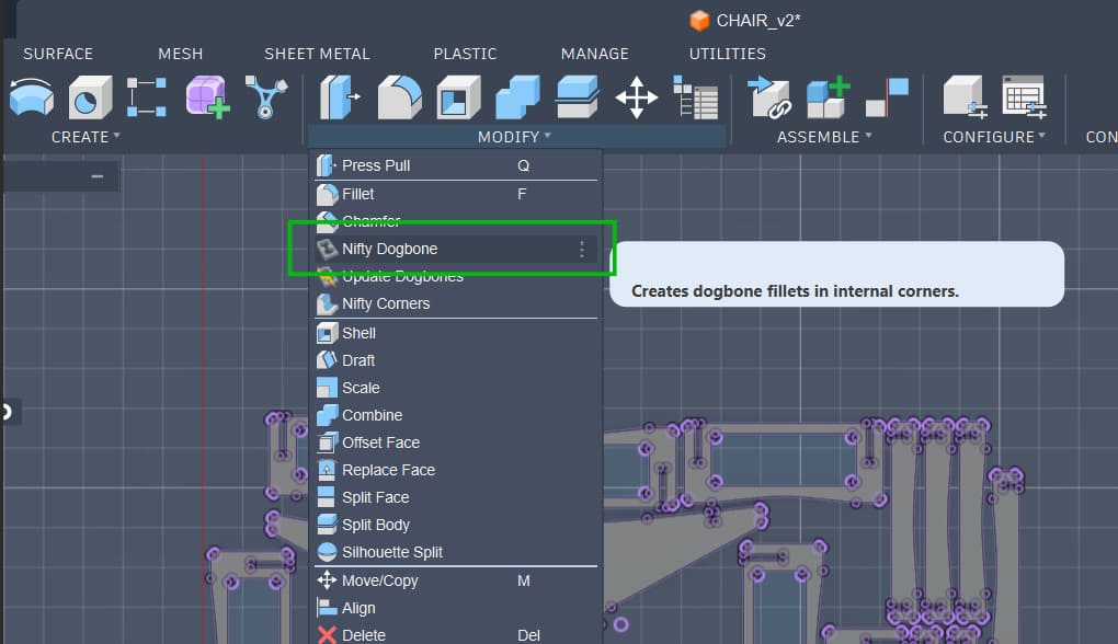
With the correct thickness I updated the parametric value for plywood thickness, arranged the parts, and exported the DXF. I also used the Nifty Dogbone tool to add dogbones and arranged the components on an 8-foot by 4-foot workspace to match the plywood sheet size.
Dogbones are added because a circular drill cannot make perfect 90-degree internal corners. We cut slightly extra material so the slots can properly accommodate the parts.
CAM Software – VCarve
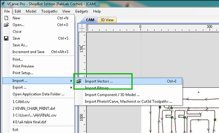
The workflow in our lab for generating the G-code uses VCarve. A new file is created and the stock thickness and workspace size are set to match the 8-foot by 4-foot plywood sheet.
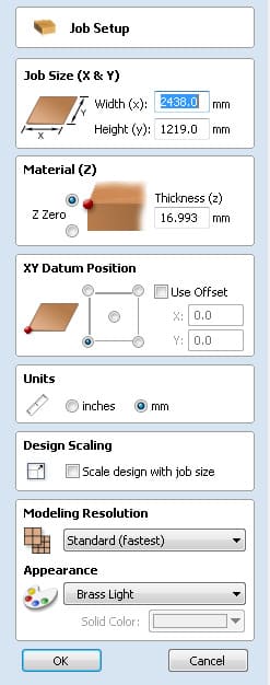
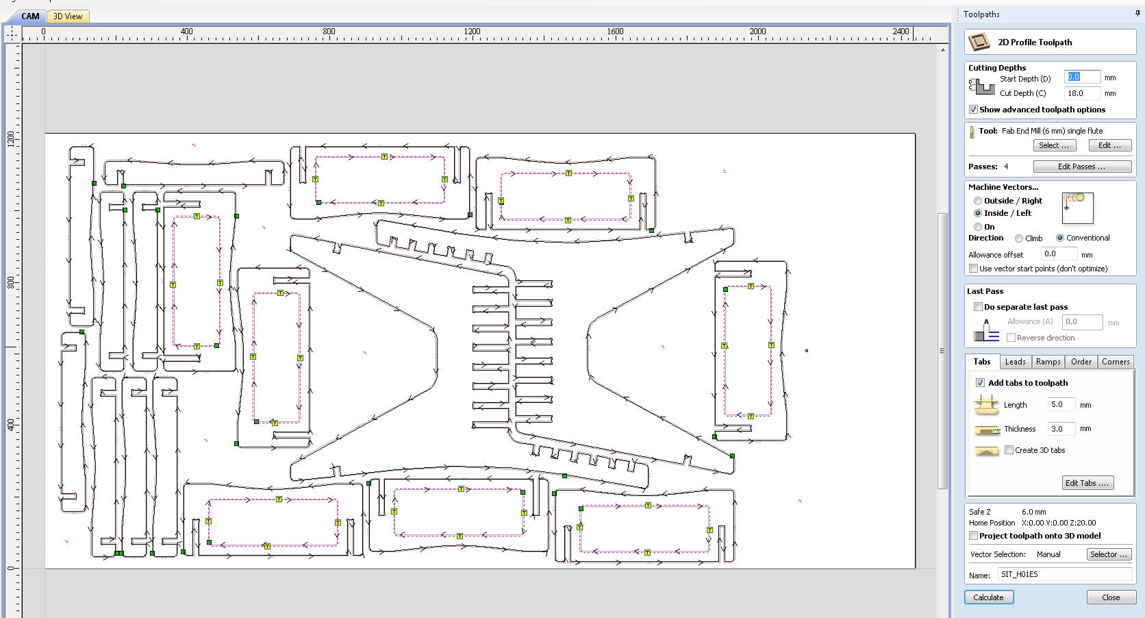
The DXF file is then imported and arranged on the canvas.
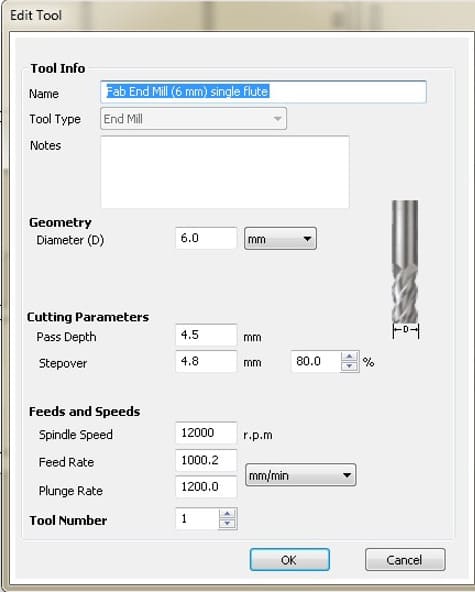
Before starting the large cut we first drill holes into the workpiece to secure it to the sacrificial layer. To mark the drill positions we used the circle vector tool in the CAM software. The end mill used was a 6mm diameter bit.
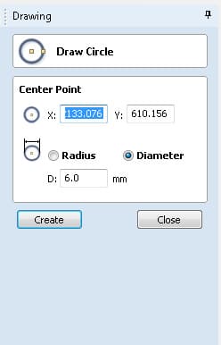
The drill holes were placed around the workpiece to ensure it remains flat on the workbench, as wood can warp and is not perfectly uniform.
Holding shift and selecting all the drill holes allows us to set them as a drill toolpath.
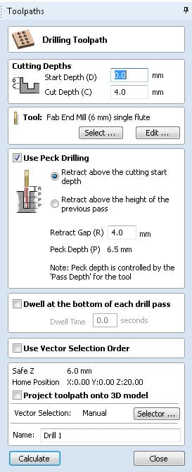
This toolpath goes only 4mm deep into the 18mm plywood, just enough to mark the holes for screws. This becomes the first toolpath.
Next we set the internal toolpaths. These are always cut before the outer profiles for safety. If an outer piece were cut first and the tabs failed, the loose piece could move during machining.
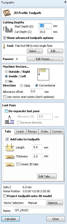
Even though the plywood thickness is 17mm, we cut slightly deeper to ensure a clean cut. The sacrificial layer below the workpiece protects the machine bed.
Tabs are also added to prevent pieces from coming loose during cutting.
Finally, the outside profiles are set.
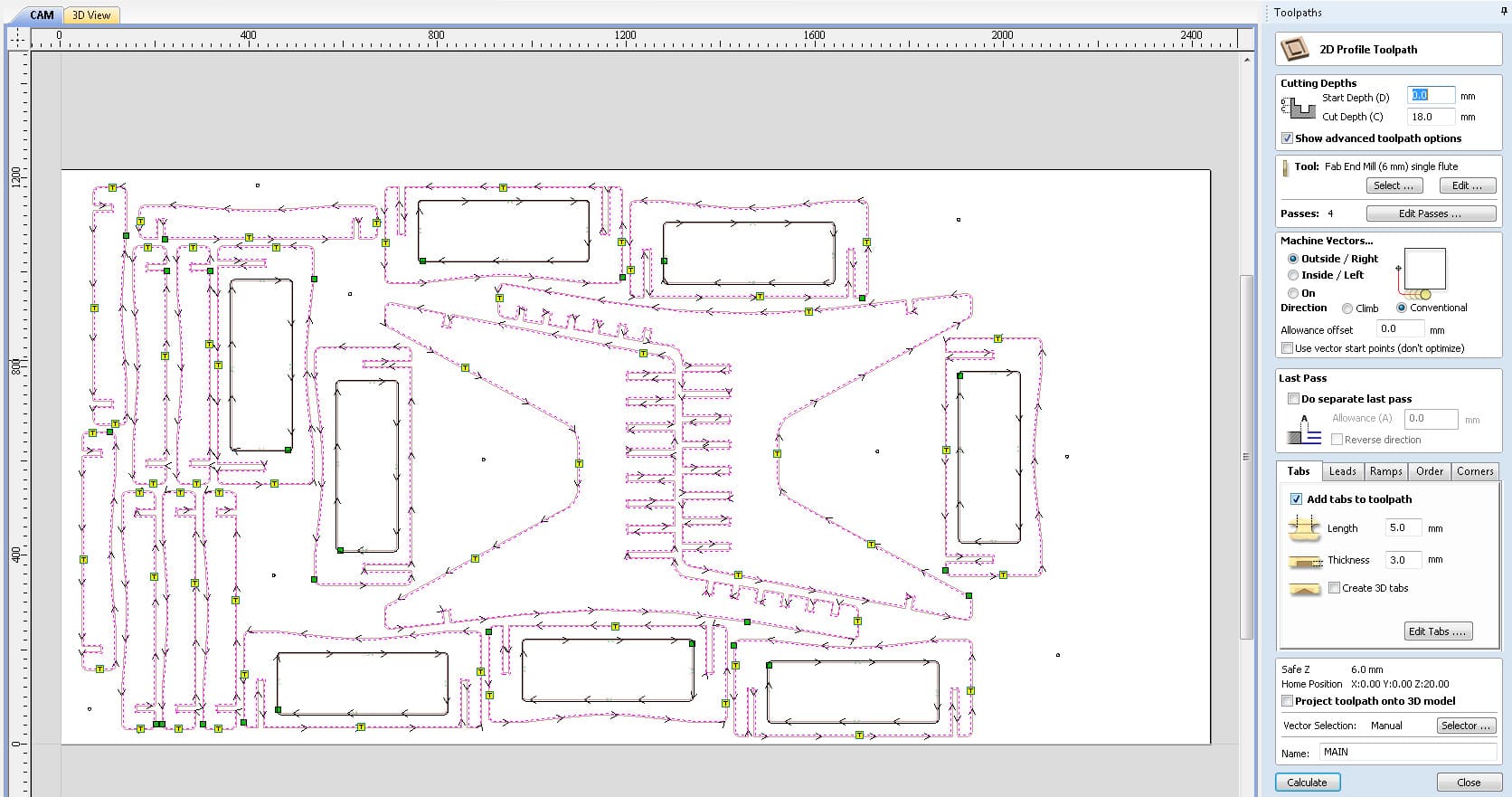
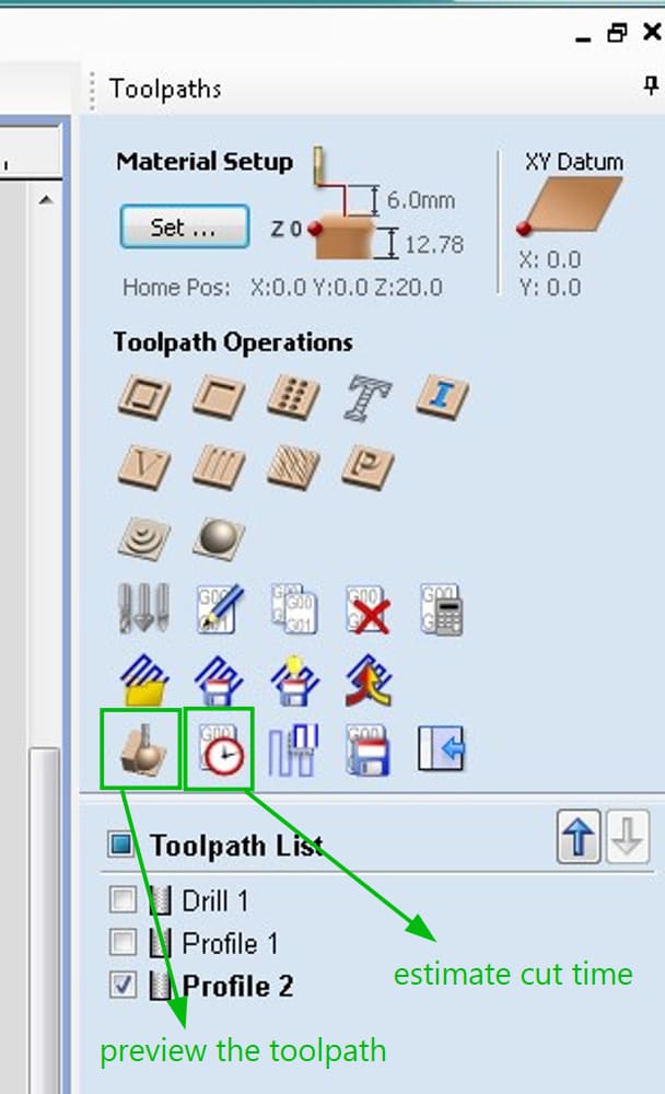
I now had three toolpaths: drilling, inside cuts, and outside cuts. The drill toolpath is exported first as an SBP file for the ShopBot so the workpiece can be secured. The inside and outside toolpaths are exported together since they both use the same 6mm bit.
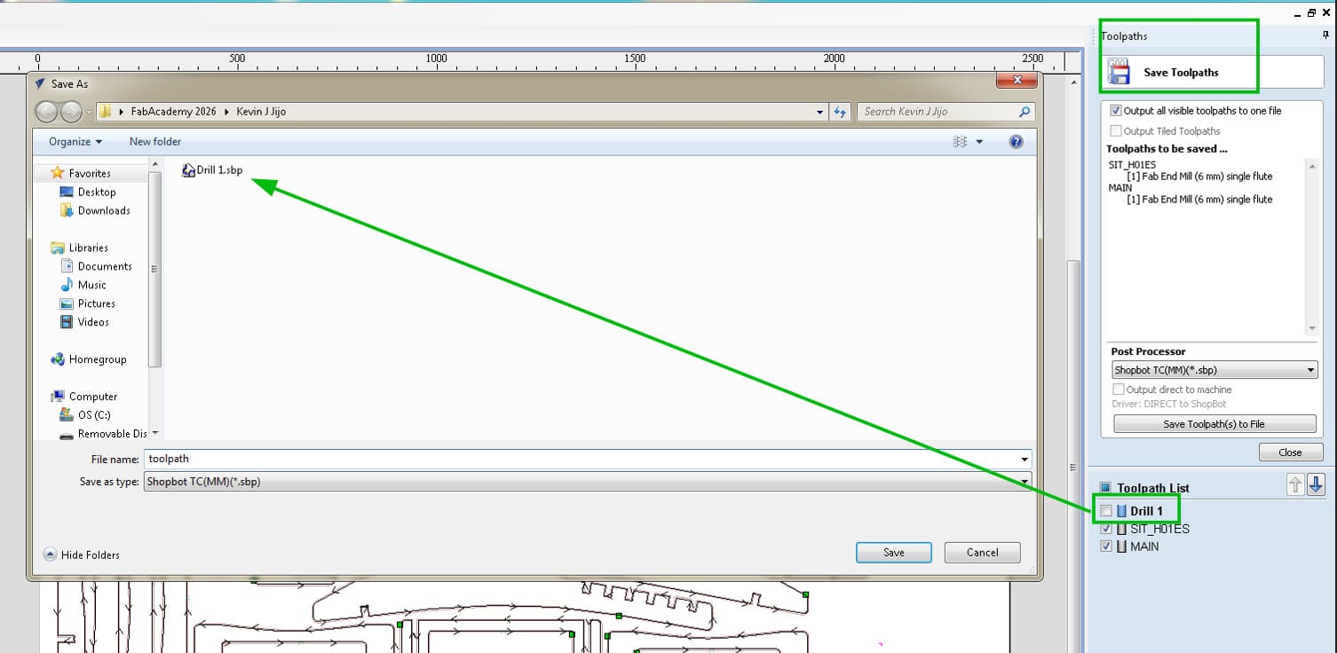
The simulation of the tool moving along the toolpaths can be viewed using the preview toolpath option.
ShopBot Cutting
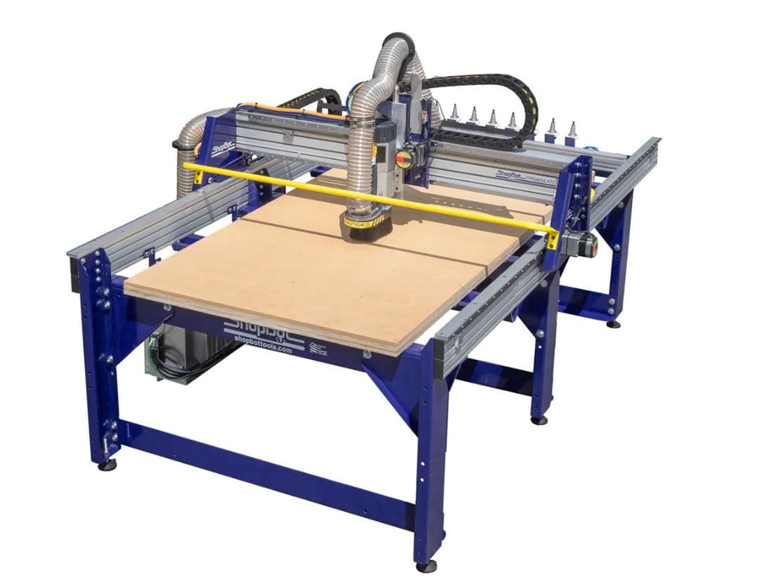
ShopBot PRSAlpha 96
In the ShopBot software we first home the X and Y axes, then set the workpiece origin, and finally home the Z axis. We run the drill toolpath first and use those points to secure the workpiece to the sacrificial layer with screws.
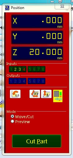
We then click “Cut Part”, choose the SBP file, disengage the spindle when prompted, start it using the green switch, and confirm to begin the cut.
Post Processing
After cutting, the parts are removed by breaking the tabs using a chisel and mallet. The excess wood is removed and the work surface is cleaned using a vacuum cleaner.
Post-processing begins by removing the remaining tab material.
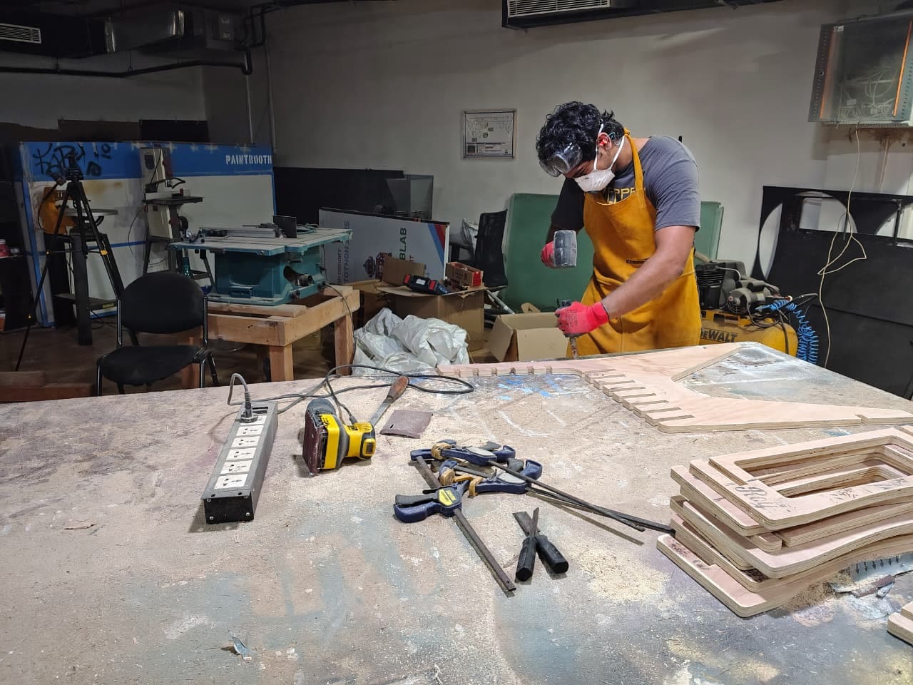
The surfaces can be sanded using a palm sander to remove the burn marks left on the plywood and smooth rough edges.
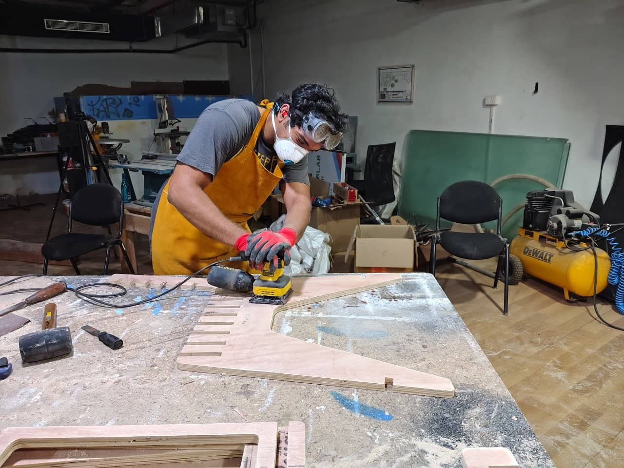
A file can then be used to clean up rough areas within slots where the sander cannot reach.
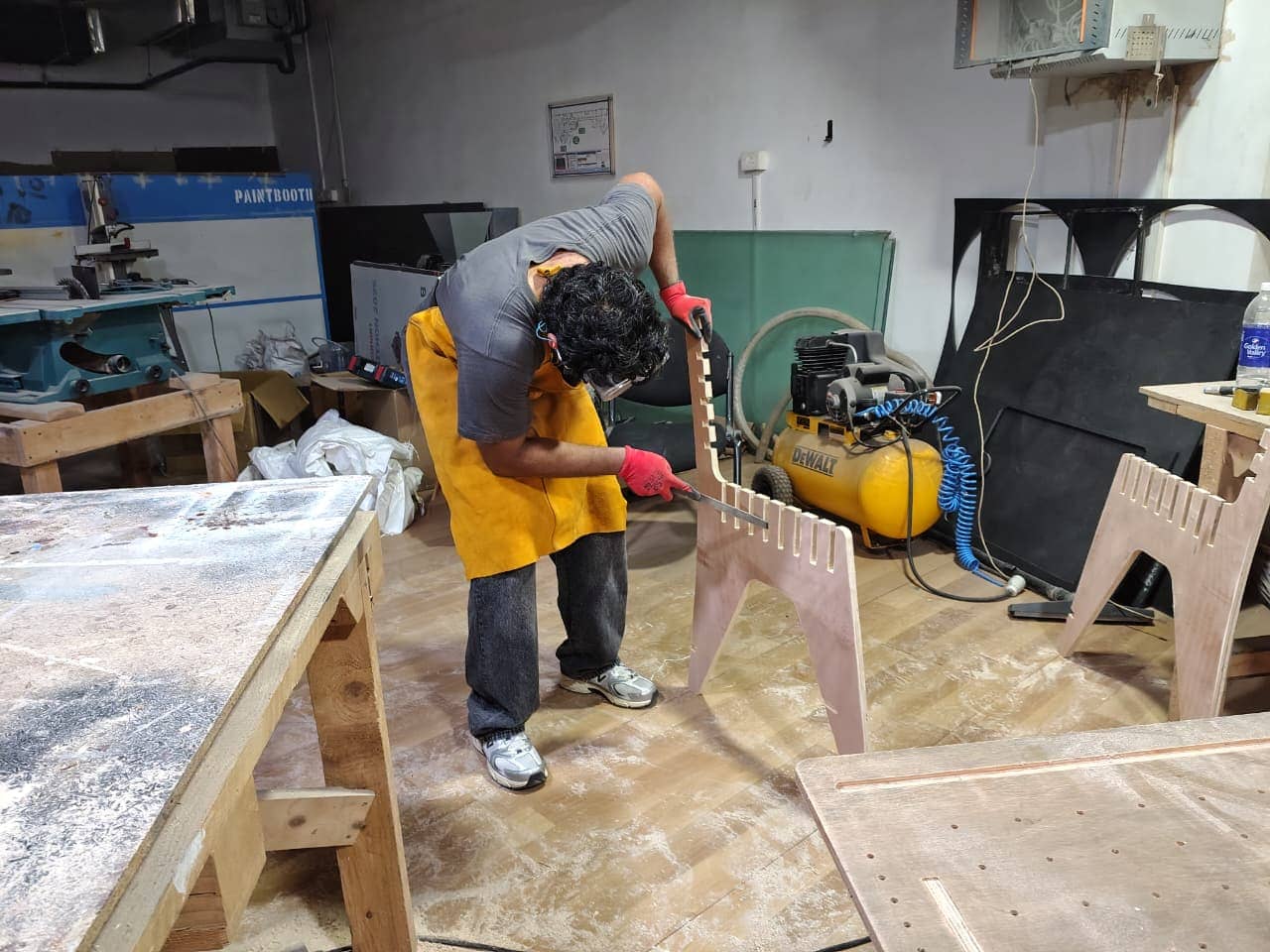
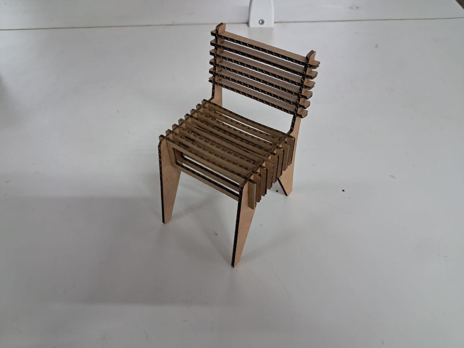
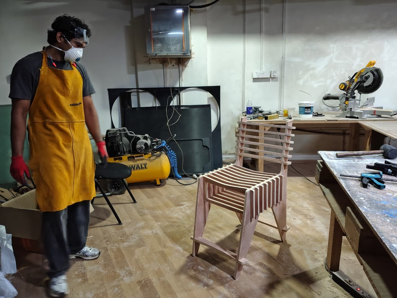
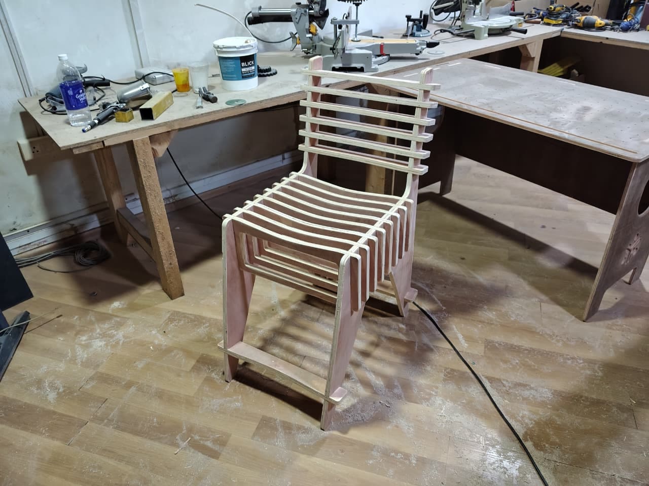
Finally, all parts are assembled using a mallet to secure the joints tightly, and the chair is complete.
The chair ended up slightly higher than planned, so I decided to convert it from a school chair to a bar stool. Quite the unexpected jump, but choices had to be made.
The Final Product
Caught me admiring my chair here.
Approved by Saheen.
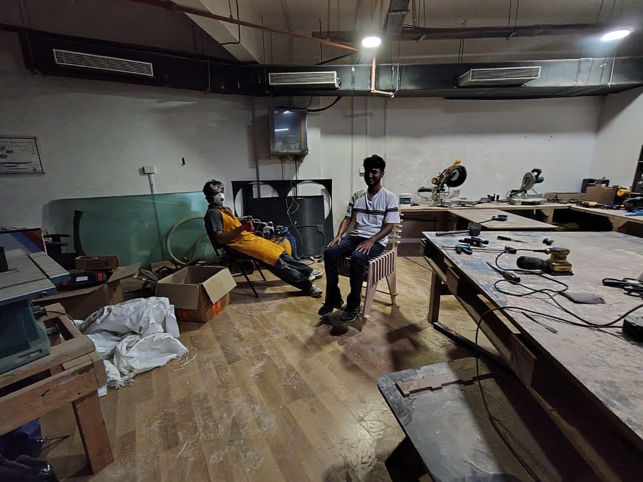
The chair in all its glory.
Key Takeaways
Focused too much on design and didn’t give ergonomics the attention it needed. Tried to make it look as good as possible without considering comfort and usability.
Was careless with the parametric design, altering a few measurements without proper prototyping. Didn’t take the necessary steps, which slightly affected the final product and the fit of the back supports with the frame.
Project Files
All project files can be downloaded here.