Project Development
- What tasks have been completed, and what tasks remain?
- Whats working? whats not?
- What questions need to be resolved?
- Planned what will happen when?
Project Development
Project Update: Vinyl Record Player Automation
This update covers progress on the enclosure, PCBs, mechanism, and firmware since the last documentation cycle. A few scope changes were made along the way due to time constraints, which are noted below alongside what was actually completed.
Gantt Chart and Scope Change
Below is the project Gantt chart showing the original planned timeline.
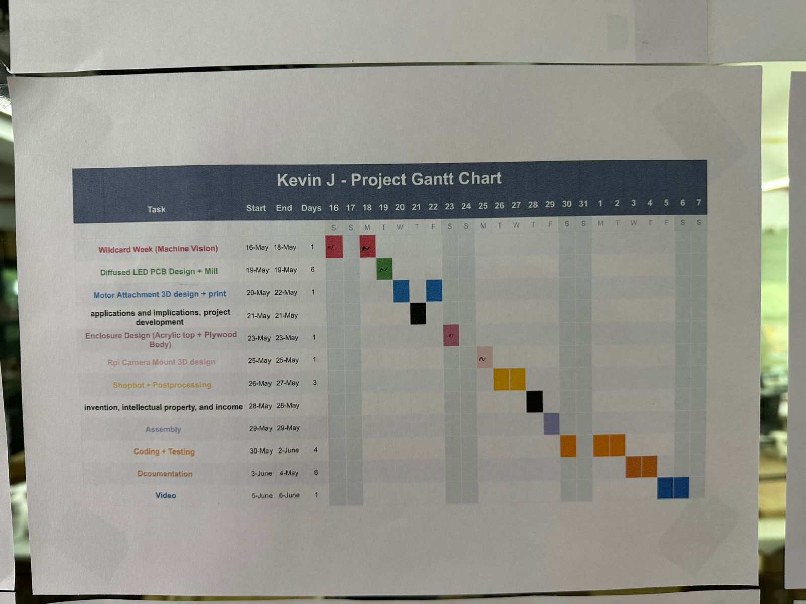
Due to lack of time, some parts of the original plan were cut. The physical stand meant to hold the Raspberry Pi camera was dropped in favor of a simpler approach: a web app now handles groove detection from an uploaded photo and sends the calculated groove distance to the XIAO over WiFi, instead of the camera doing live detection on the device itself.
Groove Detection and Camera Stand
Before the scope change, a few scripts for groove detection were written and tested, along with a stand designed to hold the Raspberry Pi camera and a diffused light setup for more consistent image capture.
Mechanism Simplification
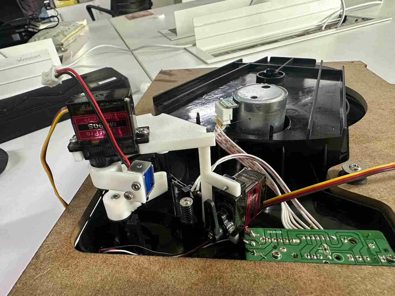
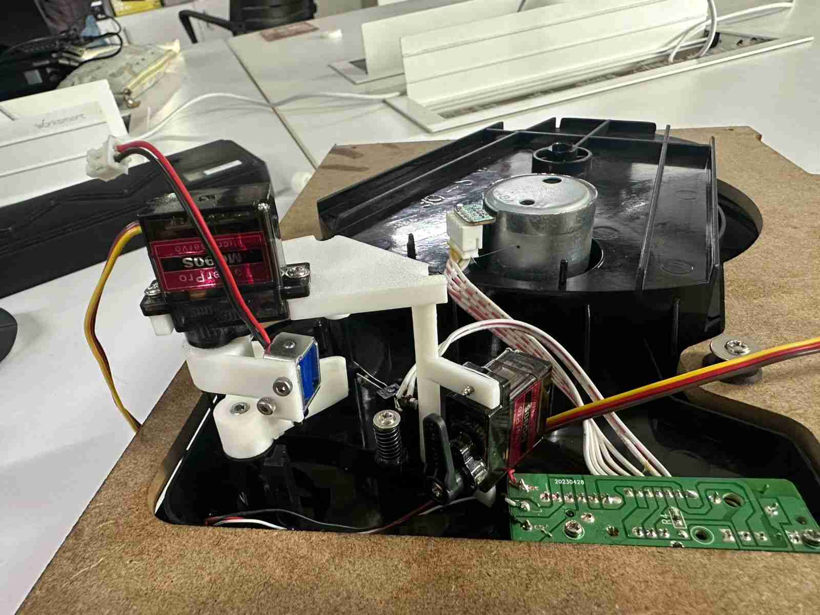
The original plan used a servo and a stepper motor together for tonearm positioning. To keep things simpler and more reliable, this was changed to use two servos instead. This mechanism has since been printed and tested.
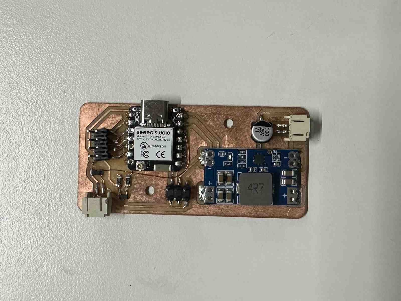
Main PCB
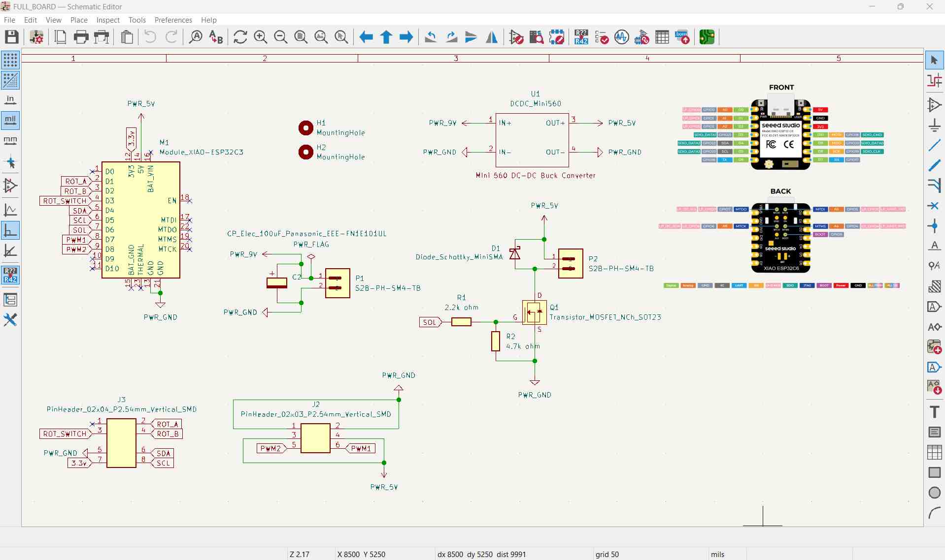
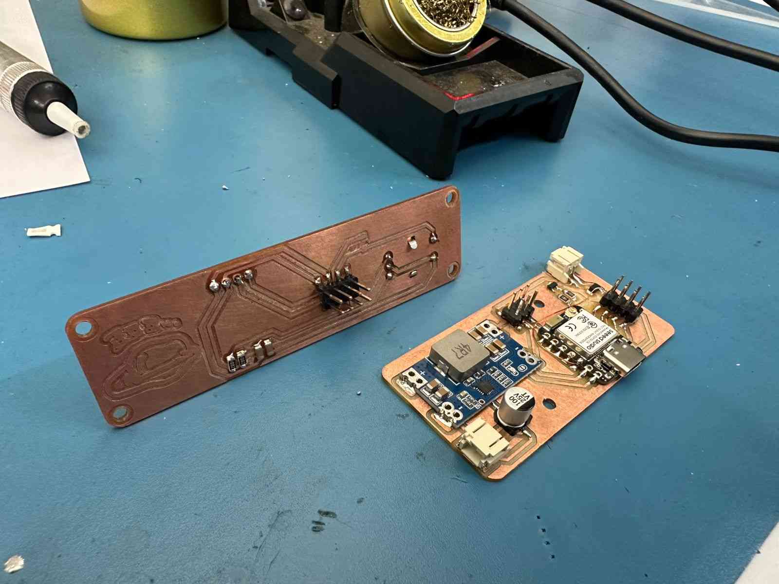
The schematic design for the main board was completed. Since the board sits enclosed within the box and doesn't need to be shaped around anything, it was kept as a simple square PCB.
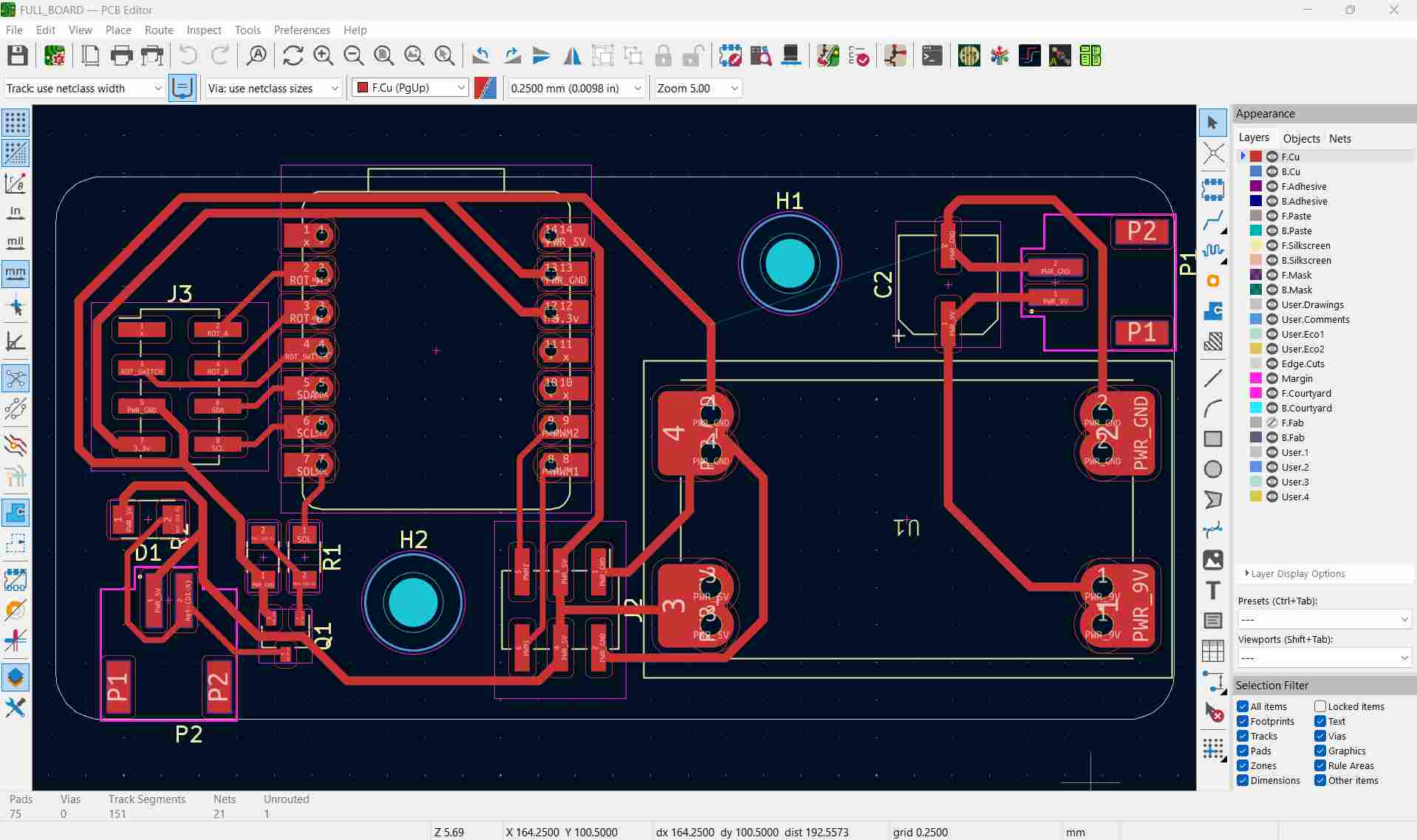
The board was milled.
And then soldered.
Breakout Board
A separate breakout board was designed for the input rotary encoder and the output OLED screen.
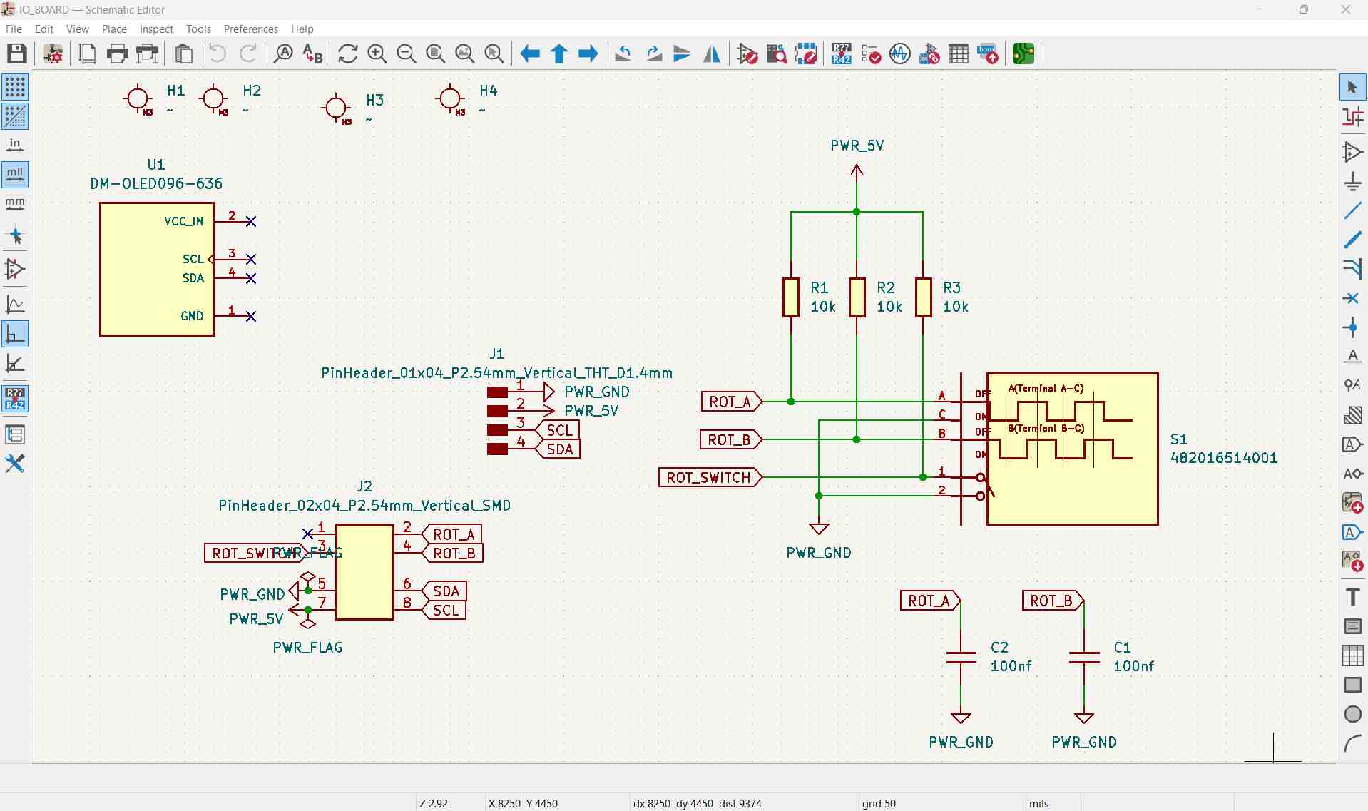
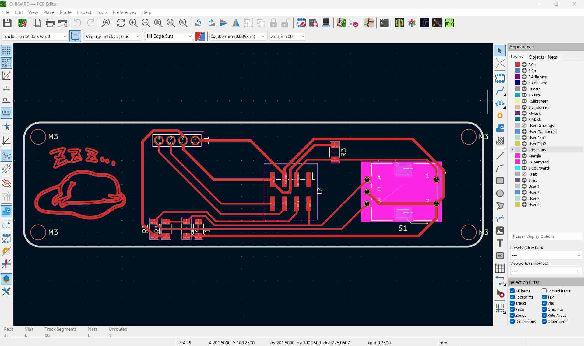
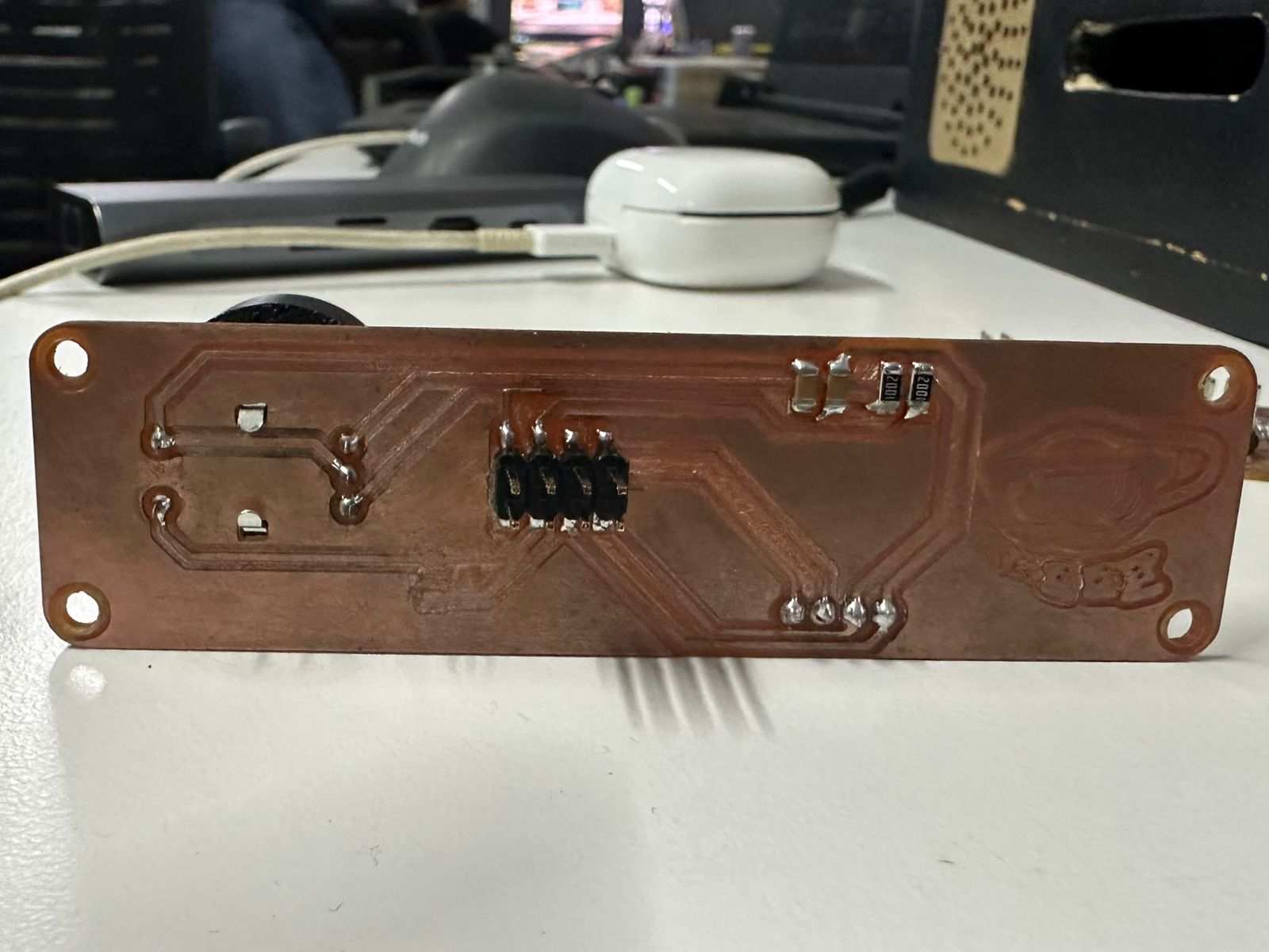
Both boards were tested with a multimeter for continuity before moving forward.
Enclosure and Display Mount Design
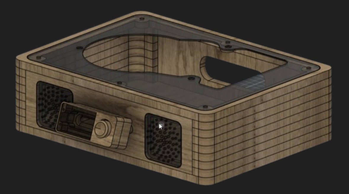
Work then moved to designing the enclosure and display mount. The enclosure was made from plywood slabs with an acrylic sheet top, while the display mount and the servo mechanism housing were both 3D printed.
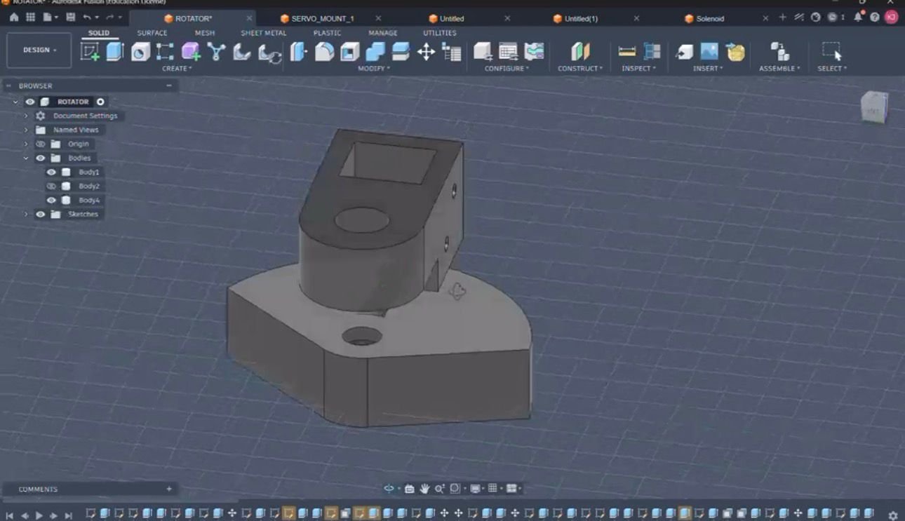
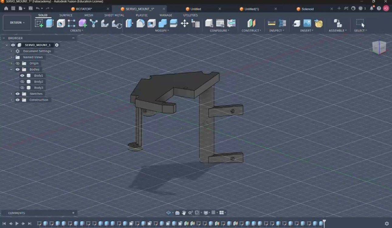
The enclosure design includes pockets on the top and front panels for the acrylic sheets, along with holes on the front and back for the I/O controls.
Milling the Enclosure
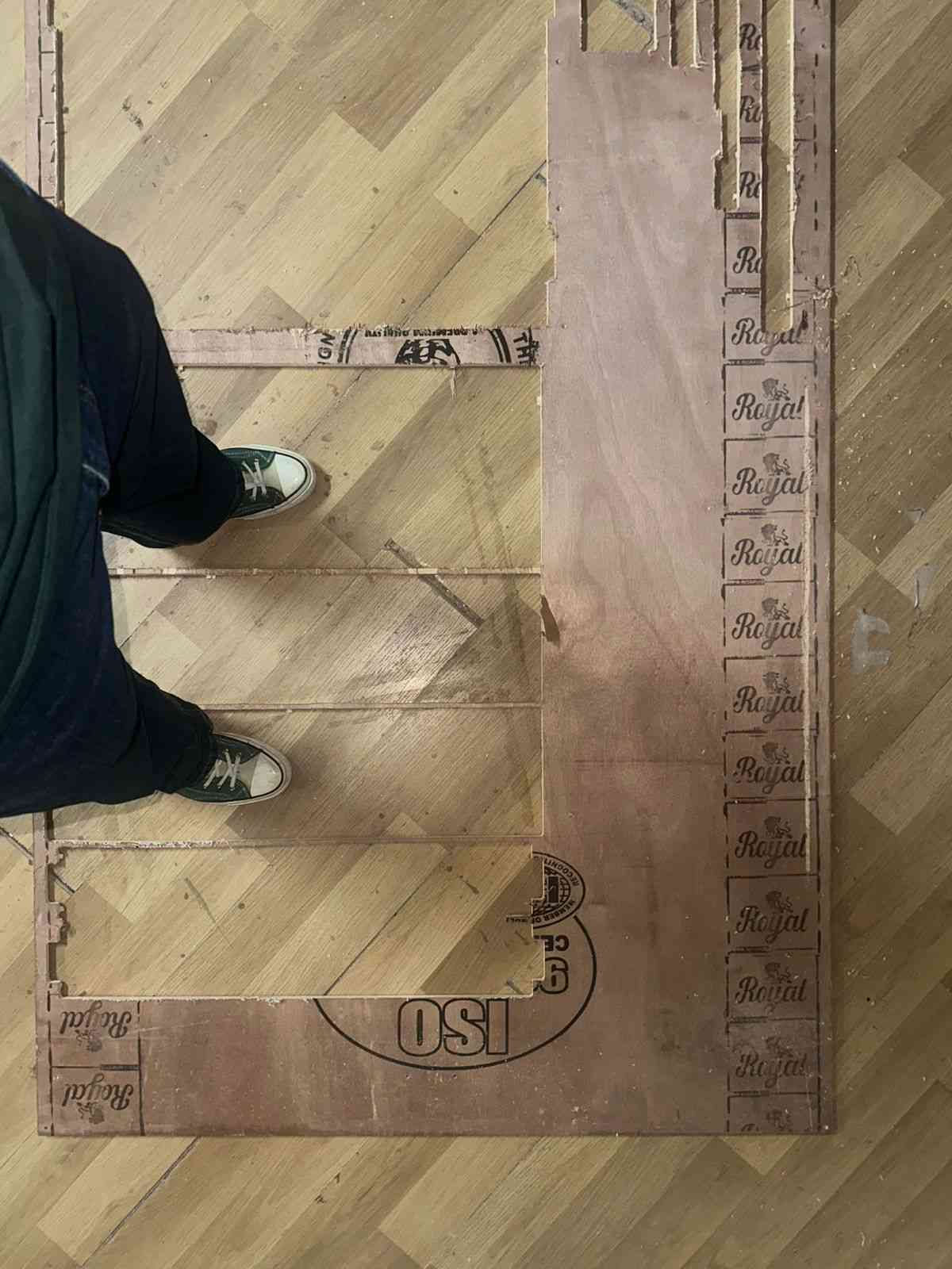
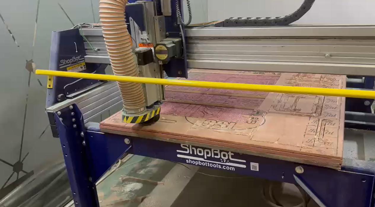
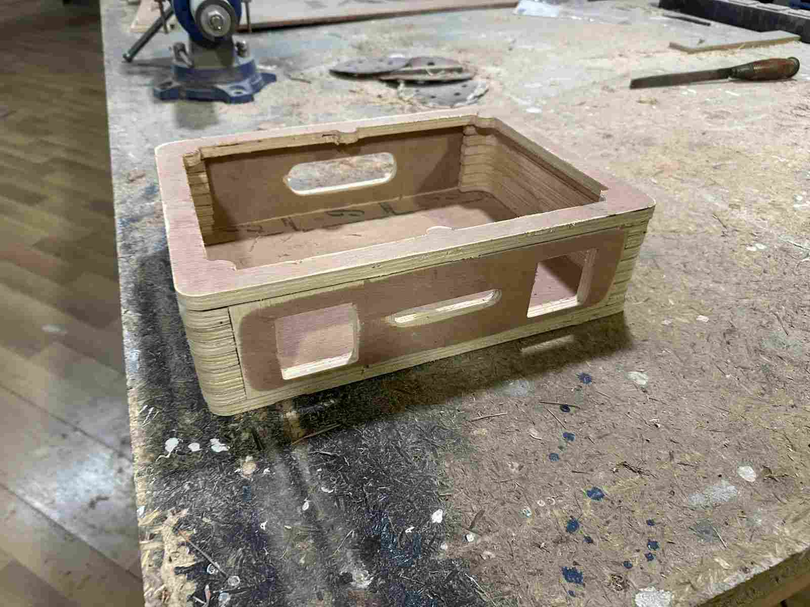
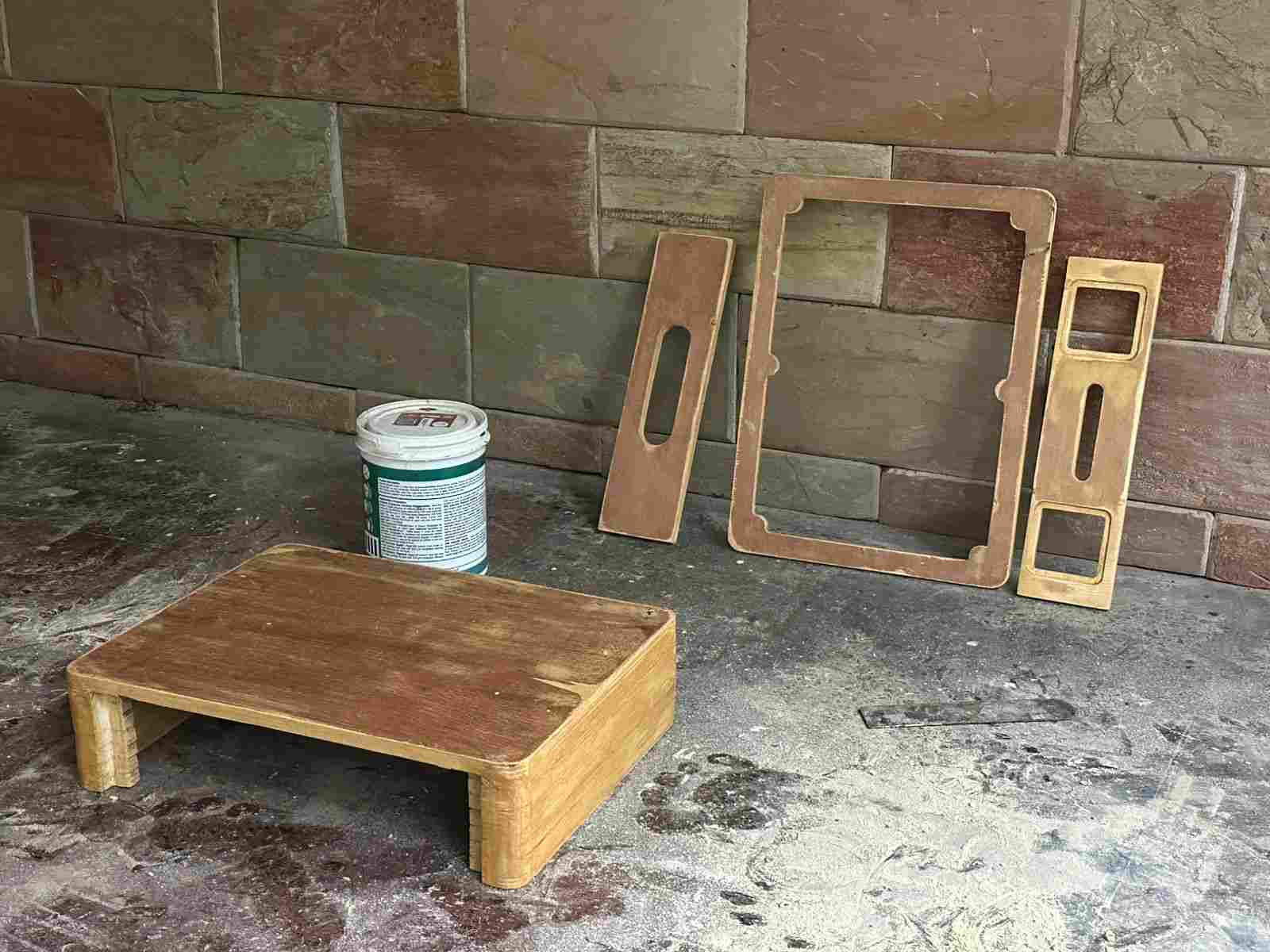
The enclosure panels were milled on the ShopBot. The plywood used for this is shown below.
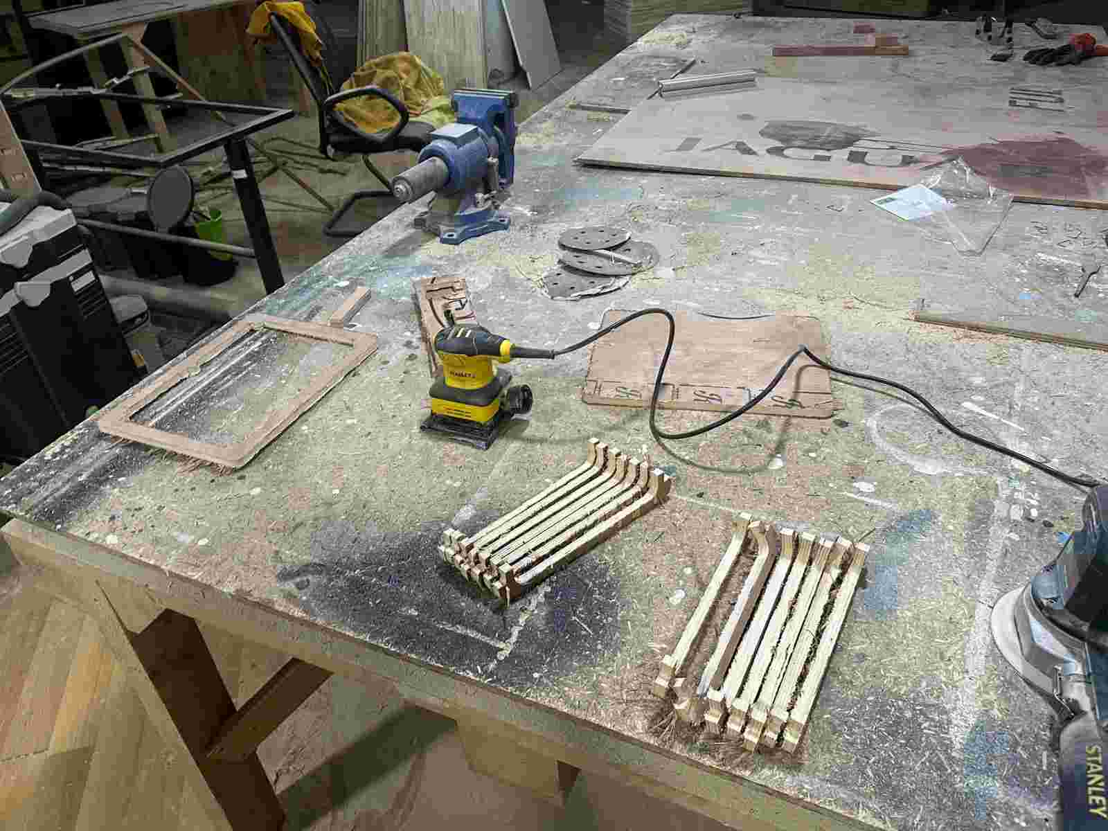
After milling, the plywood pieces were sanded and filed down for a better finish.
Here is how it looked once assembled.
Surface Finishing
The finishing process for the enclosure involved several stages: teak rosina powder, followed by rosina thinner mixed with chalk to fill any gaps, then a sanding sealer (diluted with thinner) to prep the surface for painting, and finally a matte black spray paint for the final coat.
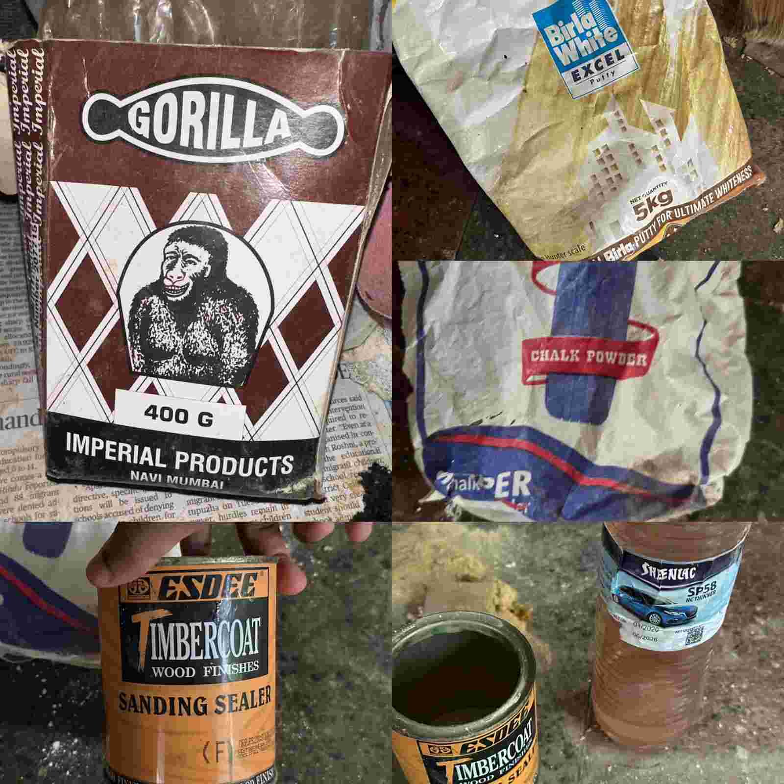
Product references used for this process:
- Gorila R-V (rosina/adhesive)
- Birla White Excel wall putty
- Superfine whiting chalk powder
- Esdee Timbercoat wood sanding sealer
- Sheenlac NC thinner
These were all used to give the enclosure a smoother finish after thorough sanding.
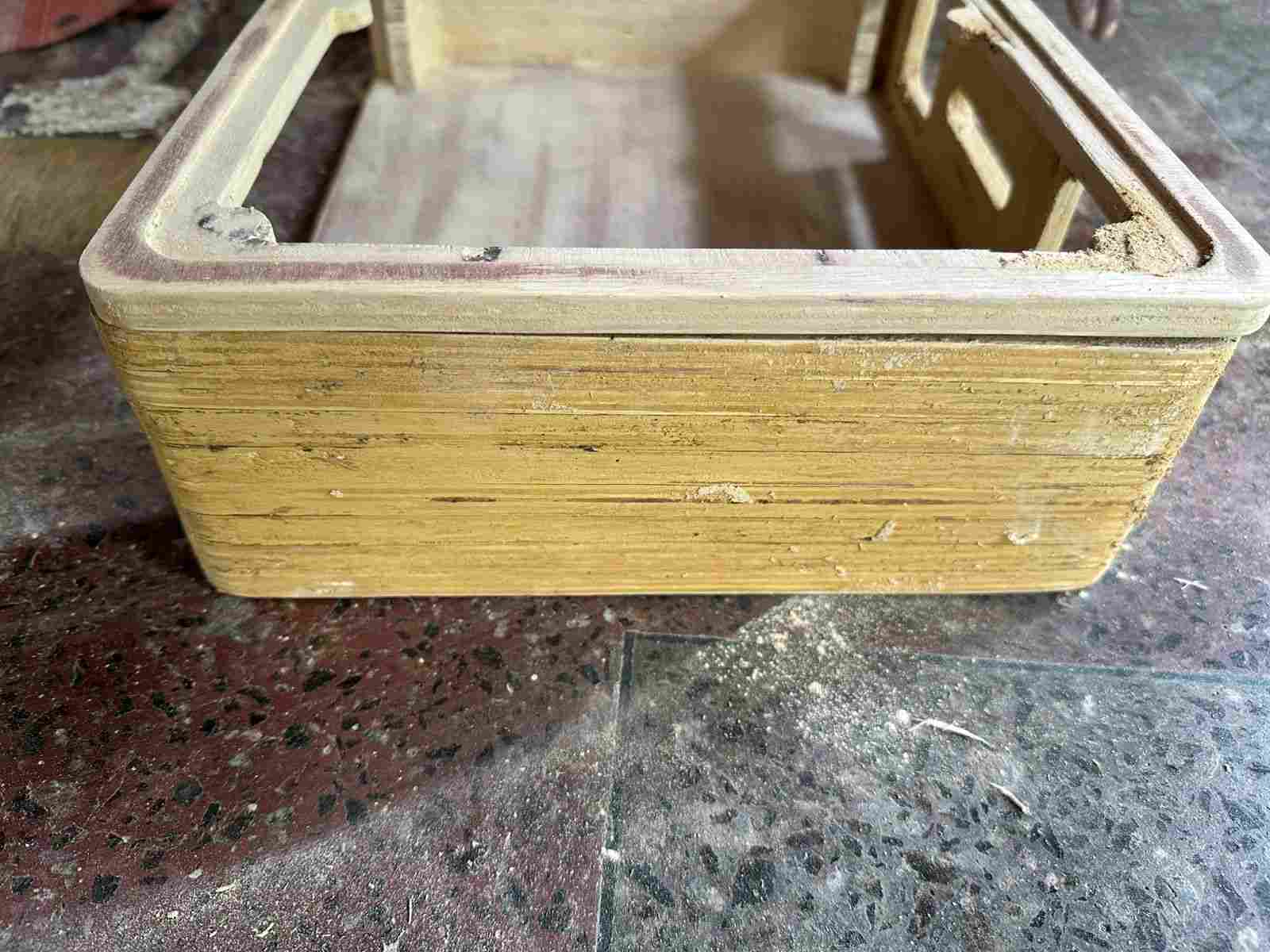
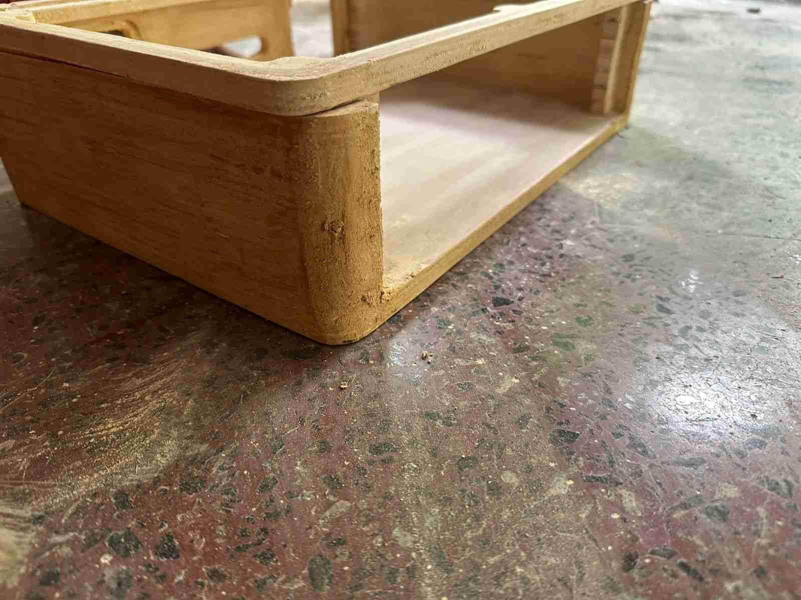
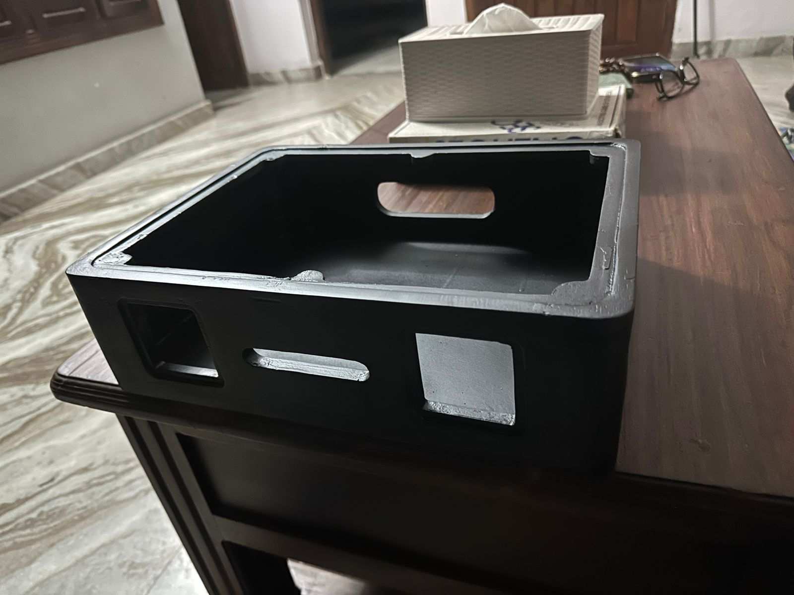
The enclosure was then spray painted.
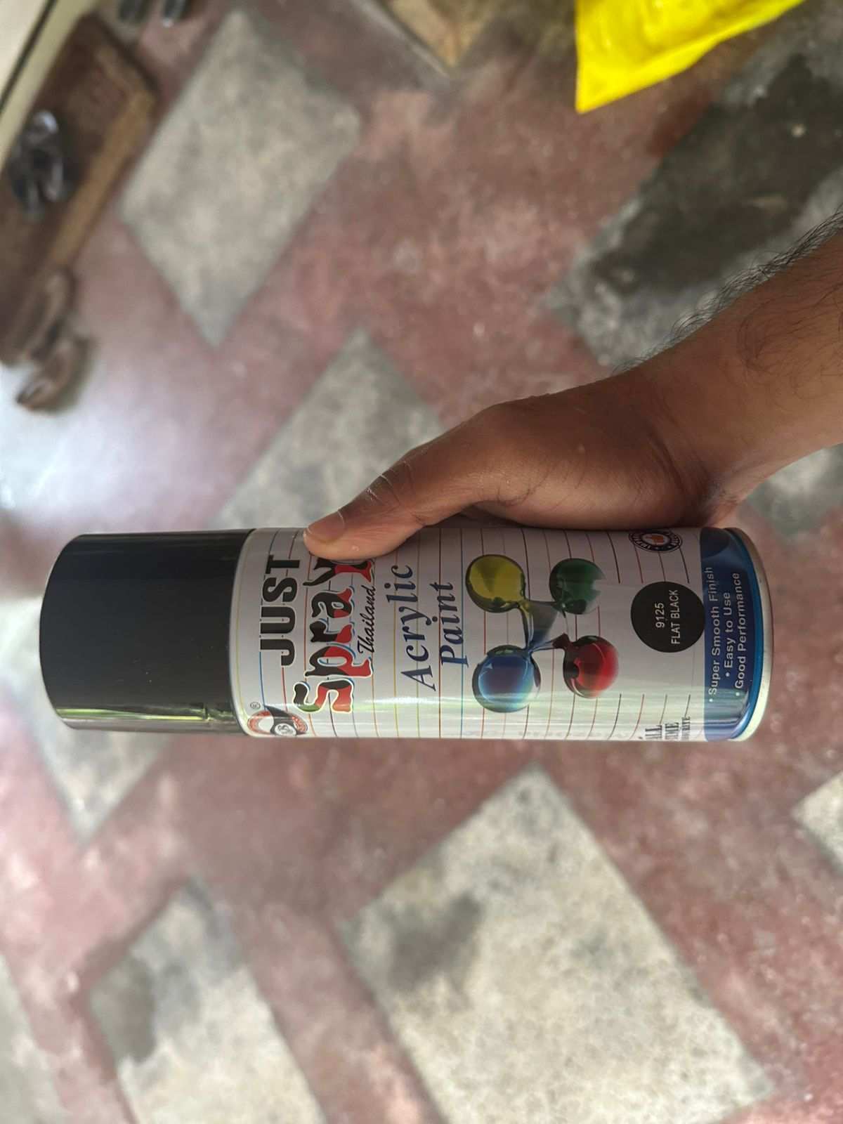
Paint reference: Just Spray Glossy Black
Acrylic Top and Speaker Mount
The acrylic speaker mount and the top mount were laser cut from a black glossy acrylic sheet, and the fit was tested against the enclosure.
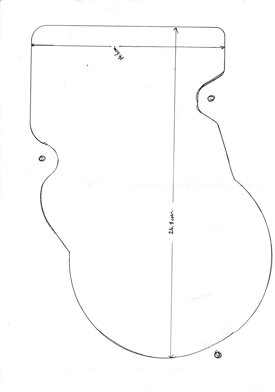
Before committing to the acrylic, the existing mechanism was test-fitted using a cardboard mockup to confirm dimensions.
The fit came out good.
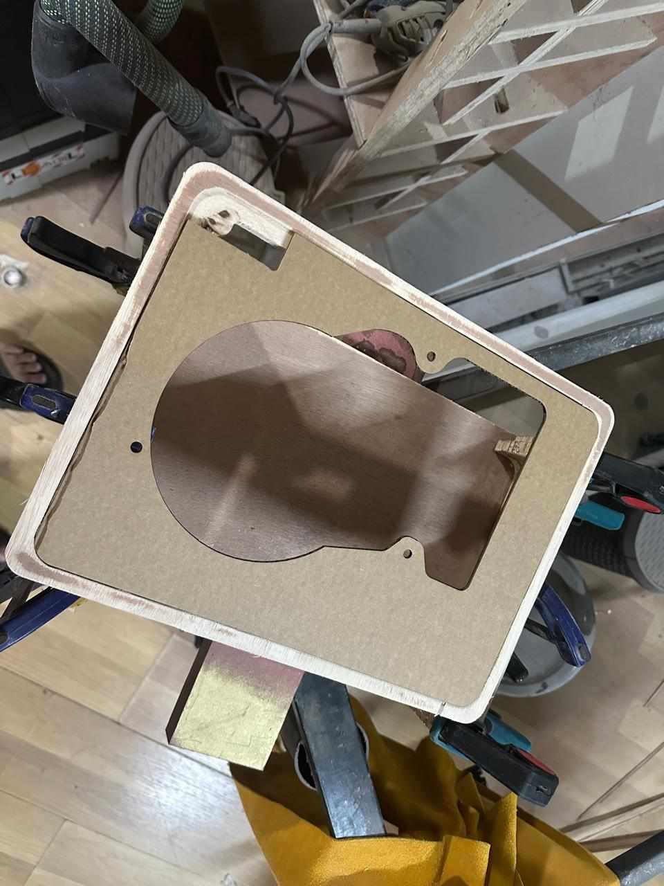
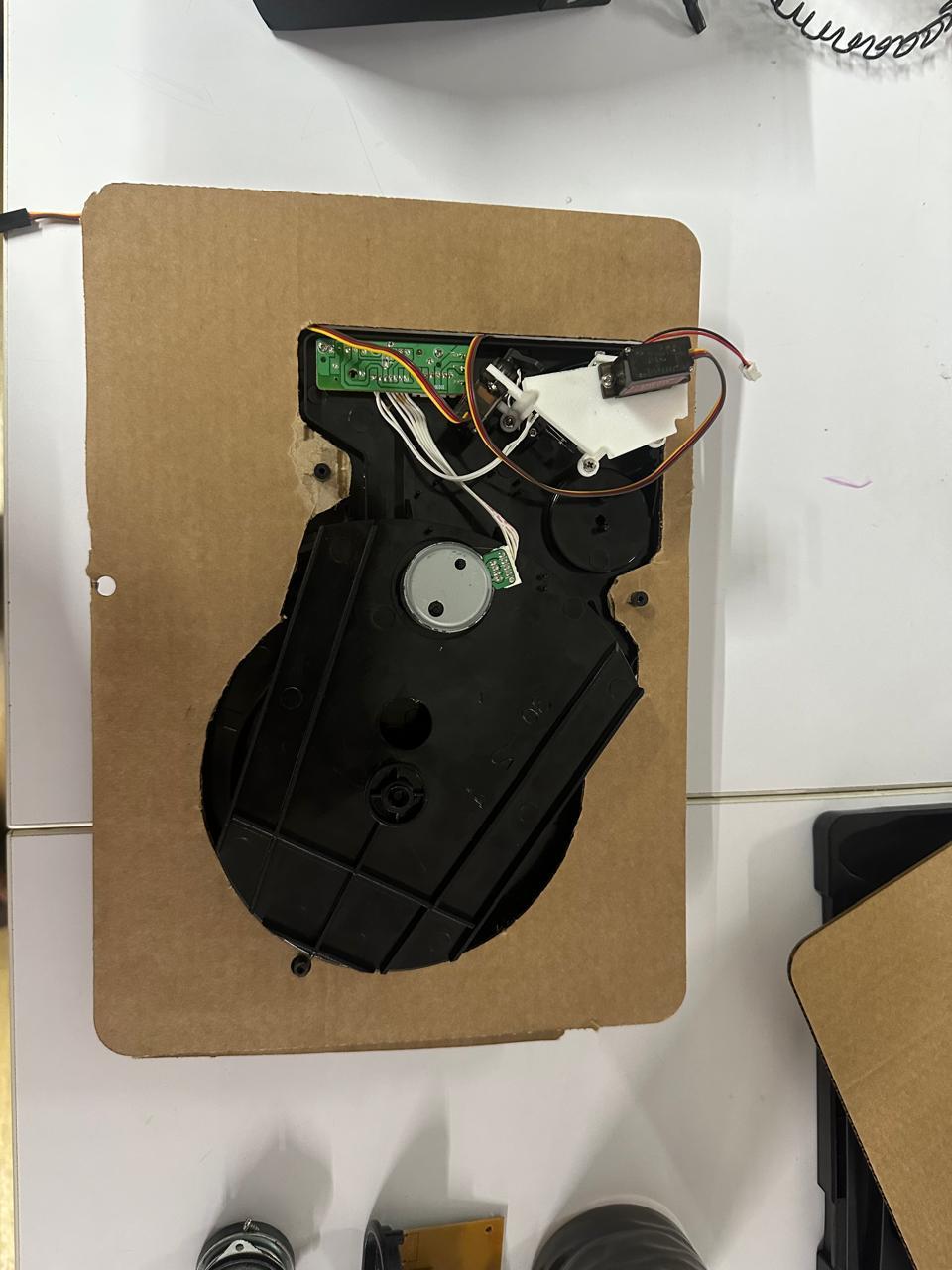
With the fit confirmed, the design moved forward to the actual acrylic cutting.
Mechanism Reprint and Assembly
The servo mechanism was reprinted, and the display mount was printed for the first time.
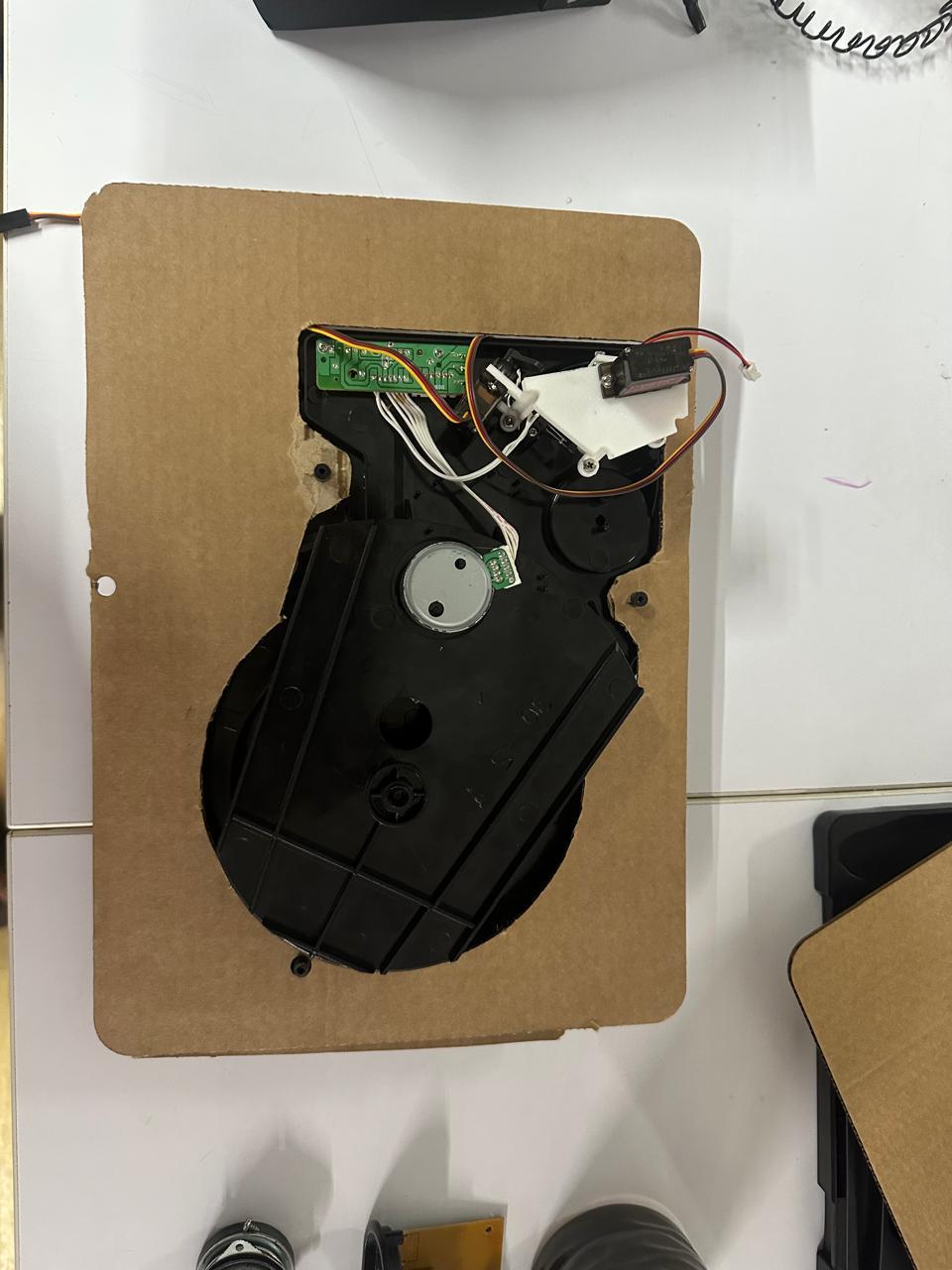
Both were printed in black to match the rest of the enclosure. The mechanism was tested again before final assembly.
The unit was then assembled, with the display module and speaker grill press-fitted into place. At this point, the full vinyl player was set up and assembled as a complete physical unit.
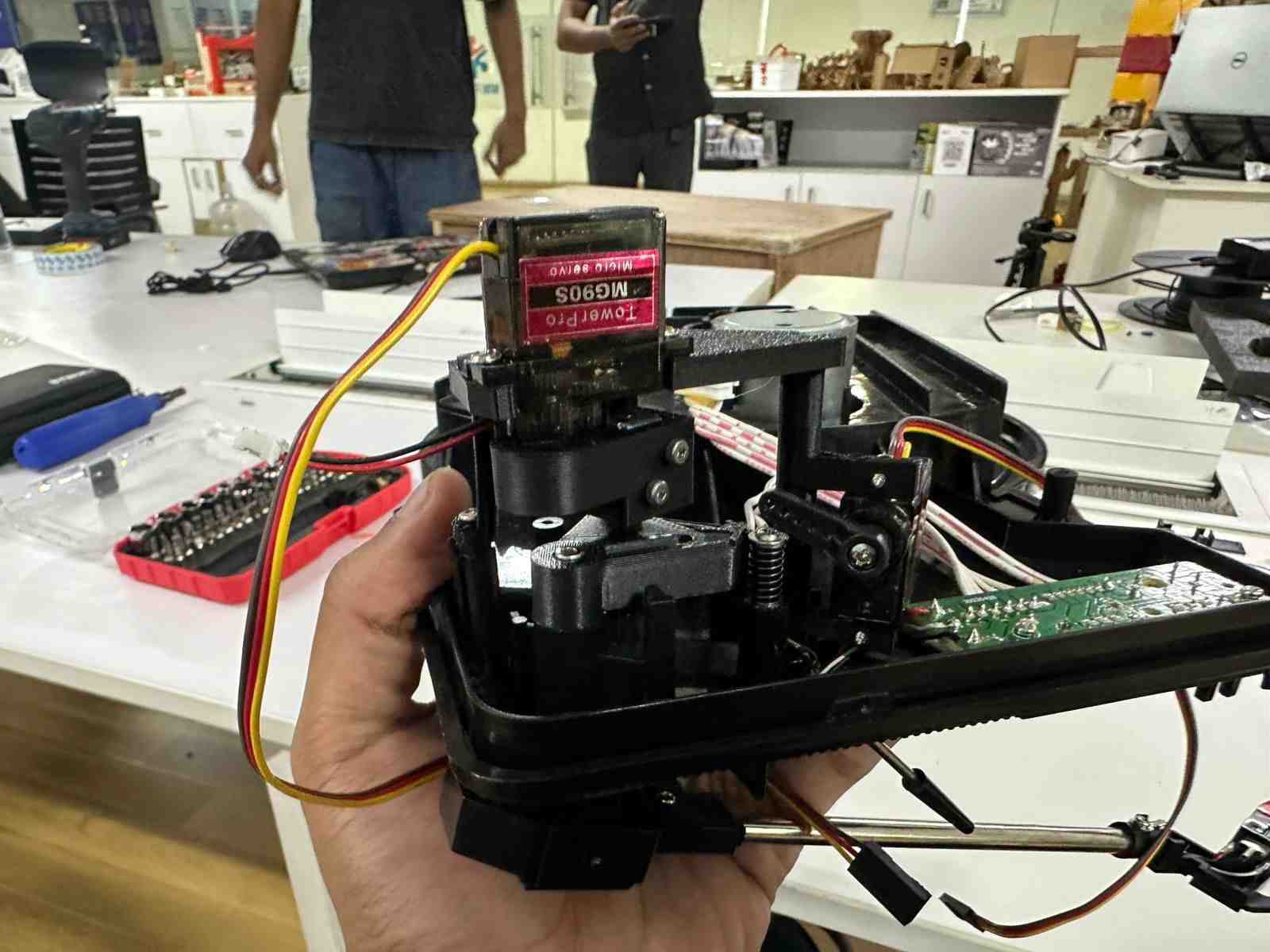
Finally assembled all parts and tested the functionality.
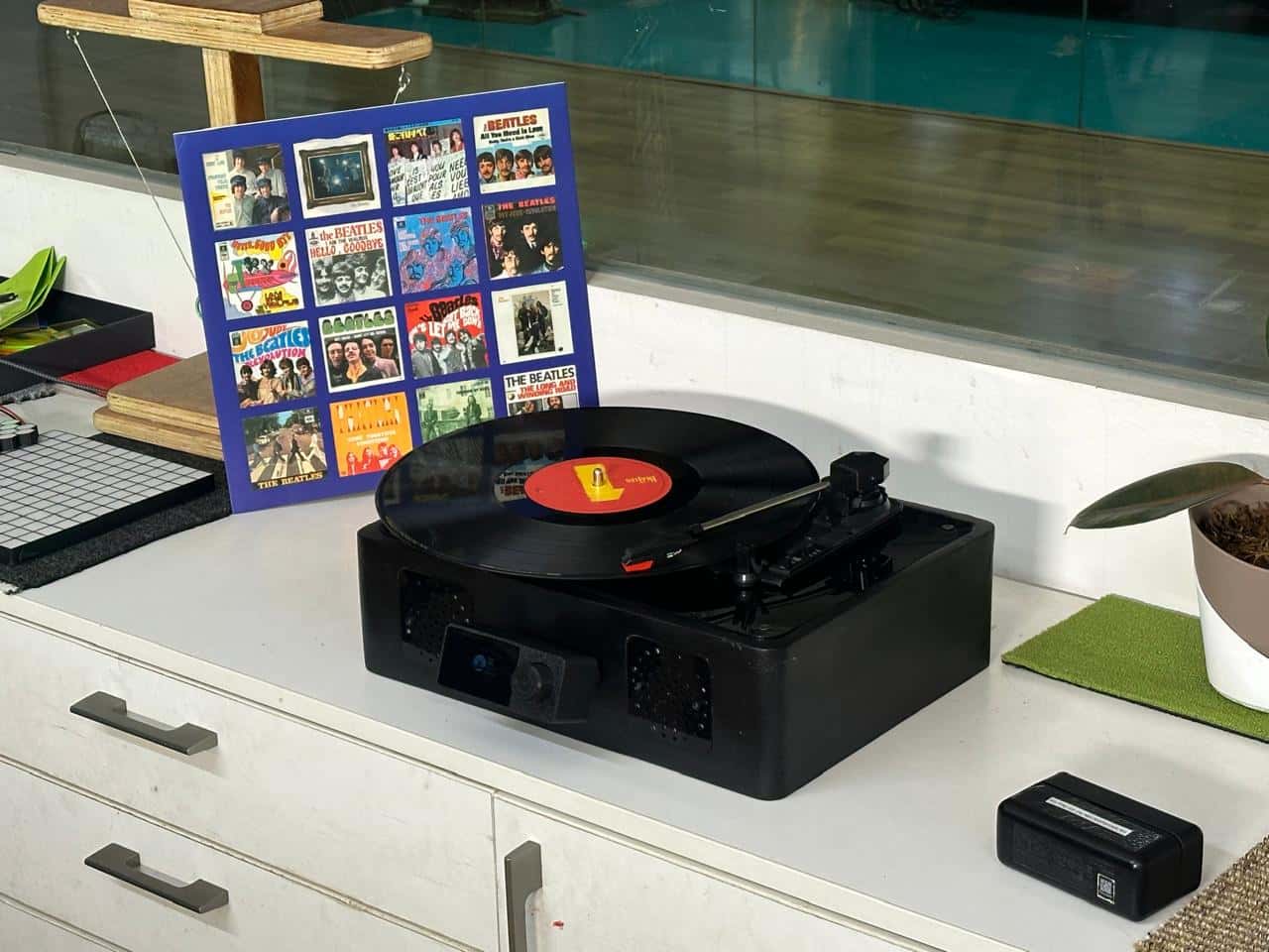
Firmware, Display, and Web App
With the physical build complete, work moved to the software side. This included firmware for the servo sweeping mechanism running on the XIAO ESP32-C6, software for the OLED display interface, and a companion web app.
.jpg)
Display Firmware and Working Demo
The web app, which hosts the Python detection script, was built by one of our lab guides, Midlaj, and can be found at fabsweep.web.app. The detection algorithm itself is available at github.com/MidlajN/vinyl_algorithm.
The system is designed to automatically detect track positions on a vinyl record from a single photograph of the record surface. The pipeline runs as follows: computer vision analysis to detect track positions, user verification of the detected tracks, storage in Firebase Realtime Database, and finally the player firmware reading that data to position the needle automatically.
Given a photo of a record, the algorithm estimates track separator positions, playable groove regions, label boundaries, overall vinyl geometry, and individual track segmentation.
The first implementation was backend-driven. This was a practical choice: Python's ecosystem already had mature libraries for this kind of work (OpenCV, NumPy, SciPy, and various signal analysis tools), which let development focus on whether the detection actually worked before dealing with additional infrastructure.
| Layer | Tech | Responsibility |
|---|---|---|
| Frontend | Firebase Hosted Web App | Upload image, preview, show detected tracks, confirm, save data |
| Backend | FastAPI + Python + OpenCV | Receive upload, run detection, return geometry and track data as JSON |
| Database | Firebase Realtime DB | Store confirmed positions, sync to hardware |
| Firmware | Device-side (XIAO ESP32-C6) | Read track metadata, position needle, enable song jump |
The overall workflow is: an image is uploaded, sent to the FastAPI /analyze endpoint, processed through the OpenCV pipeline (geometry detection, then playable area, then separator regions, then track segmentation), and returned as JSON. The frontend renders this for the user to confirm, after which Firebase RTDB is updated, and the firmware reads the confirmed data.
FastAPI was chosen for a few reasons: it allowed fast iteration on a detection pipeline that was changing frequently, it offered decent performance for CPU-heavy computer vision work behind a simple API, and it integrated with almost no friction into a pipeline that was already written in Python.
The firmware itself was first tested using hardcoded values before being connected to live data. The relevant sketch is linked below.
Full System Assembly
Project Status Summary
What tasks have been completed, and what tasks remain?
The mechanical build is essentially finished. The tonearm mechanism was redesigned around two servos instead of a servo-and-stepper combination, printed, and tested. The main PCB was designed, milled, and soldered, and a separate breakout board for the rotary encoder and OLED display was designed, milled, and tested for continuity. The enclosure was designed, milled from plywood on the ShopBot, sanded, sealed, and spray painted matte black, and the acrylic top and speaker mount were laser cut and fitted. The full unit is now physically assembled. On the software side, the web app for groove detection (built with FastAPI, OpenCV, and Firebase) is functional on its own, and the XIAO ESP32-C6 firmware for the servo sweep and display has been tested using hardcoded values. What remains is connecting the web app to the local firmware so detected groove data actually drives the hardware in real time, rather than the two working as separate, untested-together systems.
What's working? What's not?
The physical mechanism, enclosure, and both PCBs are all working as intended, confirmed through fit testing, continuity testing, and mechanical testing with cardboard and then acrylic mockups. The web app's detection pipeline works independently and produces track and geometry data from a photo. The firmware also works independently, correctly sweeping the servos based on hardcoded position values. What is not yet working is the link between these two halves: the web app and the on-device firmware have not been integrated, so groove data detected in the browser does not yet automatically reach and drive the XIAO over WiFi in practice.
What questions need to be resolved?
The main open question is how to reliably pass confirmed groove/track data from the Firebase-backed web app to the XIAO ESP32-C6 over WiFi in a way that's robust outside of hardcoded testing conditions. A related question is whether the camera-based detection approach should eventually move on-device, since an integrated camera module would remove the need for the web app entirely, but this raises questions about processing power and whether the same OpenCV-based approach can run efficiently on the device itself. There's also an open question around whether switching from the rotation servo to a solenoid would meaningfully improve positioning accuracy, and what that change would require from the current mechanism design.
Planned: what will happen when?
The immediate next step is integrating the web app with the local firmware so live detected data drives the physical mechanism end-to-end, closing the gap between the two systems that currently work only in isolation. Following that, the plan is to explore replacing the web app dependency with an integrated camera module directly on the device. As a further future improvement, the rotation servo may be replaced with a solenoid to improve positioning accuracy.