I was so excited for this week, imagining the machine doing all the magic while I just watched a cute crab come to life.
Then I remembered… I have to design it. From scratch. 😭
So instead of peacefully printing, I’m now learning how to actually design with YouTube as my emotional support system.
Let’s see how this goes. 🦀
How the week ended
This week ended well. I designed a component hinge that moves smoothly and can be modified to create articulatable objects.
The model worked without failure, and I’m considering making another one to 3D print.
I also experimented with 3D scanning using the Artec Leo scanner. Holding the scanner steady and adjusting the correct
scanning distance was a bit tricky, and the processing stage takes considerable time. I tried LiDAR scanning on an iPad as well,
which gave me better clarity on how to move and capture spaces effectively. Although the Artec Leo weighs 2.6 kg and seems heavy
for scanning larger areas, I was told it becomes manageable with practice.
Week 05’s assignment
Group assignment:
Test the design rules for your 3D printer(s).
Document your work on the group work page and reflect on your individual page what you learned
about the characteristics of your printer(s).
Design, document, and 3D print an object (small, few cm³, limited by printer time) that could not be easily made subtractively.
3D scan an object (and optionally print it).
Introduction to 3D Printing
3D printing is a process where we create physical objects from a digital design.
The object is made layer by layer using materials like plastic or resin.
There are different methods of 3D printing, depending on the material and technology used.
It is generally a slow process compared to traditional manufacturing.
There are also some restrictions on how a model can be printed. Sometimes,
the model needs support structures to print successfully without failing.
If a part of the model is hanging in the air (overhang), the printer cannot
print it without something underneath to hold it.
The machine follows instructions from the software and moves based on the
toolpath generated. The slicing software helps detect possible problem areas,
adds supports if needed, and shows whether printing in a certain orientation
is possible or not.
“Bambu Studio is an open-source, cutting-edge, feature-rich slicing software.
It contains project-based workflows, systematically optimized slicing algorithms,
and an easy-to-use graphical interface, bringing users an incredibly smooth printing experience.”
This software acts as the bridge between a 3D model and the physical 3D print.
To begin my 3D printing process, I installed
Bambu Studio from the official website.
One important thing I learned is that the 3D model can be designed in
any compatible modeling software. After modeling, the file
must be exported in a format supported by Bambu Studio.
Recommended & Supported Formats
Bambu Studio primarily accepts:
3MF (recommended – retains project settings)
STL
STEP / STP
OBJ
It also supports several additional CAD and 3D formats, including:
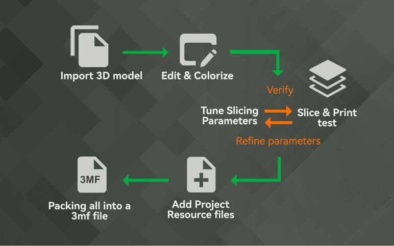
The workflow starts by designing the 3D model in any compatible software
and exporting it in a supported format (preferably 3MF).
The file is then imported into Bambu Studio, where print settings are adjusted
and the model is sliced to generate the file for 3D printing.
Through this process, I understood that Bambu Studio prepares the model
for printing acting as the bridge between digital design and physical production.
3D Model Making
Blender
While searching for a tutorial to help me design an articulated 3D print, I came across a Blender tutorial
on YouTube and followed it step by step in Blender to understand the modeling workflow.
Initially,I planned to design the complete articulated model; however, as I am still learning the software, I
decided to approach the task methodically and focus on understanding the fundamentals first.
Instead of modeling the entire assembly, I created a single module as a test run. This allowed me to
study the joint connection, evaluate the required tolerances for movement, and analyze how the parts
would interact when printed. By testing one module, I was able to better understand how the articulation
would function when repeated, ensuring that the final model would assemble correctly and move as intended.
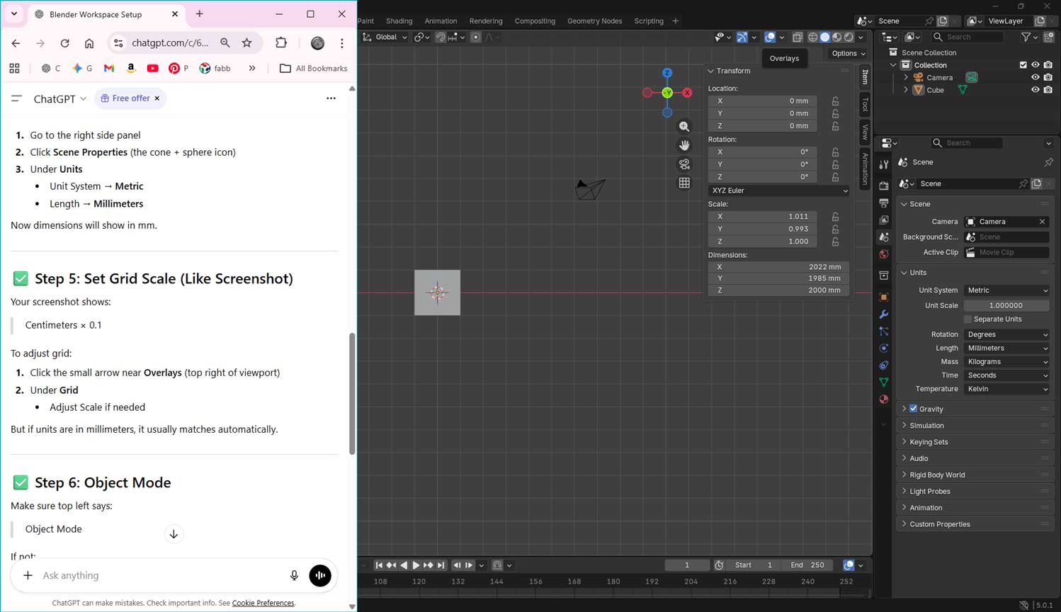
To begin modeling, I first configured my Blender workspace to match the setup shown in the tutorial video. Since I am new to Blender,
I wanted to ensure that my interface, unit system, measurements, and scale settings were aligned with the tutorial’s configuration.
I took a screenshot from the video and used ChatGPT to help me replicate the same workspace layout and technical settings.
Prompt used:
“I am trying to folow this youtube turoiral and use blender to create the model, help me set the same workspace,
including the measurements, scale, units. I am new to blender”
Phase 1: Base Geometry Setup
Create Cubes: In Object Mode, create two 20mm cubes. Right Click > Mesh > Cube. Position them with a 2mm gap between them.
Align View: Press 1 (Numpad) for Front Orthographic view and ensure Toggle X-Ray is ON to see the
internal geometry.
Add Main Pin: Add a Cylinder. Right Click > Mesh > Cylinder. Switch to Top View (7 or click Z-axis) and position it centrally on
the edge of Cube 1.
Adjust Height: Switch back to Front/Side view. Scale the cylinder so it is shorter than the cube’s
height and fits entirely within the cube's vertical bounds.
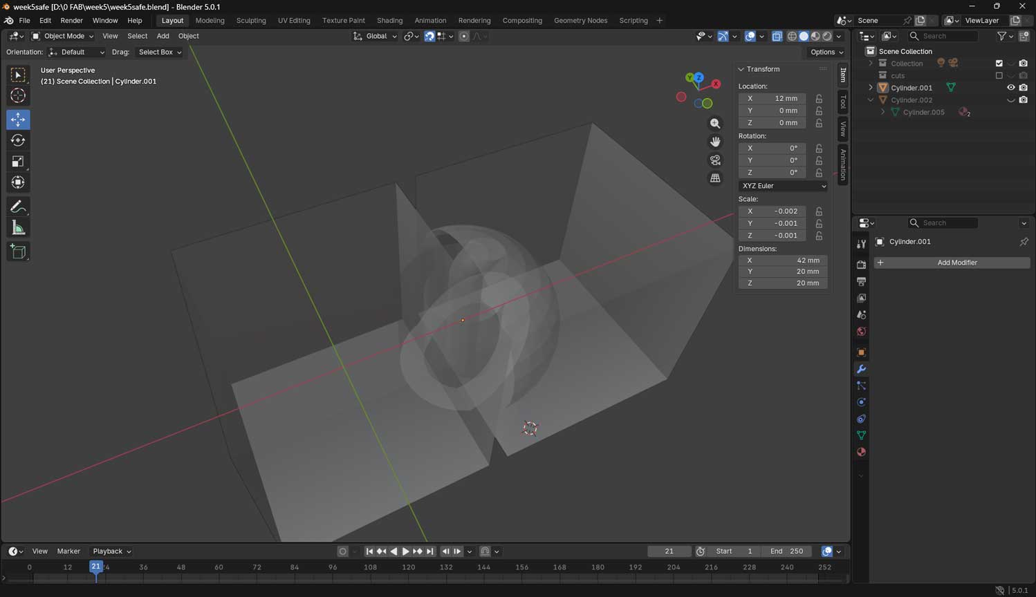
Phase 2: Creating the Hollow Housing (The Pipe)
Define the Cut: Duplicate the cylinder. Scale the duplicate smaller on the X and Y axes, but ensure its width is larger than the 2mm gap between the cubes.
Extend: Scale this smaller cylinder on the Z-axis so it extends outside the cubes (to ensure a clean cut).
Boolean Cut: Select the Large Cylinder, add a Boolean Modifier, set to Difference, and select the Small Cylinder as the object. Apply the modifier.
Result: The large cylinder is now a hollow vertical pipe.
Phase 3: Angling the Joint for Movement
Add Angular Cutter: Create a new, smaller Cube. Rotate it between 40–45 degrees.
Positioning: Place it so the edge of this rotated cube intersects the joint area. It should cut through the "pipe" and the edge of Cube 1 at an angle.
Boolean Cut: Apply a Boolean (Difference) to the Large Cylinder using the rotated cube.
Organization: Move the rotated cube to a "Cuts" collection and hide it.
Phase 4: Creating the Socket (The Dome)
Add Sphere: Create a UV Sphere. Scale it so it is large enough to contain the cylinder joint but small enough to remain inside the bounds of Cube 2.
Boolean Socket: Select Cube 2, apply a Boolean (Difference) modifier using the Sphere as the object.
Hide Sphere: Move the sphere to the "Cuts" collection.
Result: Cube 2 now has a spherical "dome" cavity that allows the joint to rotate freely.
Phase 5: Creating the Connecting Arm (The Hinge)
Extend Inner Pin: Take the innermost cylinder and extend it vertically.
Set Pivot Point: In Edit Mode, zoom in on the grid lines. Use Shift + Right Click to place the 3D Cursor on a grid intersection near the edge of the joint.
Spin Tool: Select the Spin Tool from the toolbar. Adjust the axis (X or Y) so the rotation arc moves toward Cube 2.
Extrude: Use the Spin tool to "sweep" the geometry into the sphere cut of Cube 2.
Clean Up: In Object Mode, use a Boolean on the cylinder with the cube if there is stray geometry, then delete unwanted vertices in Edit Mode.
Phase 6: Finalizing for Export
Join: Select all visible, non-cutter parts and press Ctrl + J to join them into a single mesh.
Verify: Check for any "non-manifold" geometry or touching faces that might fuse.
Export: Go to File > Export > Stl (.stl).
Export Issue: Blender to Bambu Studio
Initial Import Problem: After exporting the STL from Blender and importing it into Bambu Studio, the Boolean cutter objects appeared fused with the main model.
Hidden ≠ Deleted: The Boolean cutter objects were only hidden in Blender. Hidden objects are still exported unless deleted or excluded using “Selection Only”.
Unapplied Boolean Modifiers: The Boolean modifiers were not applied before export. Because of this, both the base mesh and cutter objects were included in the STL file.
Result in Slicer: Since Blender exports actual mesh data (not just viewport visibility), the slicer interpreted the hidden Boolean cutters as real geometry.
Corrections Made Before Re-Export
Apply Boolean Modifiers: Selected the main object → Opened Modifier Properties → Clicked Apply on each Boolean modifier to permanently merge the cuts into the mesh.
Delete Cutter Objects: After applying the modifiers, the Boolean cutter objects were no longer required and were completely deleted from the scene.
Join Mesh Parts: Selected all visible, non-cutter objects and pressed Ctrl + J to combine them into a single mesh (if exporting as one printable object).
Export with Correct Settings: File → Export → STL (.stl) → Enabled Selection Only (if necessary) and verified scale before exporting.
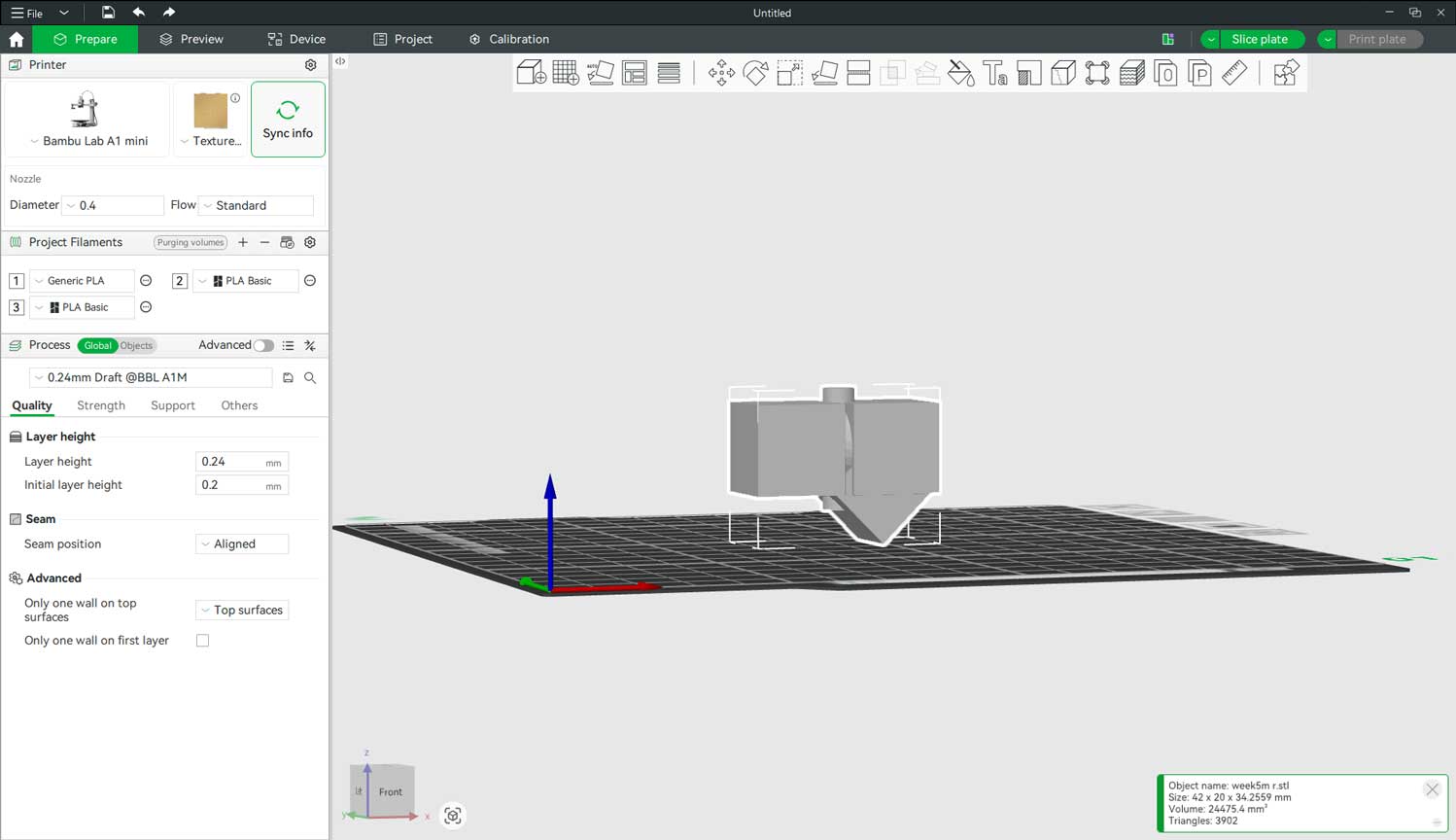
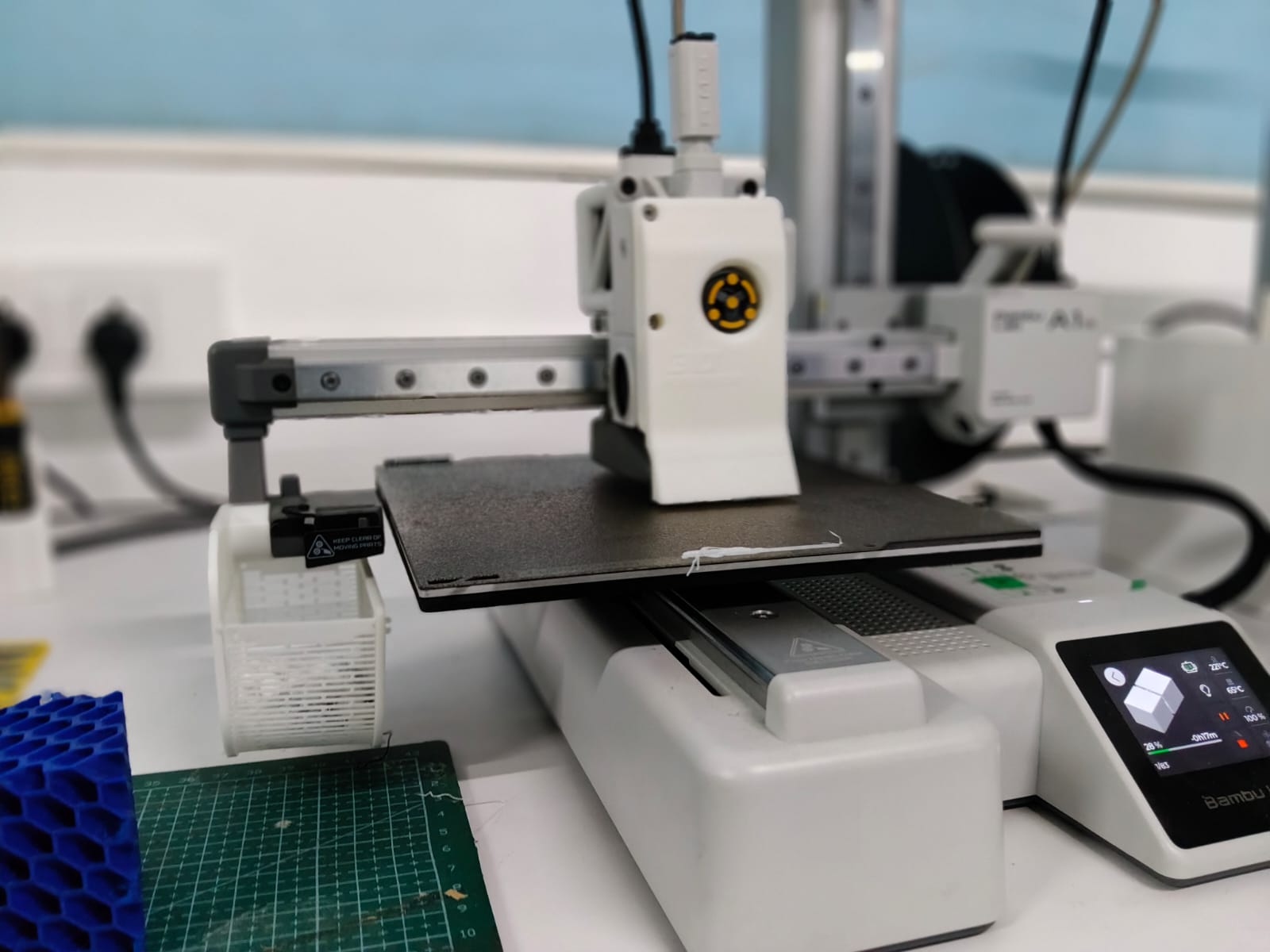
Phase 7: Preparing the Print in Bambu Studio
Connect to Printer: Connected the printer (Bambu Lab A1) to Bambu Studio and synced the device to retrieve filament information and printer status.
Automatic Profile Selection: In the Process toolbar, selected 0.24mm Draft @BBL A1M as the print profile.
Supports: Supports were not enabled because the model did not require them. The shaft overhang angles were approximately 45°, which is generally printable without support in FDM printing.
Default Settings: Apart from layer height selection, the remaining parameters were kept at default values (speed, infill, temperature, and wall settings).
Slicing: Clicked Slice Plate to generate the toolpath and previewed the layer-by-layer print simulation to verify print behavior.
Estimated Print Time: The total estimated print time was approximately 26 minutes.
Phase 8: Pre-Print Safety Checks
Build Plate Inspection: Ensured the build plate was clean and free from dust, filament residue, or debris to promote proper first-layer adhesion.
Plate Alignment: Verified that the build plate was properly seated and aligned on the printer bed.
Start Print: Sent the file to the printer and initiated the print job.
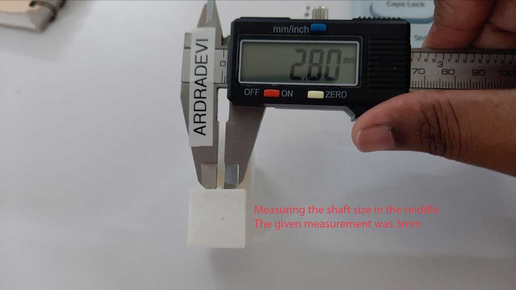
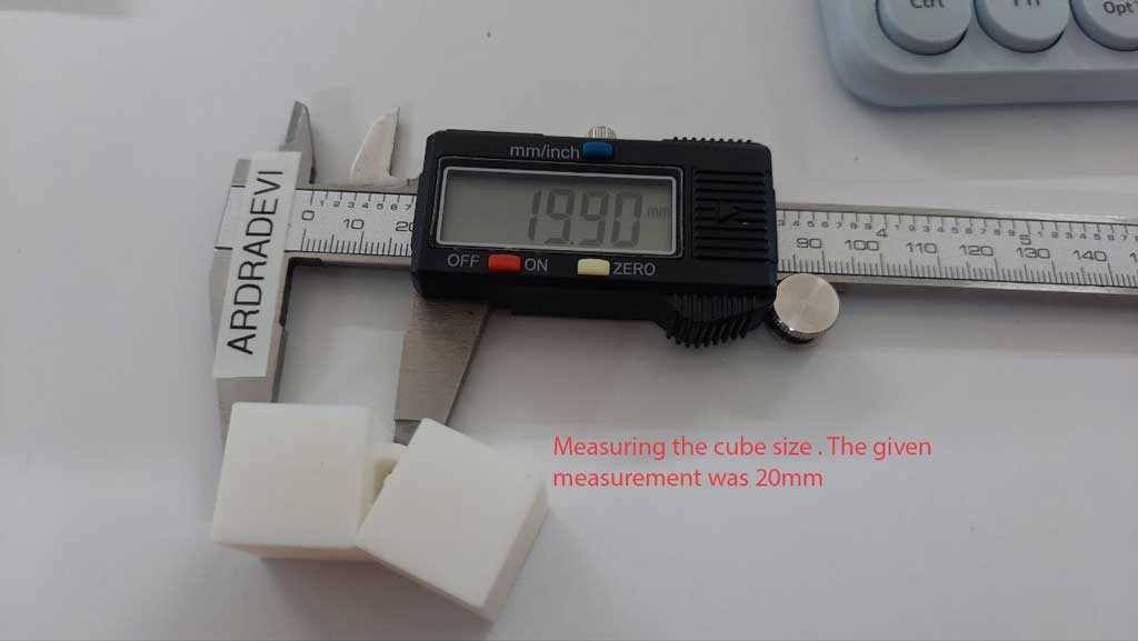
Phase 9: Post-Print Measurement and Dimensional Analysis
The model was designed in Blender with each cube dimension set to
20 mm (2 cm) per side. A central shaft was modeled with a diameter of
3 mm.
After printing the model using Bambu Studio, the physical dimensions
were measured using a vernier caliper.
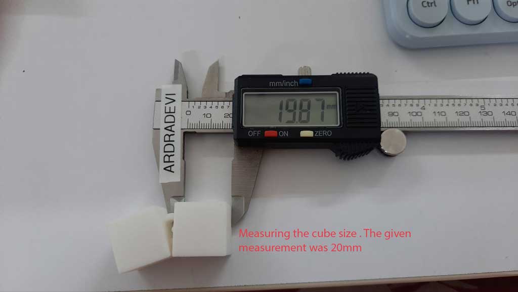
Measured Values:
Cube side (X direction): 19.90 mm
Cube side (Y direction): 19.87 mm
Central shaft diameter: 2.80 mm
Observations:
The cube shows a dimensional reduction of approximately
0.10–0.13 mm, indicating minor material shrinkage or printer tolerance variation.
The 3 mm shaft reduced to 2.8 mm, showing a shrinkage of
0.2 mm, which is more significant in smaller features.
Conclusion:
The printed model exhibits slight dimensional shrinkage compared to the
software-defined values. The deviation is within typical FDM printing
tolerance ranges; however, smaller elements (such as the 3 mm shaft) show
proportionally higher dimensional variation. Calibration adjustments or
tolerance compensation may be required for precision-fit components.
3D Scanner
The 3D scanner projects a structured light pattern onto the object. When the light hits the surface, the pattern deforms
based on the geometry of the object. Built-in cameras capture this deformation. Using triangulation principles, the system
calculates the distance of each point from the scanner. The collected data is converted into a point cloud and later processed
into a 3D mesh model.
Types of 3D Scanning Technologies
Structured Light Scanning – Uses projected light patterns and cameras. Artec Leo
Laser Scanning – Uses laser beams and triangulation.
Time-of-Flight (LiDAR) – Measures how long light takes to return. iPhone, iPad
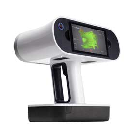
About the Scanner: The Artec Leo is a handheld, wireless 3D scanner that captures high-resolution
geometry and texture in real time. It has a built-in screen, so I could see the scan data live while moving around the object.
How It Works: The scanner projects structured light onto the surface and records how the pattern deforms.
From this, it calculates the 3D geometry of the object and generates a mesh model.
Adjusting Scan Distance: I was able to adjust and control the scanning distance depending on the object
size. Maintaining the correct distance helped me capture only the required object and avoid scanning unnecessary background space.
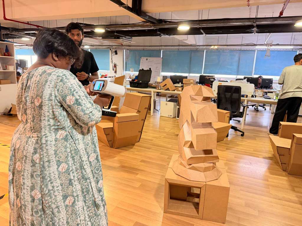
Scanning Process: I slowly moved around the object while monitoring the live feedback on the screen.
The scanner tracks geometry continuously, so smooth and steady movement was important to avoid data loss.
Object Scanned: I scanned a cardboard horse model. Since it had many planar surfaces and sharp edges,
maintaining consistent angles and coverage was important to ensure accurate edge detection.
Observation: Flat surfaces were captured clearly, but uniform areas required careful movement to
maintain tracking. Overlapping scan paths improved mesh accuracy.
3D Scanning Workflow Using Artec Leo and Artec Studio 15
I used the Artec Leo 3D scanner and Artec Studio 15 Professional to scan and process my model.
The scanner was connected to my system via WiFi (LAN connection can also be used for faster transfer).
1. Connecting and Importing the Scan
I turned on the Artec Leo scanner.
I connected my computer to the Leo’s WiFi network.
I opened Artec Studio and selected “Import scans from Leo.”
I selected the scanner from the list and clicked Connect.
I chose the required scan file and clicked Import.
I waited for the file transfer to complete.
After importing, the scan appeared in the Objects panel (top right corner).
I selected the scan to display it in the workspace.
2. Viewing and Navigating the Model
Left click + drag – Rotate the model
Scroll wheel – Zoom in/out
Middle click + drag – Pan
3. Initial Processing Using Autopilot
I used the Autopilot feature to process the scan automatically.
I clicked Autopilot.
The software guided me through Editing, Alignment, and Model Creation.
I kept most of the default settings (Scan quality: Good, Resolution: Auto).
I clicked OK and allowed the software to complete the processing.
This generated the initial mesh model.
4. Manual Editing (Cleaning the Base)
After processing, I noticed that the bottom of the model was inflated and not forming a flat plane.
To correct this, I manually edited the mesh.
I opened the Editor tool.
I held Ctrl + Left Mouse Button to select the unwanted region.
I clicked Erase to remove the selected area.
I repeated this process until the base was clean and properly defined.
5. Fixing Holes
After erasing the unwanted geometry, the bottom surface became open.
To close the mesh, I used the Fix Holes tool.
I selected Fix Holes.
I chose the Watertight hole-filling method.
I kept the resolution on Auto.
I applied the settings.
This successfully filled the base and created a closed, printable mesh.
6. Improving Alignment (If Required)
If needed, I used Global Registration under Tools to improve alignment accuracy
between scan frames and enhance geometric precision.
7. Mesh Optimization
Before exporting, I simplified the mesh to reduce the polygon count while maintaining sufficient detail.
This makes the file easier to handle in other software and suitable for 3D printing.
8. Exporting the Model
I went to File → Export Mesh.
I exported the model as:
STL – for 3D printing (geometry only)
OBJ – for textured model export
I selected the save location and completed the export.
9. Saving the Project
Finally, I saved the project as an .a3d file to retain the raw scans,
processing steps, and editing history for future modifications.
Conclusion
Through this workflow, I successfully scanned, processed, cleaned, and exported a complete 3D model
using Artec Leo and Artec Studio. The combination of Autopilot processing and manual editing
ensured accurate geometry and a clean base suitable for further applications.
.jpg)
.jpg)
.jpg)
.jpg)
.jpg)
.jpg)
.jpg)
.jpg)
.jpg)
.jpg)
.jpg)
.jpg)
.jpg)
.jpg)
.jpg)
.jpg)
.jpg)
.jpg)
.jpg)
.jpg)
.jpg)
.png)
.jpg)
.png)
.jpg)
.jpg)
.jpg)
.jpg)
.jpg)
.jpg)
.jpg)
.jpg)
.jpg)
.jpg)
.jpg)
.jpg)
.jpg)