WEEK 3
Computer-Controlled Cutting
How the week started
Last week, I learned about different software for 2D and 3D designing. Finally will be using machines, this week we are introduced to Vinyl cutter and Laser cutting process. Hope to design cool stickers.
How the week ended
This week was a revelation in efficiency. Having spent years manually cutting architectural models by hand, I’ve realized just how much these machines could have transformed my workflow. It’s exciting to see how this technology can turn the most tedious parts of model-making into something genuinely fun and precise.
Week 03’s assignment
Group assignment:
• Lab’s safety training
• Characterize lasercutter’s focus, power, speed, rate, kerf, joint clearance and types.
• Document our work to the group work page and reflect on my individual page what I learned.
• Design, lasercut, and document a parametric construction kit, accounting for the lasercutter kerf.
• Cut something on the vinyl cutter.
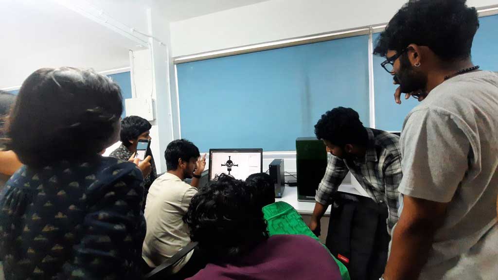
Meeting the machines

Promt : I added the image of dobby meme and then added the promt " similar to this. i want to create meme a funny meme.in fab academy finally we are getting access to machines which everyone was waiting to try. we were elarning CAD for 2 weeks. say something funny about it like fab academy restricted us to cad and now we have acess, malfboy here is the academy "
Group assignment
Lab’s safety training
Safety is the most important part of working in the Fab Lab. The lab contains powerful machines, sharp tools, and materials that can be dangerous if not handled properly. Therefore, it is essential to follow all safety guidelines before using any equipment.
During the safety training, I understood and followed these basic safety measures:
- Always wear proper personal protective equipment (PPE) such as safety glasses, closed-toe shoes, and gloves when required.
- Avoid loose clothing, accessories, and keep long hair tied back.
- Keep the workspace clean and free from unnecessary materials.
- Check machines before use and inform the instructor if something seems wrong.
- Know the location of emergency stops, fire extinguishers, first-aid kits, and exits in the lab.
- Pay attention to all safety instructions given by the lab staff.
CO₂ Laser Cutter Safety
The CO₂ laser cutter is a powerful machine used for cutting and engraving materials with high precision. However, it can be dangerous if not used carefully. The laser beam is extremely strong and can cause burns, fire, or eye damage.
It is important to use only approved materials in the laser cutter. Materials like PVC and ABS should not be used because they release toxic fumes when burned.
The laser cutter has an exhaust system that removes smoke and harmful fumes during cutting. This must always be switched on while operating the machine.
What to do if a fire starts inside the laser cutter:
- Do not open the lid immediately.
- Pause the machine if it is safe to do so.
- If the flame is small, cover it with a non-flammable material.
- Observe carefully without panicking.
- Use a CO₂ fire extinguisher if necessary.
- Call for help and evacuate if the fire cannot be controlled.
Vinyl Cutter Handling Safety
- Ensure the blade is installed correctly and set to the right depth.
- Align the vinyl sheet properly before cutting.
- Keep hands away from moving parts of the machine.
- Pause the machine before removing jams or adjusting the sheet.
- Remove extra vinyl carefully using a weeding tool.
Vinyl Cutting – Basic Understanding
Vinyl cutting is a process where a computer-controlled machine uses a small sharp blade to cut designs from vinyl sheets based on vector drawings.
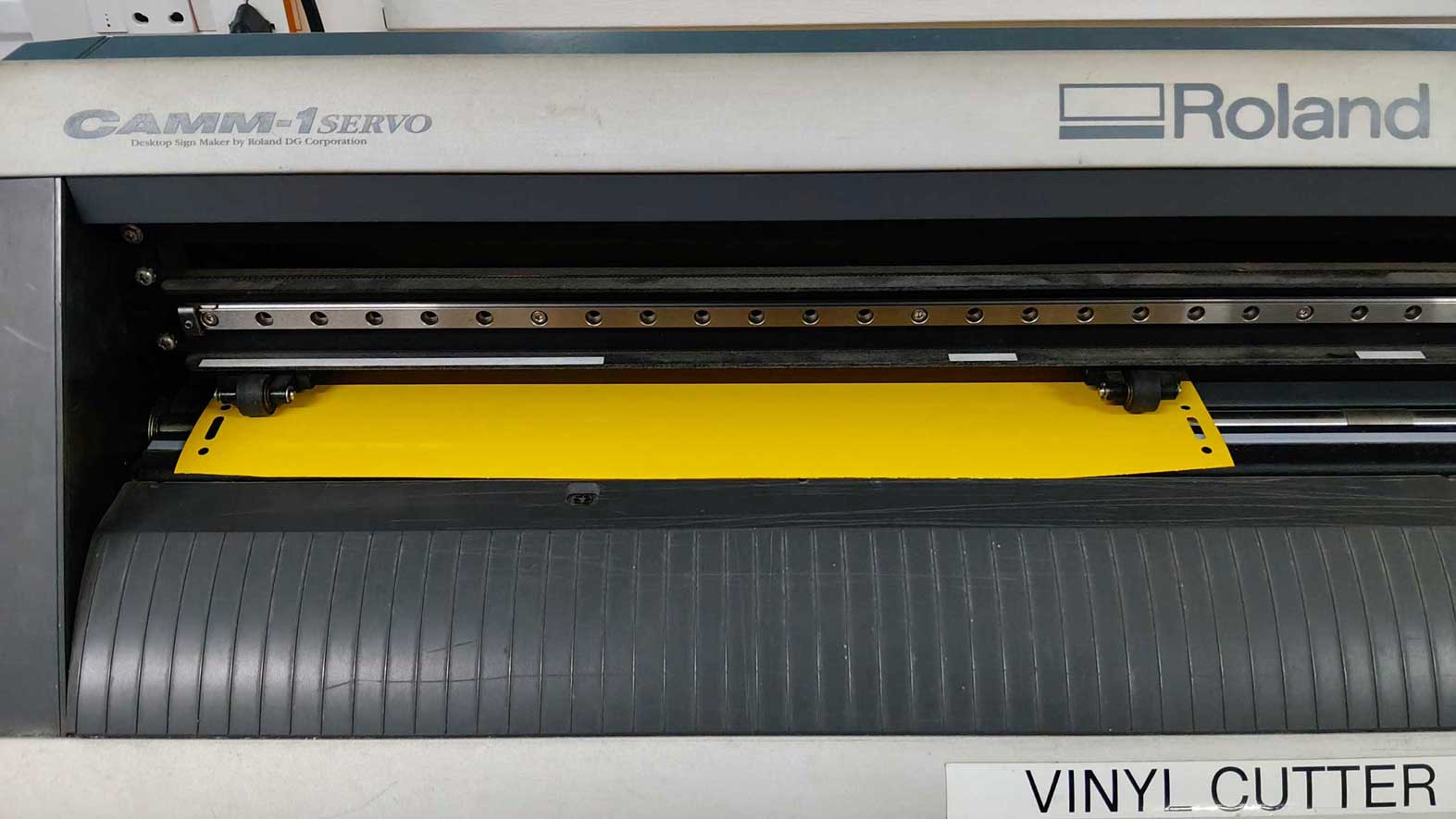
Roland GX-24 Vinyl Cutter
In our lab, we use the Roland GX-24 vinyl cutter. There are two types of vinyl cutters: active and passive.
Active cutters use a motor to control the blade direction, while passive cutters rely on the movement of the cutting head to rotate the blade naturally. The Roland GX-24 is a passive cutter, but it is still fast, accurate, and reliable for high-quality vinyl cutting.
Other Materials
We cut different materials like cardboard, wood, and acrylic on the laser cutter. The kerf values were different for each.
𝐾𝑒𝑟𝑓 = 𝑇𝑜𝑡𝑎𝑙 𝐺𝑎𝑝 / 2
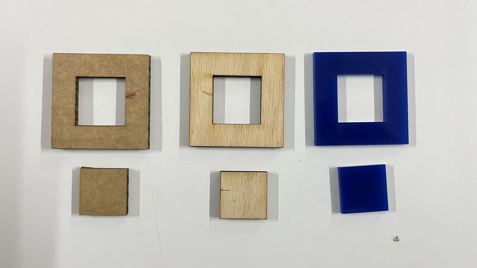
The kerf value for cardboard is more. That means more of the material is removed from cardboard. Cardboard is easily flammable.
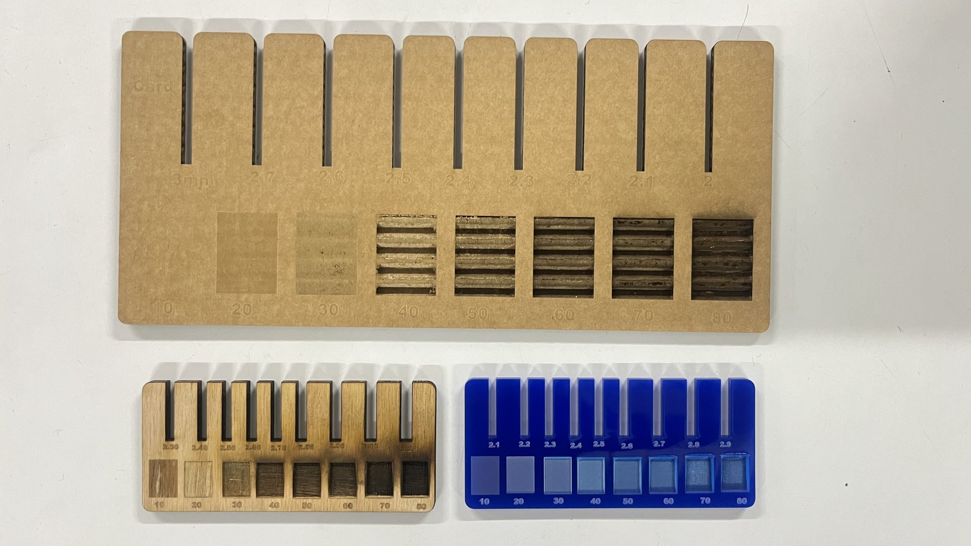
Jig
A jig is designed to find the fit between the materials. This helps us during the designing process. For example, in the following woodworking week, this would come in handy. Because of the kerf value, the material cut off from each part would sometimes make it a loose fit. A jig is used to determine which value would provide a good fit. Jigs similar to this help during your final project when you do not have time to make a jig for each and every part.
For more info: Refer group assignment
Individual assignments
Vinyl cutter
The Roland GX-24 (CAMM-1 SERVO) -more infor is a desktop sign maker and high-performance cutting machine designed for high-quality precision cutting.
- Used for signs, stickers, decals, and apparel prints
- Uses a digital servo motor for smooth cutting
- Can cut materials from about 50 mm to 700 mm wide
- Works with different materials like:
- Adhesive vinyl
- Heat-transfer vinyl
- Paint mask
- Reflective sheets
Preparing the Design (Inkscape – Computer Station)
The vinyl cutter used in the Fab Lab is a Roland GX-24. It operates using a small knife controlled by a solenoid, which applies adjustable cutting force onto the vinyl sheet. The cutting force must be set based on the thickness of the vinyl material to ensure a clean cut without cutting through the backing sheet.
Vinyl cutting works with vector-based images, which allow precise paths for the machine to follow. For this project, I used Inkscape to create and prepare my design for cutting.
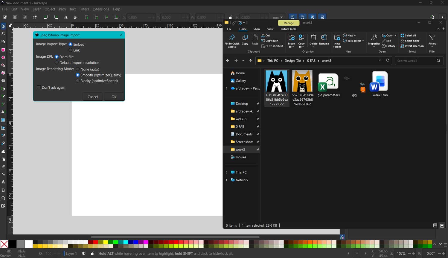
I selected an illustrated image of a cat from the web and imported it into Inkscape by dragging and dropping the file onto the workspace. The image had minimal colors and clear outlines, making it suitable for vector tracing.
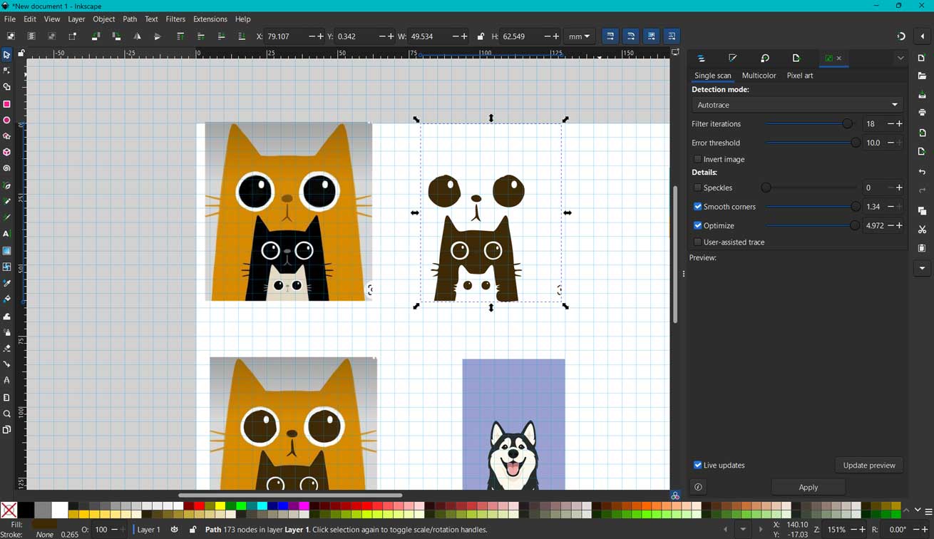
Using the Trace Bitmap tool in Inkscape, I converted the raster image into a vector format. After tracing, I cropped and cleaned up the image to keep only the portion I needed for the sticker.
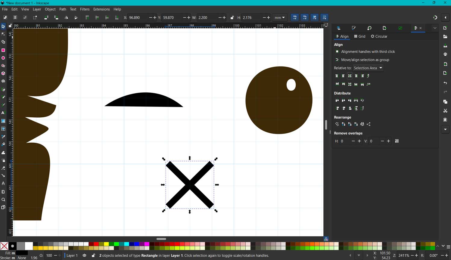
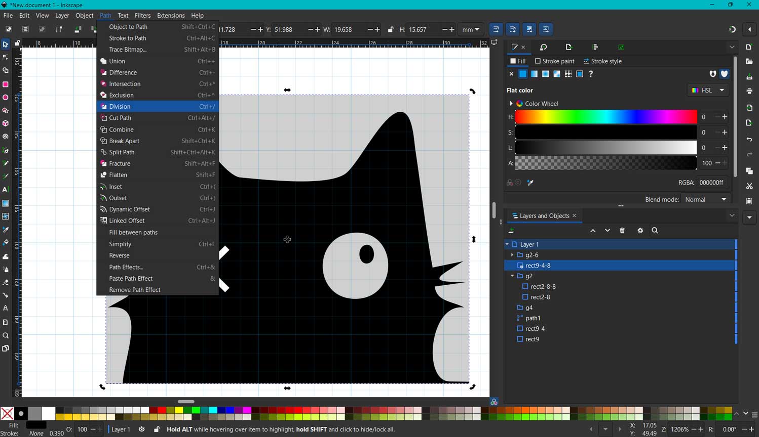
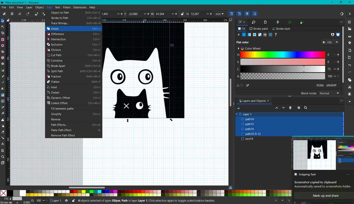
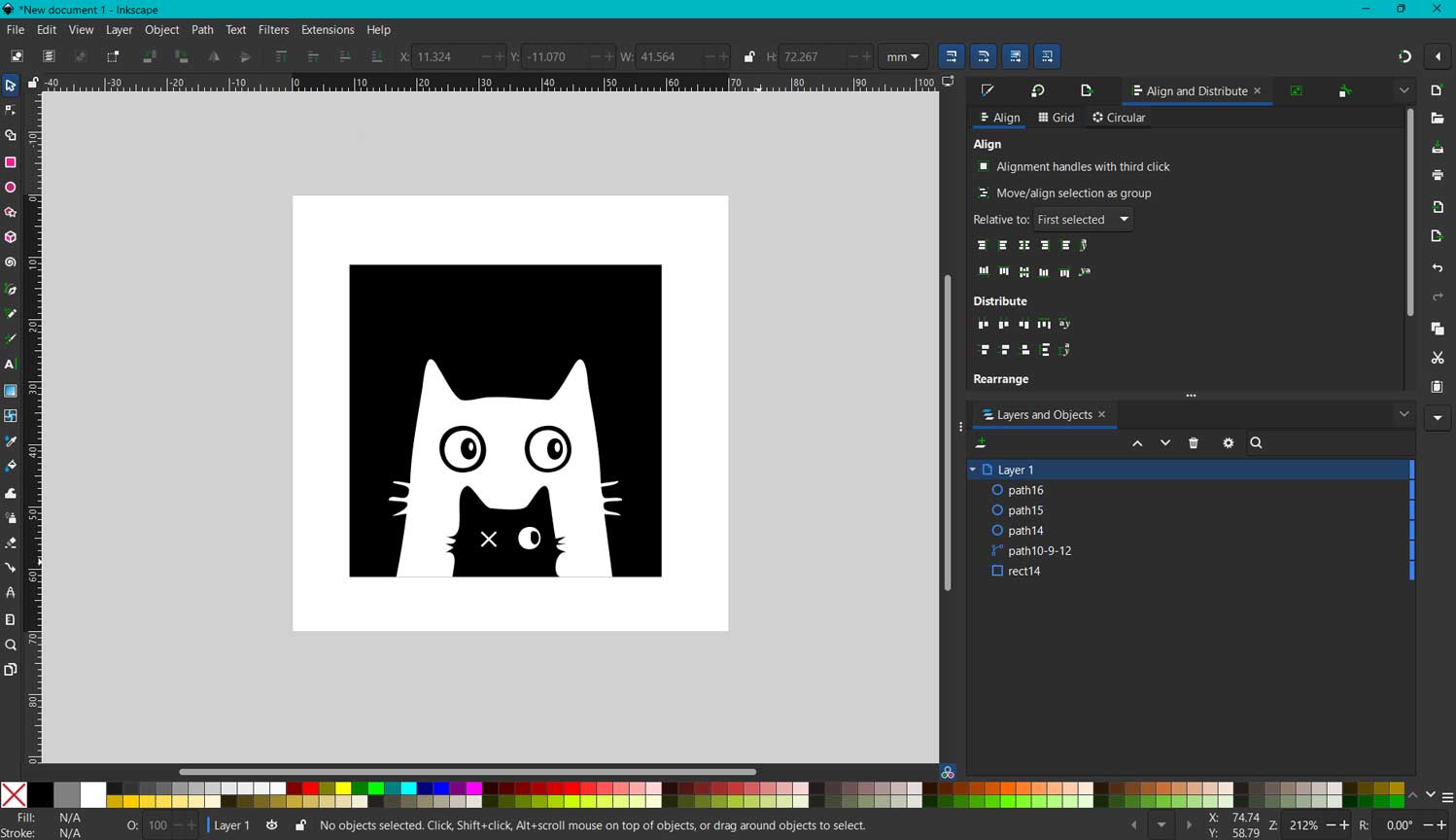
I edited the cat’s eye and separated design elements using the Division tool. This allowed me to isolate the small cat from the background. I then rearranged and unioned the larger cat shape behind it so that the small cat and background shared the same color layer while retaining fine details.
ModsProject
MODS Project is a web based software used in digital fabrication. It was developed by the MIT Center for Bits and Atoms and is widely used in Fab Labs and Fab Academy. The images we use are in different formats, but machines do not understand what a PNG, JPEG, or SVG file is. This software helps convert design files into machine instructions or machine readable language that can be understood by machines such as CNC routers, PCB milling machines, laser cutters, vinyl cutters, and 3D printers.
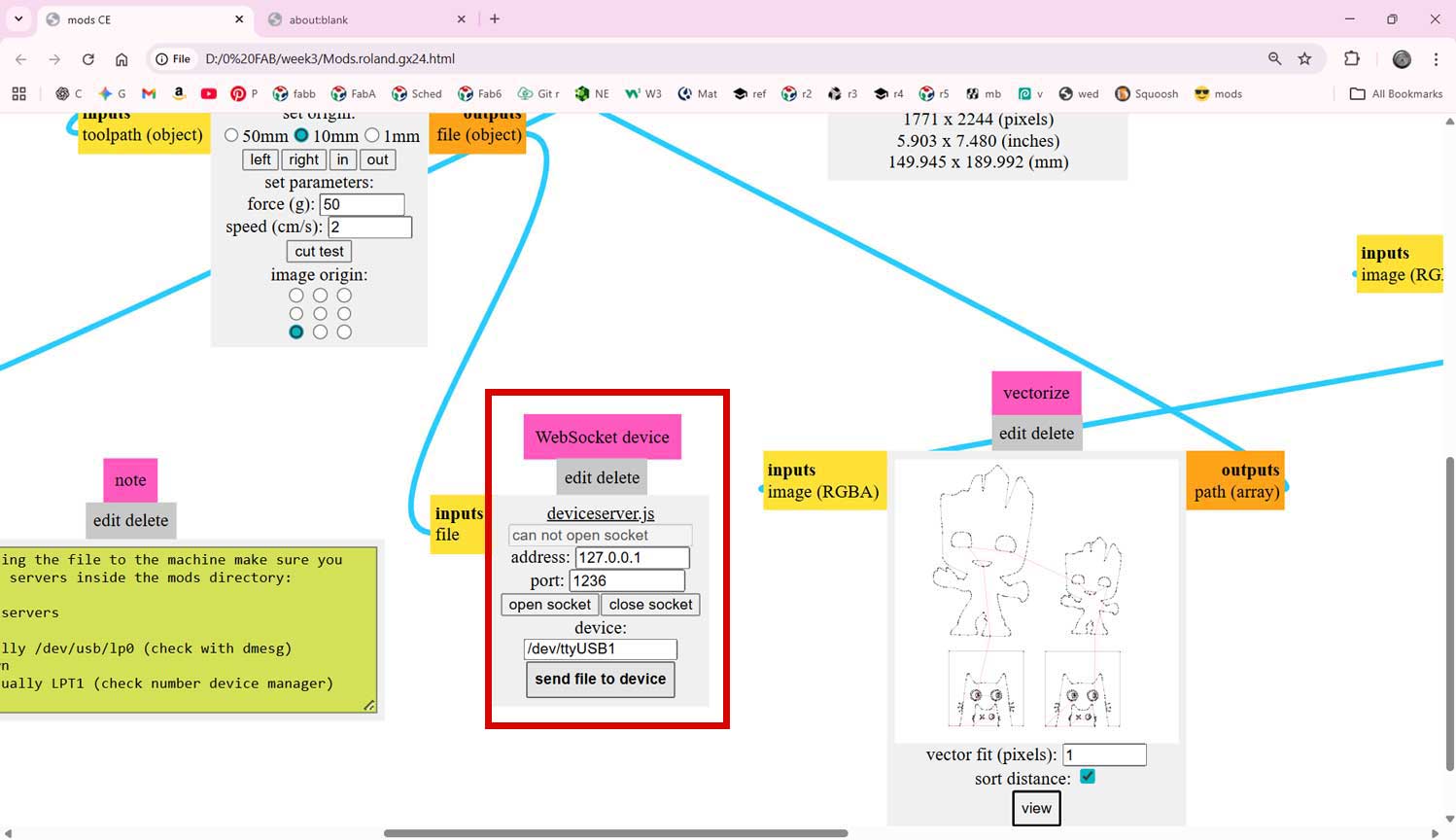
Next, I opened modsproject.org in
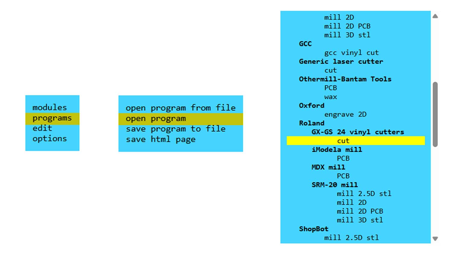
my browser. In the Mods interface, I right-clicked inside the workspace and selected:
PROGRAMS → OPEN PROGRAMS → Roland → GX-24 vinyl cutters → CUT.
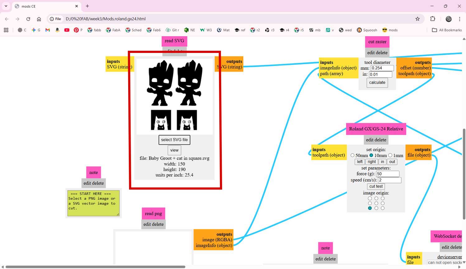
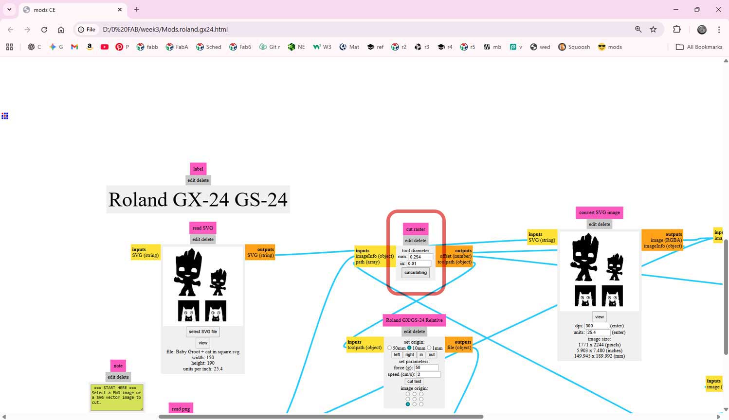
In the modules that appeared, I uploaded my file into the SVG read module by selecting the SVG format. I then clicked Calculate to preview the cutting path before sending it to the machine.
Before sending the file, I prepared the vinyl cutter. I loaded the vinyl sheet into the machine and selected “Roll” mode on the control panel. Using the arrow keys on the machine, I adjusted the position of the cutting head.
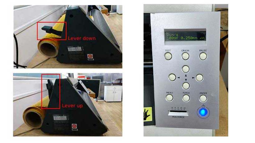
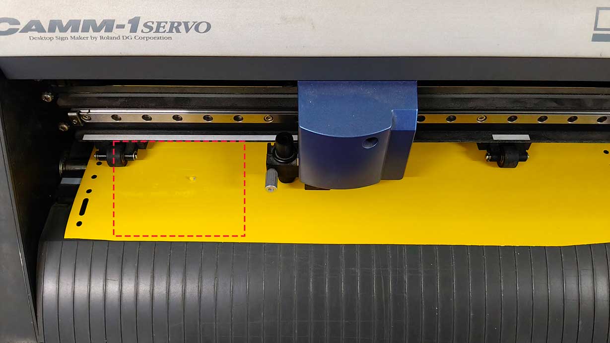
I aligned the pinch rollers to match the width of my vinyl sheet so that it would be held firmly in place. I also moved the knife manually to check the available cutting length on the sheet.
To ensure proper cutting depth, I performed a test cut. This helped verify that the blade pressure was correct and that the cut would be clean.
I am combining my file with Merin's svg file. Thats why Groot appears in mods.
Once satisfied, I clicked “Send to Device” in the Mods interface. The machine then began cutting the design following the vector paths.
Since my sticker had two colors, I repeated the same process for the second sheet of vinyl. For this I uploaded only my file.
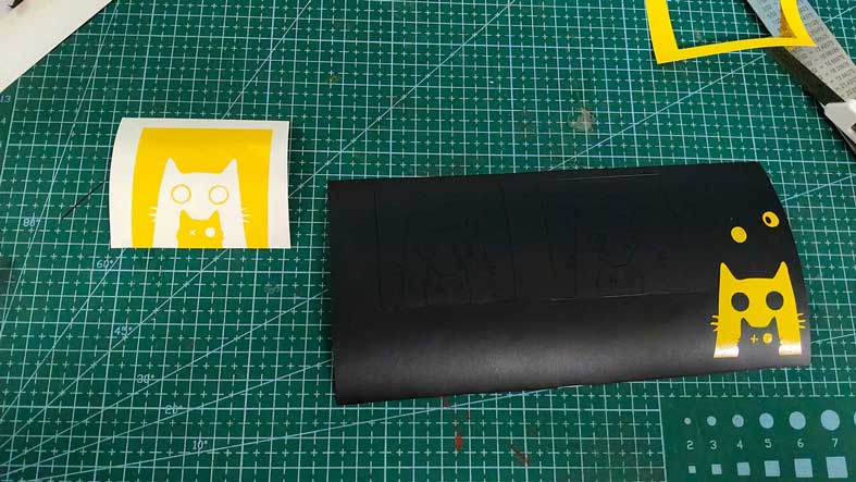
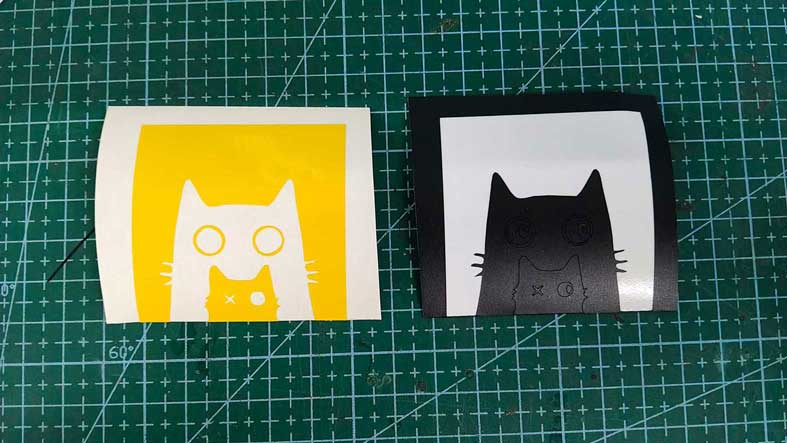
After cutting, I weeded the vinyl using tweezers and a weeding tool. I removed the unwanted background from the black sheet and kept only the small cat shape. On the yellow sheet, I removed the cat shape instead, keeping the background.
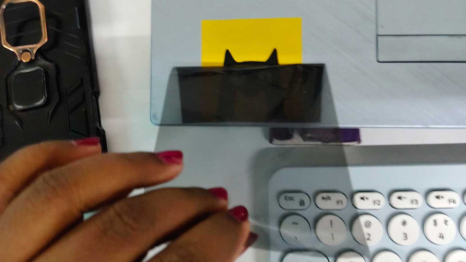
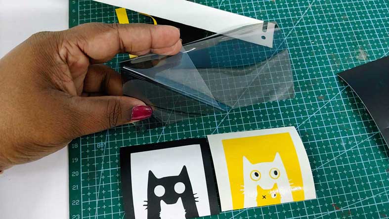
I placed transfer tape - cooling film over the black vinyl design, pressed it firmly, and lifted it carefully from the backing sheet. I then aligned the black cat's outline to the negative space of it in the yellow sheet and pasted it onto the yellow vinyl layer.
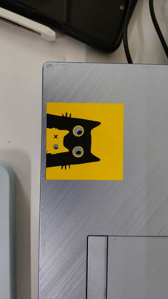
Finally, I cleaned the laptop surface with a cloth to remove dust and grease. I placed the sticker on the surface, pressed it evenly with a squeegee, and slowly peeled off the transfer tape - cooling film, leaving the sticker perfectly applied.
Laser cutter - Trotec SPEEDY100
Designing in Fusion
For this assignment, I used Autodesk Fusion 360 to create templates for the construction kit pieces. I worked in the Hybrid Design workspace and began by creating basic shapes in the Create Sketch environment.
Parametric Values used is added at the end of this paragraph.
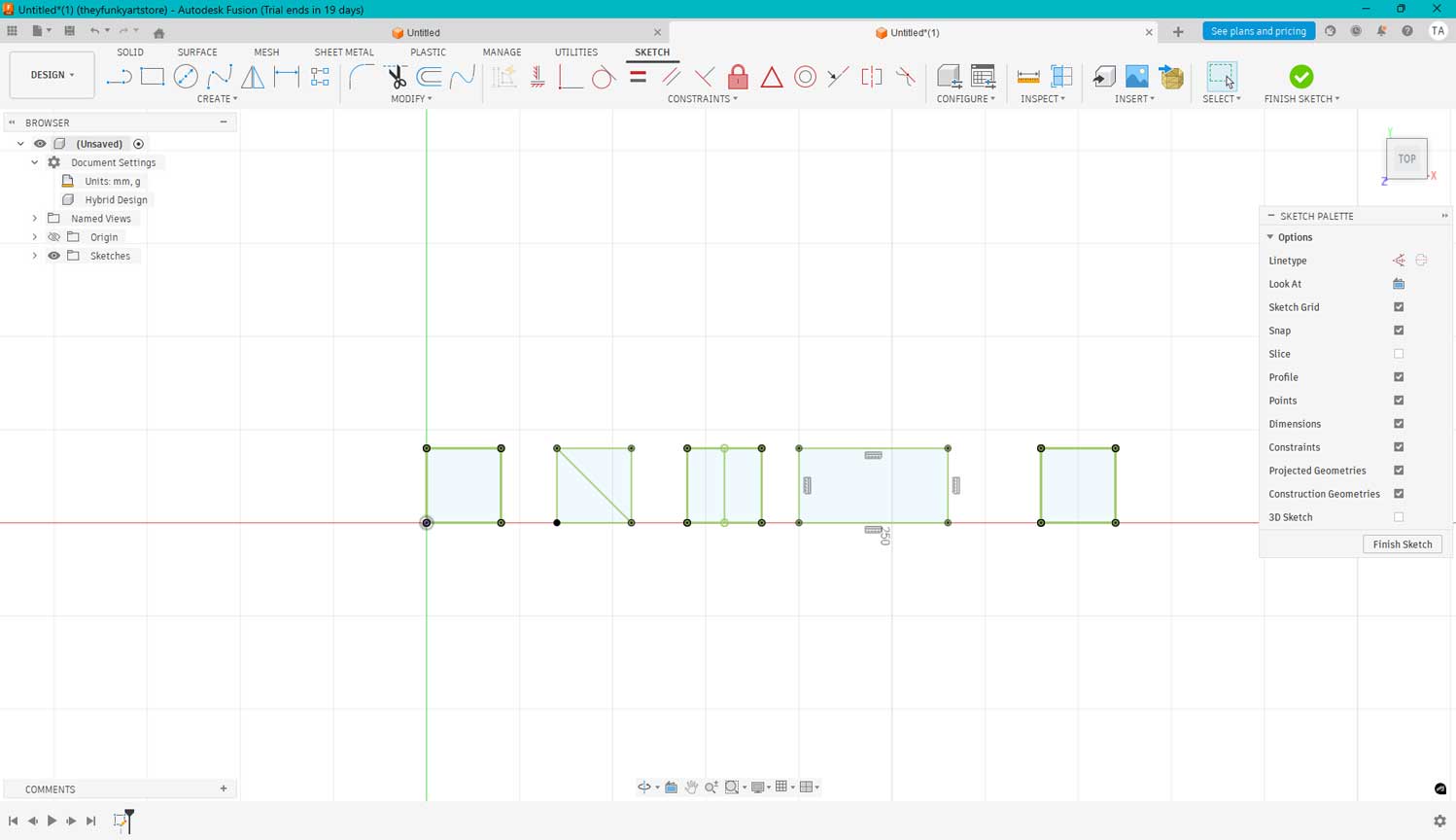
I constrained the shapes to fix their positions and added parametric values for the cut slots. These values depend on the material thickness and the kerf value of the laser cutter. From our group experiment, we identified suitable kerf values for cardboard.
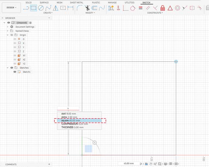
For example, along this side I drew a square, and for one side I am using the parametric value that I had already added. So, if I want to change the value, I can change it in the parameters rather than changing each and every length individually.
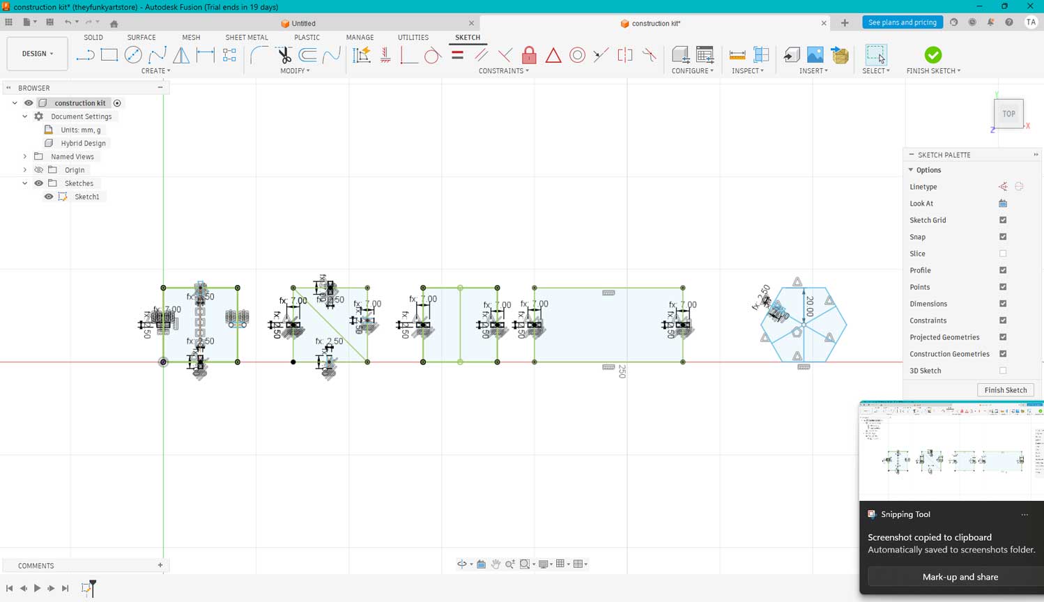
I aligned the slots to the center of each piece and created rectangles using the center-rectangle tool. This ensured a fully parametric design that could be easily modified later.
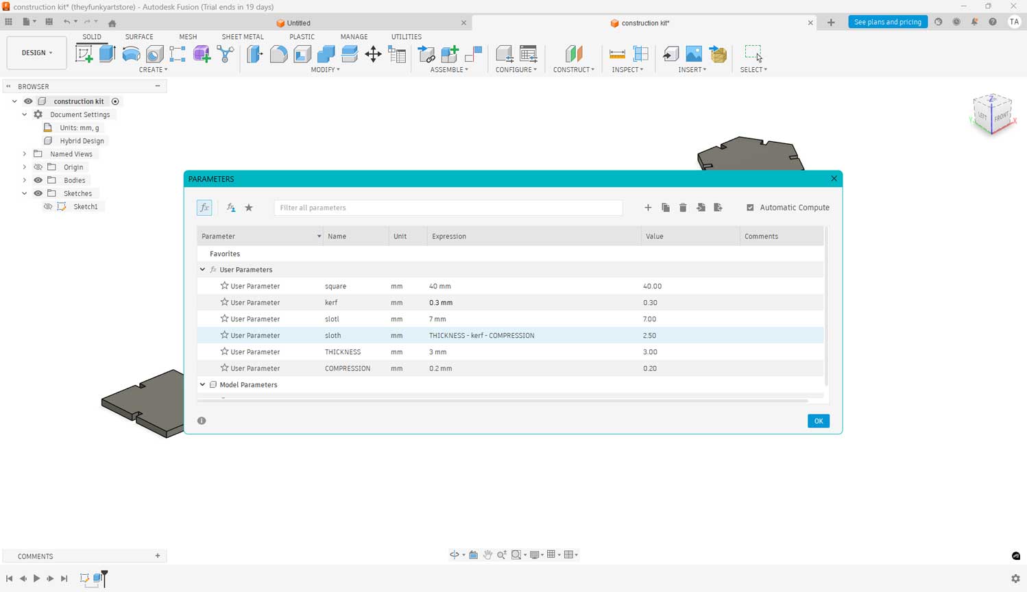
The slot width was calculated as: Material thickness – kerf value – compression tolerance.
Extrusion and Export
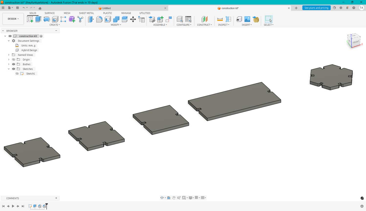
After finishing the sketches, I clicked Finish Sketch and extruded the shapes to 3 mm, matching the thickness of the cardboard we planned to cut.
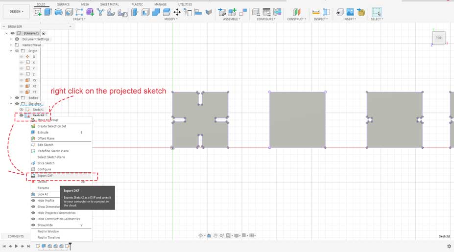
I then projected the final outlines and exported the file as a DXF format, which is compatible with laser cutting software.
Preparing the File in Inkscape
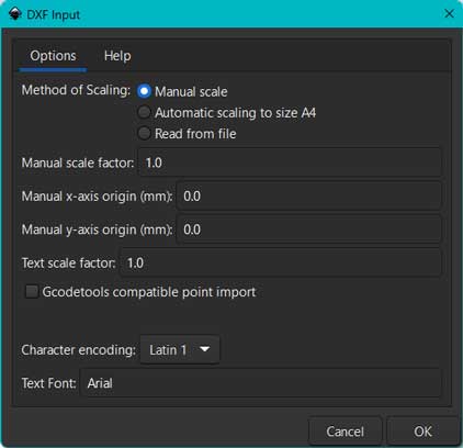
I imported the DXF file into Inkscape. In the DXF import dialog box, I selected Manual Scale to prevent automatic resizing. This ensured the file remained at the correct real-world scale.
Test cut design in inkscape
Test cut and assembling.
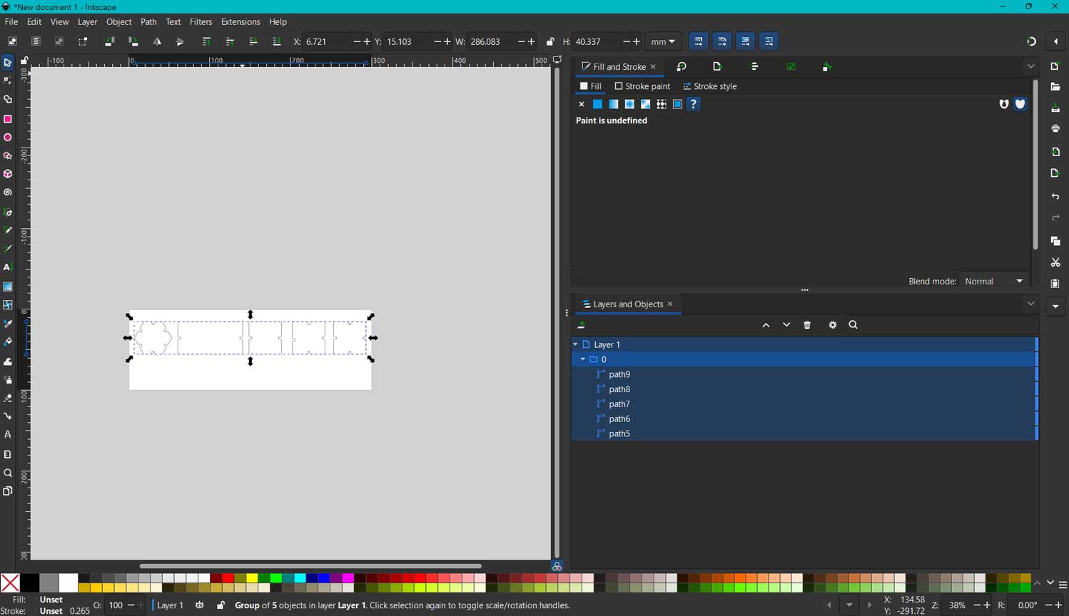
After importing, I adjusted the canvas to fit the drawing using Ctrl + A and then Ctrl + Shift + R. I also set the correct units and kept the rulers visible to understand the area occupied on the sheet. I copied the whole image with ctrl+a and then rotated it holding the controls at the corner and then pasted it.
The below is what was manually arranged for the lazercutter. One could do this arrangement in Fusion using Modify > Arrange. and then duplicate it in inkscape
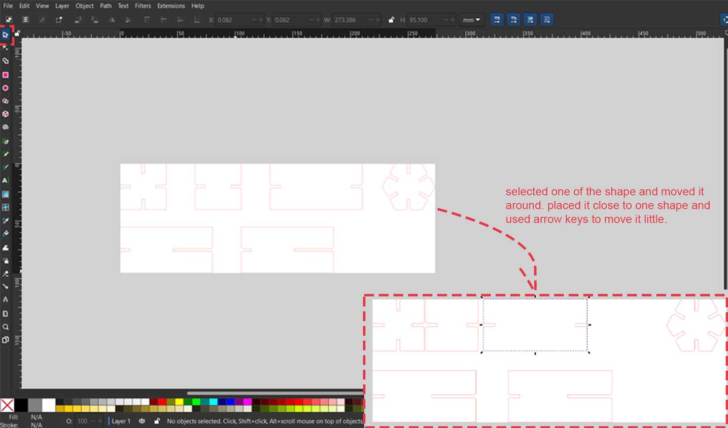
I manually rearranged the pieces in Inkscape to optimize material usage. I duplicated some parts using Ctrl + D where multiple copies were needed.
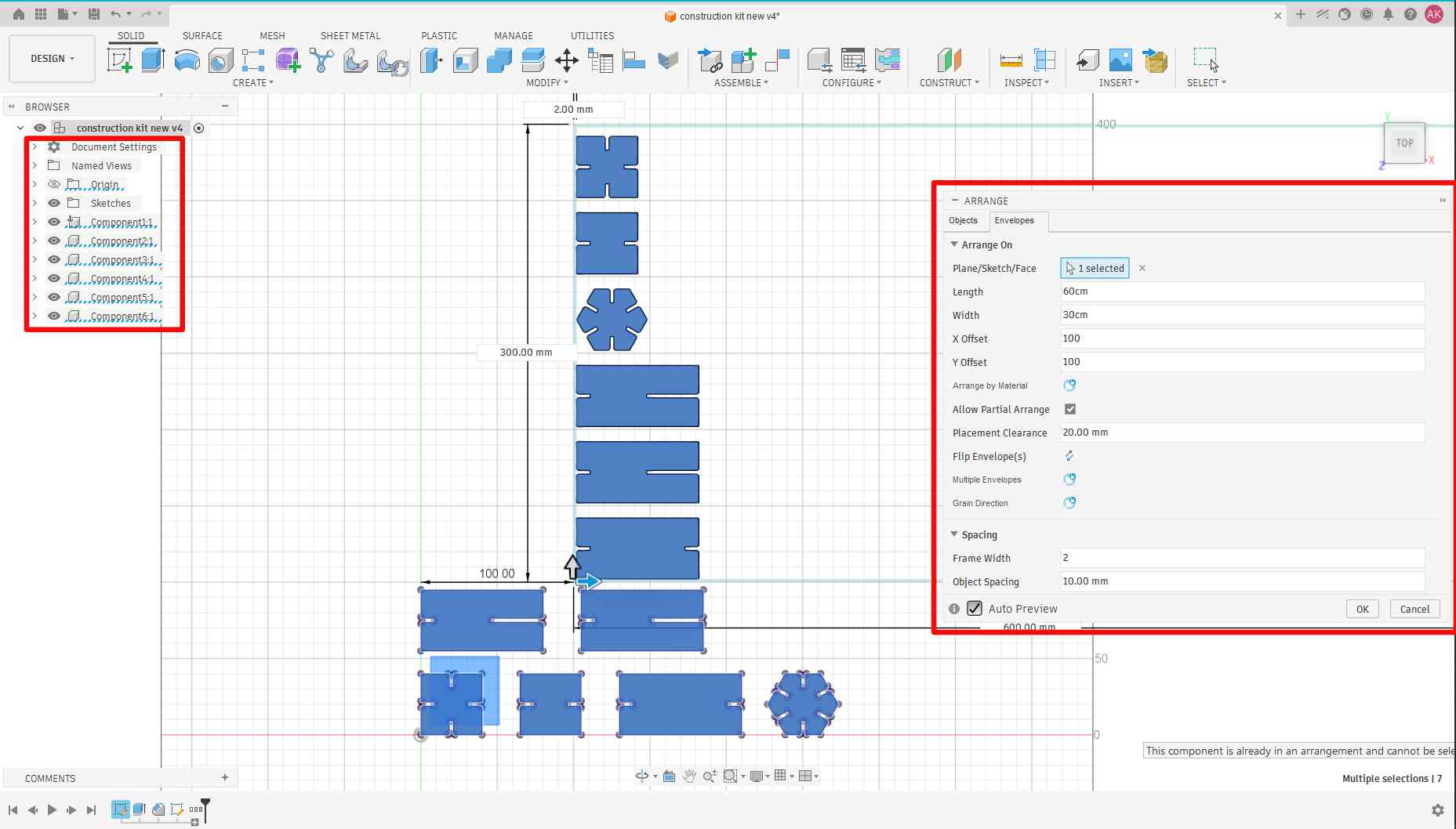
One could do this arrangement in Fusion using Modify > Arrange and then duplicate it in Inkscape.
The above image was done after that week. I didn't know to use that function then. Only later did my instructor mention that it was mandatory to know that function to pass that week.
Well, what this function does is that it uniformly arranges the components. Yeah, components and not bodies.
So, right click on bodies and select "Create Components from Bodies". It creates components. Now select Modify > Arrange, then select the faces of the components, and it arranges them into the envelope or the cardboard size we enter.
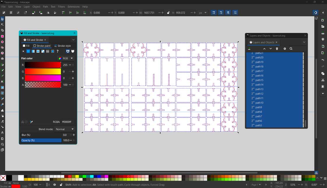
Setting Cut Lines for Laser
I selected all shapes and opened the Stroke color panel. Since the Trotec software recognizes colors to decide between cutting and engraving, I set all cut lines to:
- RGB (255, 0, 0) — pure red
- Stroke width: 0.1 mm
Again, I resized the canvas to fit the drawings using Ctrl + Shift + D. This helped visualize how the pieces would fit on the material inside the machine.
I transferred the file to the lab computer using Send Anywhere.
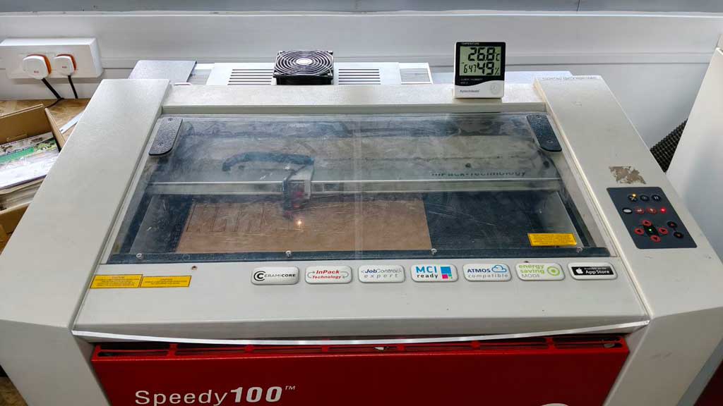
Setting Up the Trotec Speedy 100
Trotec Speedy 100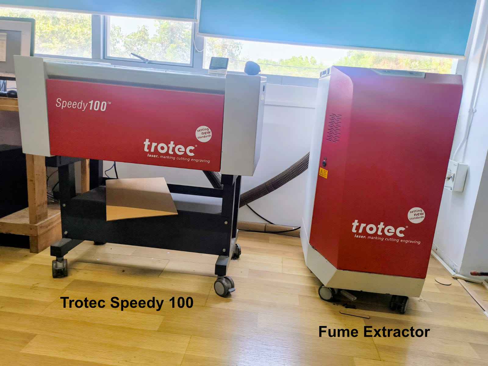 Source
I switched on both the laser machine and the exhaust system manually.
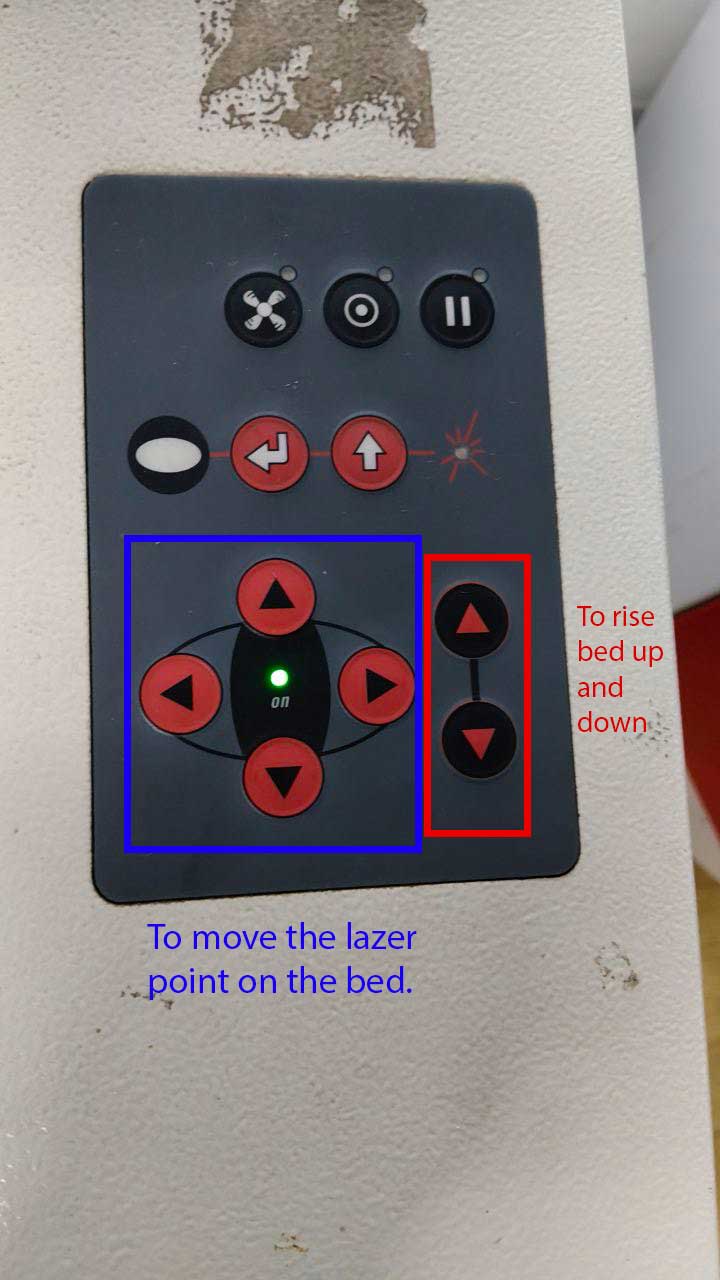
I opened the glass lid and placed the cardboard at the upper-left corner of the bed. Using the down arrow key, I lowered the bed, positioned the material properly, and then raised it again until it touched the metal stop.
This video is taken later. The material placed here is acrylic. The steps for focusing the laser are the same for both materials. However, when cutting cardboard, the cardboard material database must be selected.
I used the laser height checker to confirm focus and then removed it before cutting.
Sending the File to the Laser Cutter
In Inkscape, I pressed Ctrl + P (Print), which opened the Trotec Job Control software.
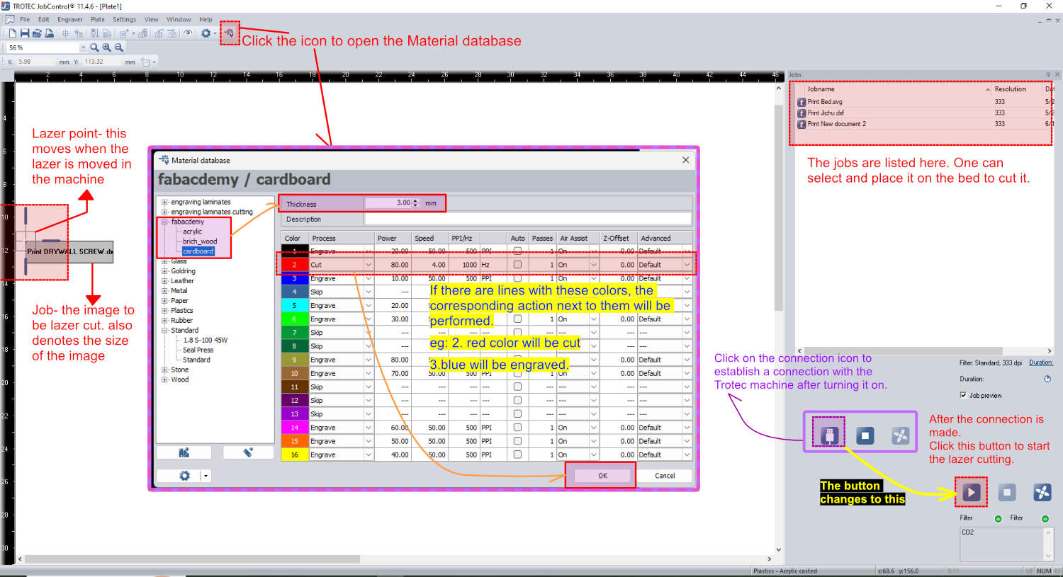
Since I could not time travel back, I edited the screenshot to show how it was done using one of the cuttings completed during a later week.
In the job window, I aligned the drawing to match the material position inside the machine. I had set my cut lines to RGB (255, 0, 0) because the Trotec JobControl software maps this specific red to the "Cut" process. To cut through the 3mm cardboard, I assigned the following material parameters to the red cut line: Power: 80%, Speed: 4%, Frequency: 1000 Hz, Passes : 1.
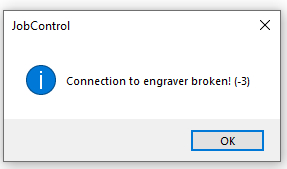
This message appears when you click the Play or Cut button. Double check that the exhaust system is turned on. This message will appear even if the exhaust is already on. Click OK
Using the arrow keys on the machine, I manually positioned the laser head over the starting point of the cut.
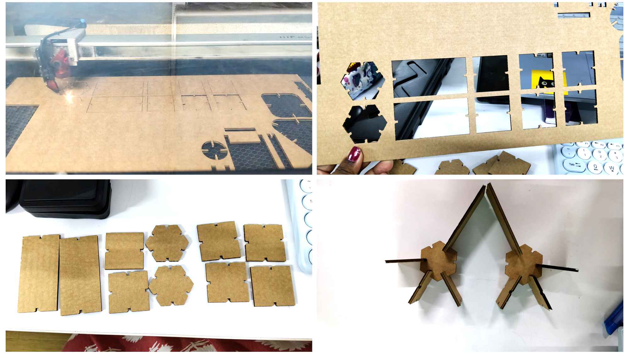
Cutting the Parts
Once everything was set, I pressed Play to begin cutting.
During the process, I noticed that some lines were overlapping, which caused the laser to cut the same path multiple times. This could potentially cause burning or fire, but fortunately, no issues occurred this time.
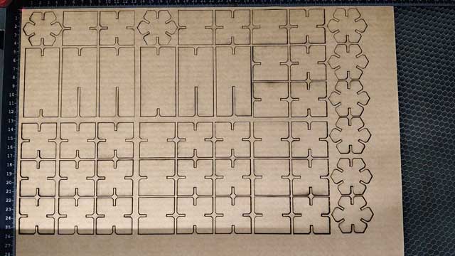
Removing and Assembling the Pieces
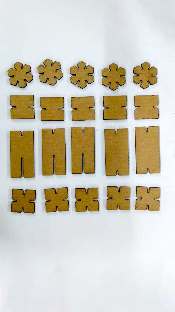
After cutting, I removed the cardboard sheet from the machine and cleaned any debris inside the laser bed.
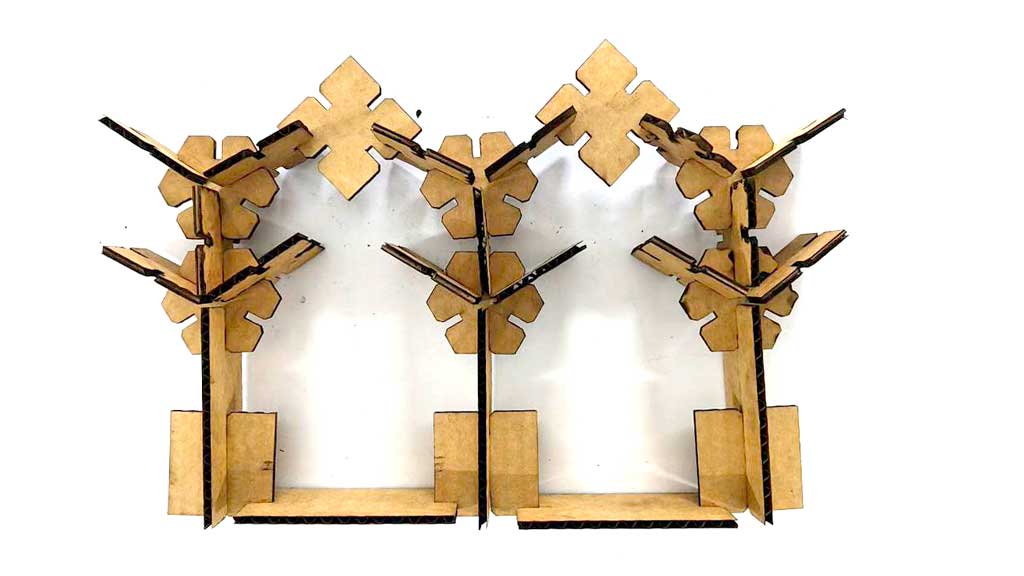
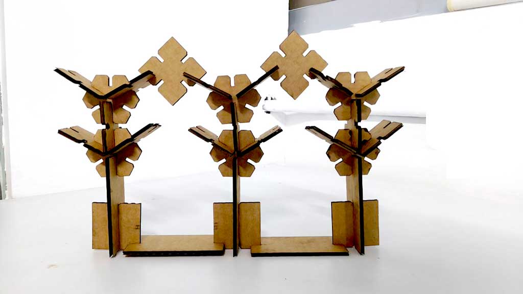
I carefully detached each piece from the sheet and assembled them by trial and error to form the final construction kit structure.
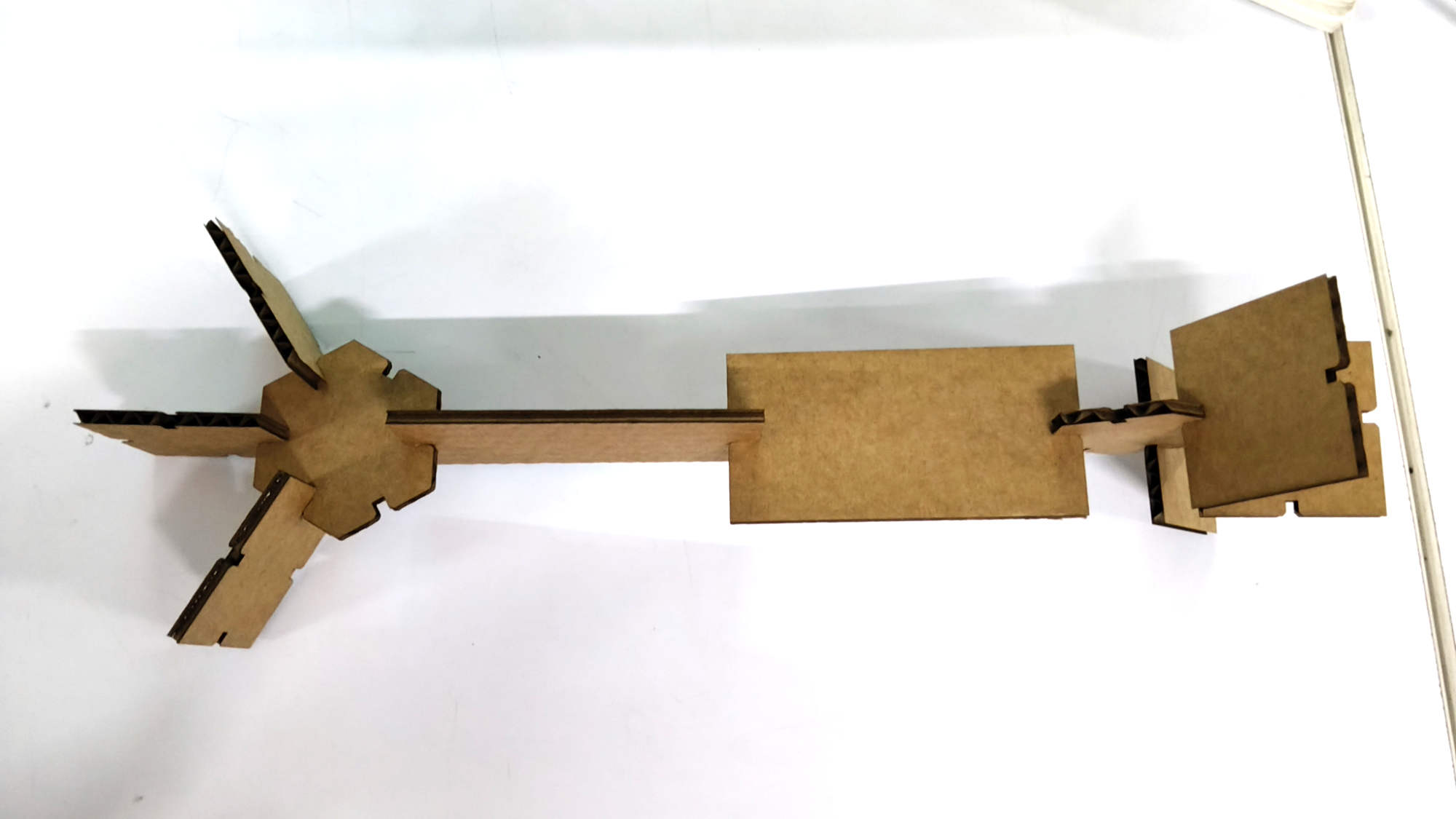
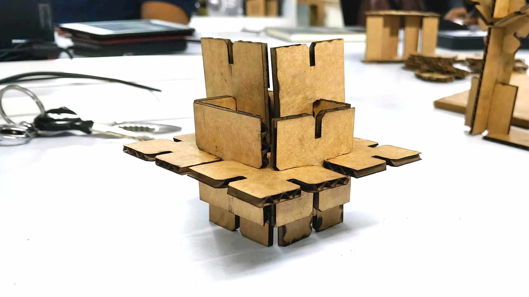
Tried different shapes