Individual Assignment
What is CNC Machining?CNC machining is an automated manufacturing process that uses computer programs to control machines. This includes machines like lathes, mills, routers, and grinders, allowing for the precise removal of material from a workpiece to create a desired shape. CNC machine operations eliminate human error and increase production speeds, ensuring high repeatability and accuracy.
How does a CNC machine work?
The CNC machining process involves several critical stages, starting from the design phase to the final finishing touches. Below is a breakdown of each step in the process:
Stage 1: Design & Programming
Stage 2: Machine Setup & Workpiece Loading
Stage 3: Machining (Cutting, Milling, Turning, etc.)
Stage 4: Finishing, Inspection & Post-Processing
Inspiration and Initial Idea
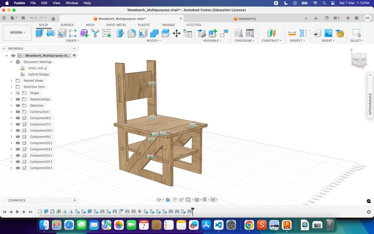
To begin the design process, I explored references on Pinterest to find ideas for a functional piece of furniture. My initial concept was centered around designing a chair. During this exploration, I came across a convertible multipurpose chair design. The concept was interesting because the chair could be folded and transformed into a ladder, making it a multifunctional piece of furniture. This adaptability and space-saving aspect made it an ideal inspiration for my project.The reference design can be found here
Designing
The design phase turned out to be the most challenging part of the process.My initial goal was to create a fully parametric design, allowing easy modification of dimensions such as material thickness, slot width, and overall size. However, the parametric setup repeatedly failed to behave as expected.
A major issue occurred with the slot width parameter. The slot width consistently became larger than the actual material thickness, even when I attempted to control it through parameters.
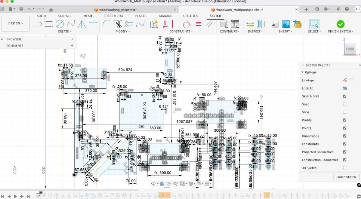 I attempted to fix this by adjusting constraints and modifying the parameter values several times.
 Despite three to four iterations of modifying the parameters, the design did not behave correctly. Every time
I updated the slot width parameter, the geometry updated incorrectly, resulting in misaligned or oversized slots.
Despite three to four iterations of modifying the parameters, the design did not behave correctly. Every time
I updated the slot width parameter, the geometry updated incorrectly, resulting in misaligned or oversized slots.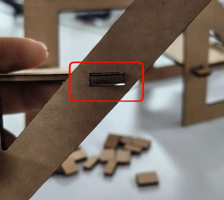 At this point, my instructor reviewed the file and suggested that instead of continuing to troubleshoot the existing design,
I should start with a completely fresh sketch.
At this point, my instructor reviewed the file and suggested that instead of continuing to troubleshoot the existing design,
I should start with a completely fresh sketch.
Redesign Approach
Following this advice, I decided to redesign the model from scratch using a different workflow.In my previous attempt, the entire structure was drawn in 2D sketches and then extruded into a 3D model.
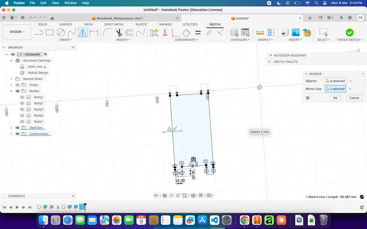
For the new design, I changed my approach:
- I began by creating two basic structural elements in a 2D sketch.
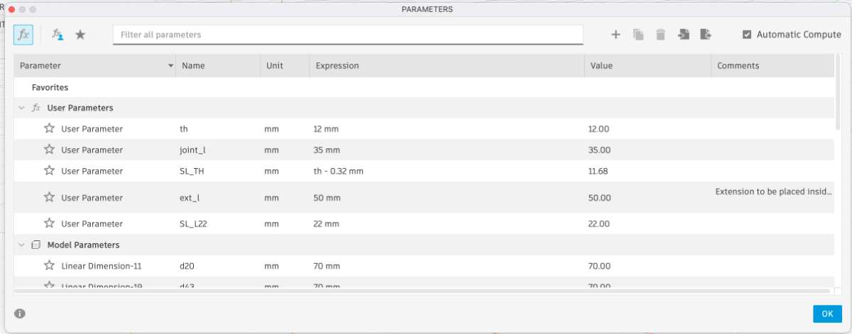
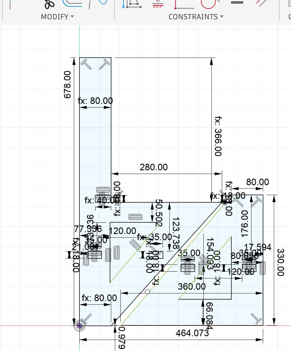 To make the construction kit adaptable to different materials and fit conditions, I created user parameters in Fusion 360.
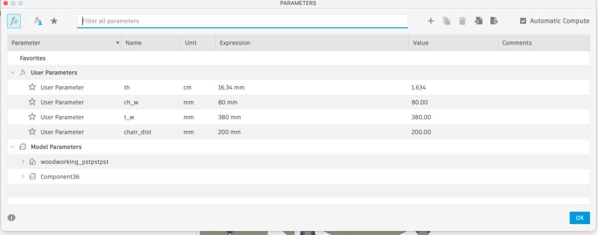 This parametric setup allowed me to quickly adapt the design to different materials without redrawing the geometry.
- These base components were extruded into 3D geometry.
 - From the extruded bodies, I then constructed the remaining features directly in the 3D workspace.
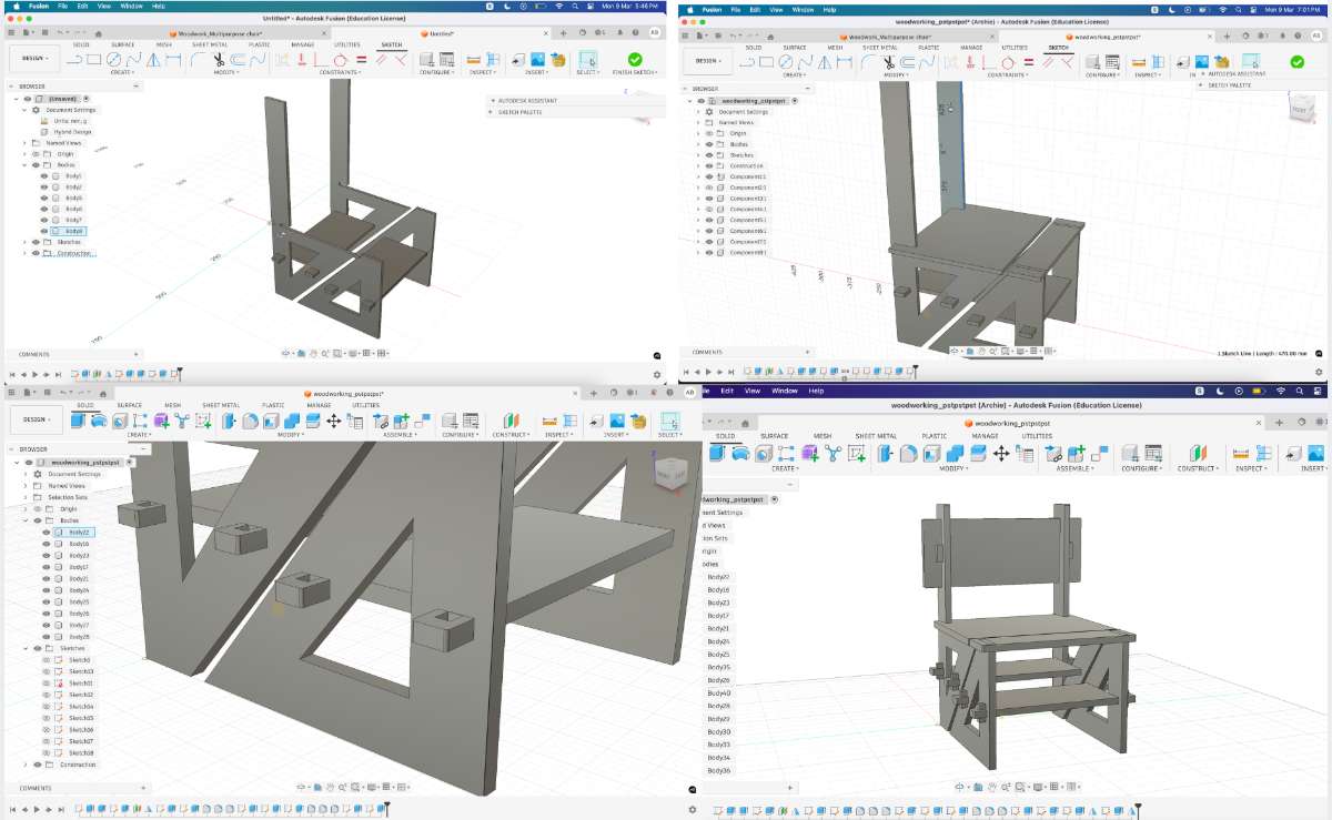
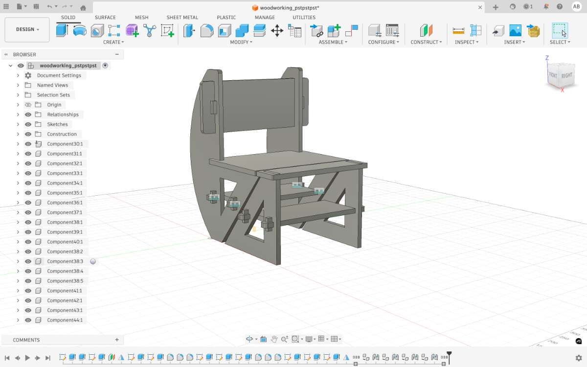 Using this method, I was able to complete the entire design in less than three hours,
which was significantly faster compared to the earlier attempts.
Using this method, I was able to complete the entire design in less than three hours,
which was significantly faster compared to the earlier attempts.Another advantage of this approach was that the parametric relationships worked more reliably.
When I adjusted parameters such as width or length, the model updated correctly, and the overall proportions remained consistent.
This felt like a major milestone in my design process, especially after the earlier struggles with parametric constraints.
Scaling the Design for Cardboard Prototyping
The original design was created based on the actual dimensions required for fabrication in plywood. However, before moving to the final material, a scaled prototype needed to be produced using cardboard in order to test the structure and slot fitting.
Since the cardboard sheet used for prototyping had a material thickness of 3 mm, the design had to be scaled down proportionally.
Exporting the Design To prepare the file for laser cutting, the following steps were performed:
I projected the sketch by selecting the required faces and then pressed "Ctrl + P" from the 3D model to obtain the flat geometry required for cutting.
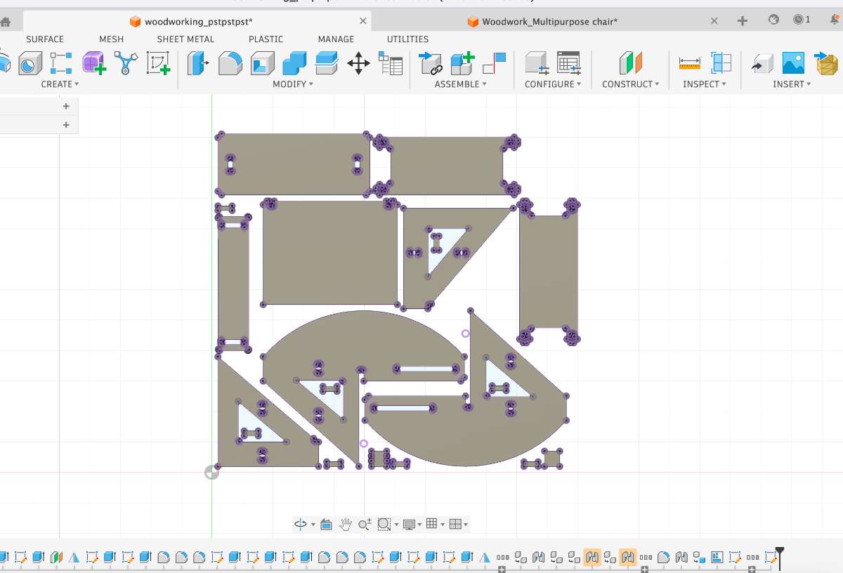 The exported DXF file was then imported into DeepNest for nesting. DeepNest automatically arranged the parts to minimize material waste and optimize sheet utilization. Once the nesting was complete, I exported the layout as an SVG file and verified all dimensions in Inkscape before sending it to the laser cutter.
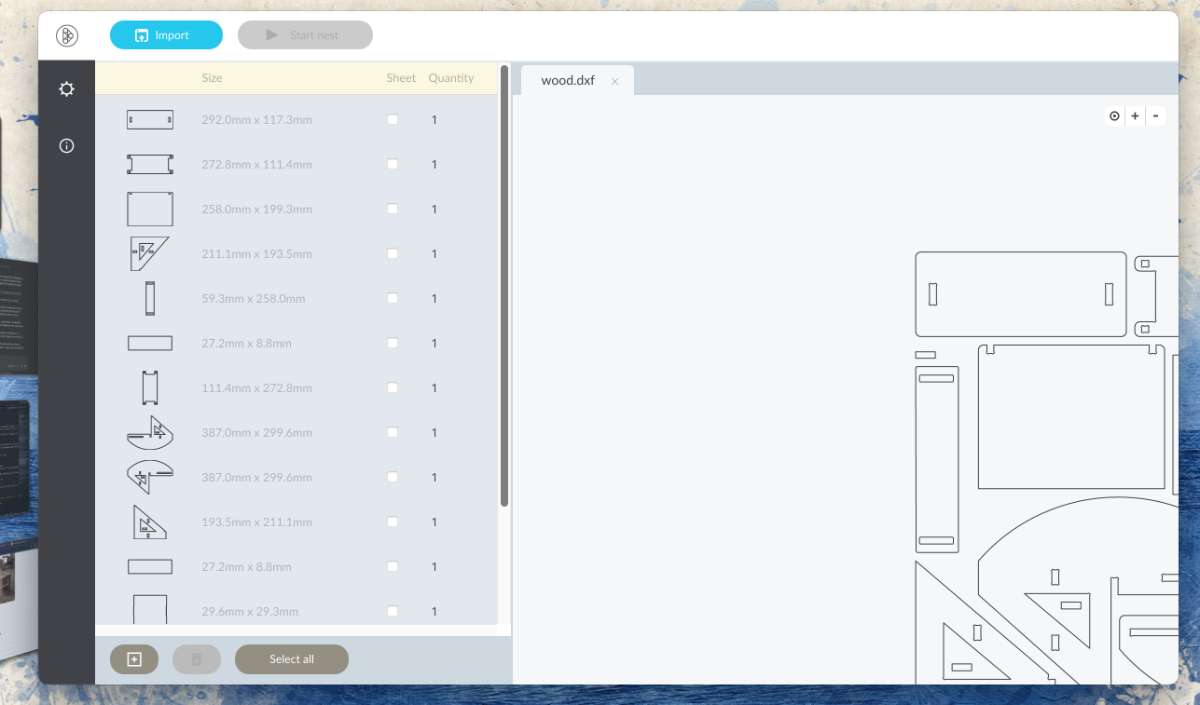 (click for settings to access DeepNest)
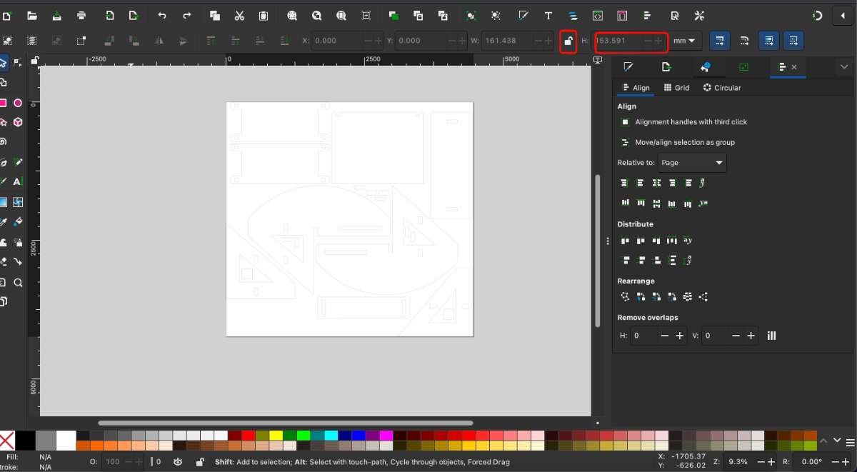
The DXF file was opened in Inkscape for further adjustments and scaling.
(click for settings to access DeepNest)
The DXF file was opened in Inkscape for further adjustments and scaling.Why Manual Scaling Was Required
Although the design itself was fully parametric inside Fusion 360, the scaling issue occurred during the file transfer workflow rather than the design stage.
The geometry exported from Fusion 360 retained its correct dimensions. However, DeepNest was configured with inconsistent units (points instead of millimeters), causing the imported DXF to be interpreted at the wrong scale. As a result, the design needed manual rescaling after import
 Since the design was originally created at a larger size, I needed to calculate a scale ratio to fit the cardboard
prototype.
Since the design was originally created at a larger size, I needed to calculate a scale ratio to fit the cardboard
prototype.The workflow I followed was:
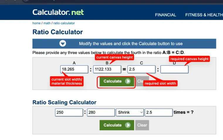 use this link
to access the ratio calculator.
use this link
to access the ratio calculator.
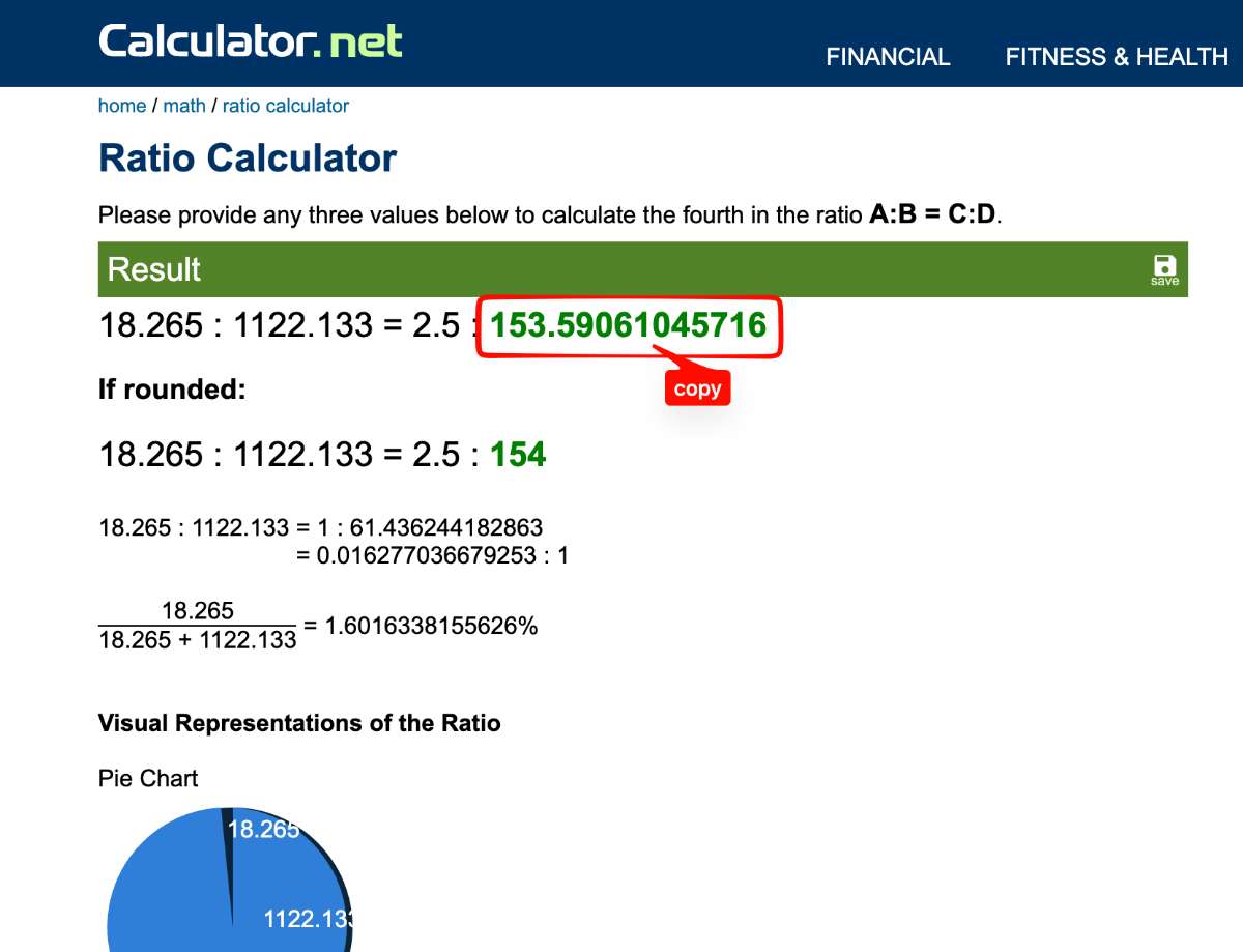
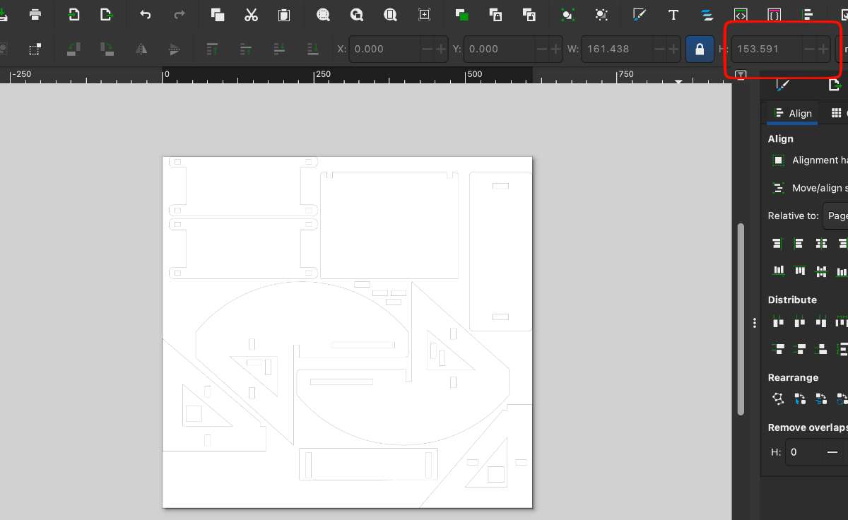 Using the calculated ratio, I scaled the design proportionally.
The resized vector geometry was then copied back into Inkscape and placed on the working page.
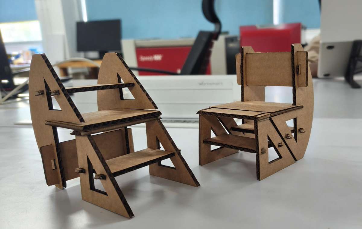
Then i cut it in cardboard -
Final Result :
 After finalizing the model, I measured the plywood sheet that would be used for fabricating the furniture.
To ensure accuracy, I measured the material thickness
at multiple points on the same side of the sheet and calculated the average thickness, which came out to 16.34 mm
After finalizing the model, I measured the plywood sheet that would be used for fabricating the furniture.
To ensure accuracy, I measured the material thickness
at multiple points on the same side of the sheet and calculated the average thickness, which came out to 16.34 mmOnce the correct material thickness was determined, I rescaled the furniture design to the required dimensions. I then added dog-bone fillets to the internal corners to compensate
for the round cutting bit used during machining, ensuring that the joints would fit properly during assembly.
To create these dogbones, I installed a plugin from the Autodesk Fusion App Store called Nifty Dogbone for Autodesk Fusion. After installation, the tool appeared under the Modify menu as Nifty Dogbone.
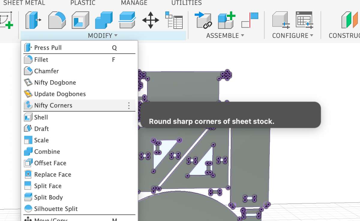
Nifty Dog Bones: CNC router bits are round, so they can't cut sharp inside corners —
they always leave a small curve. This is a problem when two pieces need to fit together, since the mating piece has sharp outside corners that won't seat into the rounded recess. Dog bones are small circular cutouts added at inside corners so the bit fully clears the corner, letting mating pieces fit flush. The circle diameter matches your cutting tool.
After which you can arrange, project and export as a DXF file,ready for print.
V carve SettingsFor setting up the CNC toolpaths, We used VCarve Pro – ShopBot Edition, which is the CAD/CAM software that works with the ShopBot machines at our lab. I started by opening VCarve and creating a new file. The job size was set to match the plywood sheet I was using — 8 ft × 4 ft — and the material thickness was 16.34 mm, which I got from measuring the sheet earlier. Once that was done, the workspace was ready.
/Screenshot_2.jpg) To bring in the design, I went to File → Import Vectors and loaded the DXF file I had exported from Fusion 360.
To bring in the design, I went to File → Import Vectors and loaded the DXF file I had exported from Fusion 360.
/Screenshot_3.jpg)
/Screenshot_4.jpg)
/Screenshot_5.jpg) The plywood sheet needs to be physically secured to the machine bed. The ShopBot has a sacrificial layer already on
the bed, and the sheet sits on top of that.
The plywood sheet needs to be physically secured to the machine bed. The ShopBot has a sacrificial layer already on
the bed, and the sheet sits on top of that. Screws go through the sheet into the sacrificial layer to hold everything in place while cutting.
The tricky part is making sure the screws aren't placed anywhere the tool will travel — if the end mill hits a screw, it'll break. So I drew small 6 mm diameter circles from the left toolbar in areas that would be safe (away from any toolpaths), and created a drilling toolpath for them.
/Screenshot_12.jpg)
/Screenshot_13.jpg) This is how the 3D Preview of our Drilling toolpath looks like:
This is how the 3D Preview of our Drilling toolpath looks like:
/Screenshot_14.jpg)
/Screenshot_8.jpg)
/Screenshot_9.jpg)
/Screenshot_10.jpg) For the slot features, I went to the right toolbar -> a Pocket Toolpath set to conventional — this makes sure the tool
runs along the inner edge of the vector, keeping the slot dimensions accurate.
The tool I used was a 6 mm single-flute end mill, with Cut depth 18 mm.
For the slot features, I went to the right toolbar -> a Pocket Toolpath set to conventional — this makes sure the tool
runs along the inner edge of the vector, keeping the slot dimensions accurate.
The tool I used was a 6 mm single-flute end mill, with Cut depth 18 mm.
/Screenshot_29.jpg)
The last operation was cutting out the outer edges of each part, got o Profile Toolpath -> Outside Cut so the tool stays on the outer side of the line and the part comes out the right size.
/Screenshot_21.jpg) VCarve did throw a warning saying the cut depth exceeds material thickness — but that was intentional, so I accepted it and moved on.
VCarve did throw a warning saying the cut depth exceeds material thickness — but that was intentional, so I accepted it and moved on./Screenshot_18.jpg) This is the 3D toolpath view:
This is the 3D toolpath view: /Screenshot_23.jpg) Then I added holding tabs to some of the larger internal cutouts to stop pieces from moving around mid-cut.
Then I added holding tabs to some of the larger internal cutouts to stop pieces from moving around mid-cut.
/Screenshot_26.jpg)
/Screenshot_27.jpg) I saved the toolpaths as two separate ShopBot Part Files (.SBP):
I saved the toolpaths as two separate ShopBot Part Files (.SBP):File 1 — the drilling operation only (for marking screw positions)
File 2 — the slot cutting + outer profile cuts
/Screenshot_25.jpg) Keeping them separate so that I can run the drill marks first, physically screw down the sheet, and then run the actual cuts
without any risk of the tool running into a screw.
Keeping them separate so that I can run the drill marks first, physically screw down the sheet, and then run the actual cuts
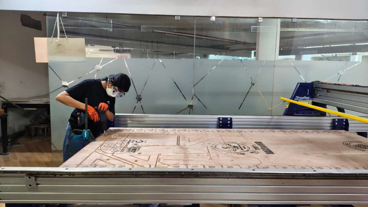
without any risk of the tool running into a screw.ShopBot CNC Router
The ShopBot CNC Router is a computer-controlled subtractive manufacturing machine used for cutting, carving, drilling, and shaping sheet materials such as plywood, MDF, acrylic, and composites. It operates by moving a rotating cutting tool along the X, Y, and Z axes according to toolpaths generated from CAD/CAM software./load.jpg) I loaded the plywood sheet onto the Shobot. Then I clamp the workpieces onto the bed with the help of clamps
and screws at the edge of the bed.
I loaded the plywood sheet onto the Shobot. Then I clamp the workpieces onto the bed with the help of clamps
and screws at the edge of the bed.The tool i used was a 6 mm single-flute end mill, with the feed rate set to 1200 mm/min. The start depth was set to 0 mm, since the tool begins cutting from the surface of the material. The cut depth was set to 13 mm, which is slightly deeper than the actual material thickness of 12.4 mm. This ensures the tool cuts completely through the plywood and slightly into the sacrificial layer, preventing incomplete cuts caused by small thickness variations in the material.
Then I clicked 'Start' and ran on the spindle by clicking 'Ok' in the dialogue box. Then we have to wait for a few seconds so that RPM of the spindle stabilises. Then I click 'Ok' and the machine starts routing the workpiece according to the design provided.
/Screenshot_36.jpg) Then I drill screws into each of these holes
Then I moved the tool to one end of the machine and I took X and Y offset. For the Z offset we used a touchplate.
Then I drill screws into each of these holes
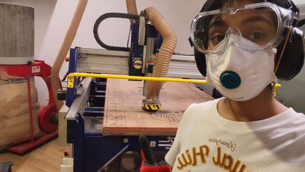
Then I moved the tool to one end of the machine and I took X and Y offset. For the Z offset we used a touchplate.Now I wait for the machine to finish cutting all the pieces. It is important to wear all the required safety equipment, including gloves and safety goggles. In addition, safety headphones must be worn because the machine produces a high level of noise during the cutting process.
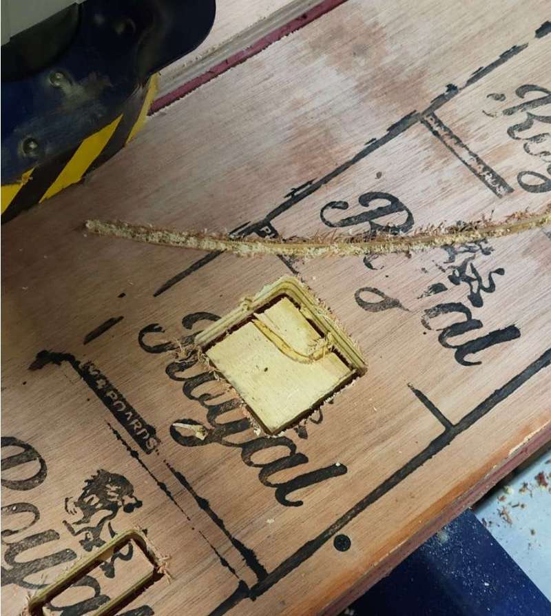
During the milling process two pieces broke, mostly due to poor material.
 Once the cutting is done, we have to unscrew the sheet from the bed.
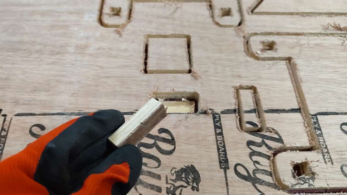
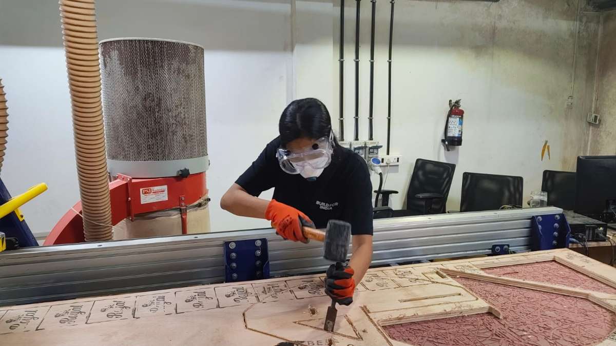
 Then cut the tabs using the chisel and mallet.
 afterwards removes the sheet from the bed and did some post processing.
Then assembled the parts together.
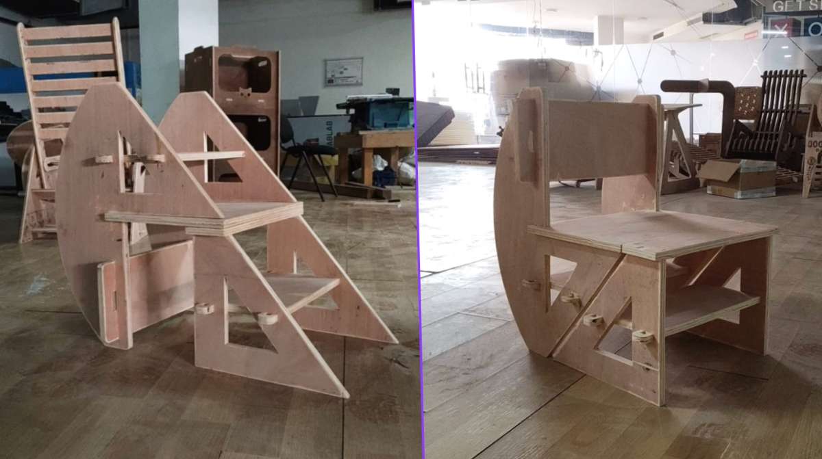 (HERO SHOT)
Conclusion
Challenges Faced-Initially, the nested DXF file was imported into DeepNest with incorrect unit settings, causing the parts to be scaled down unexpectedly.
-Several test cuts were required before achieving a satisfactory press-fit tolerance.
-Minor dimensional variations in the cardboard thickness affected the consistency of some joints.
-The wood kept chipping during cutting due to poor quality.
-During assembly, a few slots were tighter than expected and required slight manual adjustment before insertion.
-Aligning multiple components during large assemblies required careful sequencing to avoid forcing joints and damaging the cardboard.
These challenges helped me better understand the relationship between kerf compensation, material properties, and assembly tolerances.