Aura smart hair oil Dispenser
Project Planning & Design
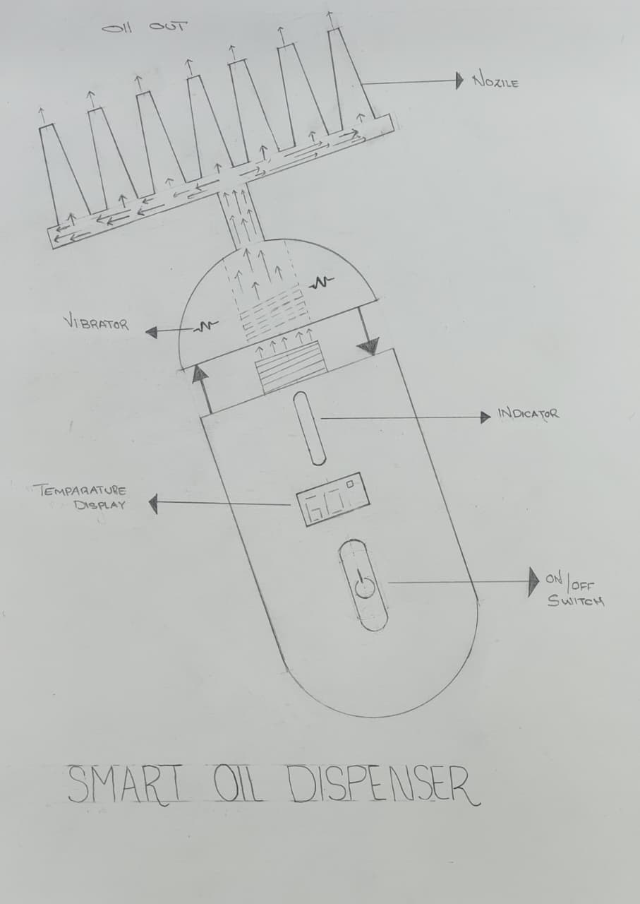
During Week 01 (Principles and Practices), I sketched the initial concept and defined the project requirements. The sketch below shows my initial hand-drawn concept:
Abstract
The Smart Hair Oil Dispenser is an innovative personal care device designed to improve hair nourishment and scalp health through controlled oil heating, precise dispensing, and therapeutic massage. The system incorporates a 20 ml aluminum chamber that enables efficient heating and cooling of hair oil, with a maximum operating temperature of 60 °C. Controlled heating enhances oil absorption, supports faster hair growth, and helps maintain scalp protection without causing thermal damage.
The device features a precision nozzle that ensures smooth and direct oil delivery to the hair roots, minimizing wastage and improving effectiveness. An integrated vibration motor at the tip provides gentle scalp massage, promoting better blood circulation and enhanced nutrient penetration. The body is ergonomically curved to prevent oil staining and to ensure comfortable handling during use.
For safety and reliability, the dispenser is equipped with wireless charging technology, eliminating the risk of sparks in oil-exposed environments. A built-in rechargeable battery provides backup power for uninterrupted operation. By combining thermal control, targeted oil application, and massage therapy in a compact and safe design, the Smart Hair Oil Dispenser offers an efficient and user-friendly solution for modern hair care.
Who Will Use This Project?
The Smart Hair Oil Dispenser is designed for individuals who regularly apply hair oil and want a more efficient, hygienic, and effective way to nourish their hair and scalp. The primary target users include:
- Home users – People who apply hair oil as part of their daily or weekly hair care routine and want controlled heating and precise application.
- People with hair/scalp issues – Individuals dealing with hair fall, dry scalp, or slow hair growth who can benefit from warm oil therapy and scalp massage.
- Elderly users – Older adults who may have difficulty applying oil manually and need an easy-to-use dispenser.
- Beauty salons and spas – Professional establishments offering hair treatments that require heated oil application.
- Caregivers – Those who assist others with hair care, as the device simplifies the oil application process.
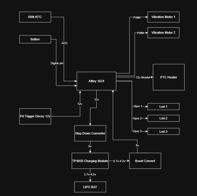
Functional Block Diagram
Userflow Diagram
Machining the Aluminum Block
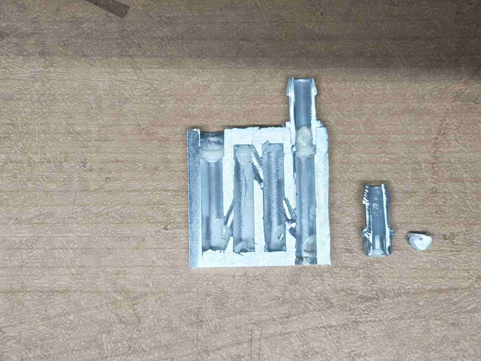
To understand the internal structure of the aluminum block, I machined the top layer using the TRAK DPM RX2 CNC Milling Machine. After removing the top surface, I was able to see the internal cooling channels inside the block. This helped me understand the coolant flow path and the internal design before using the block in my final project.
this is the milled aluminum block looking at the internal cooling channels
Silicone Filling Test
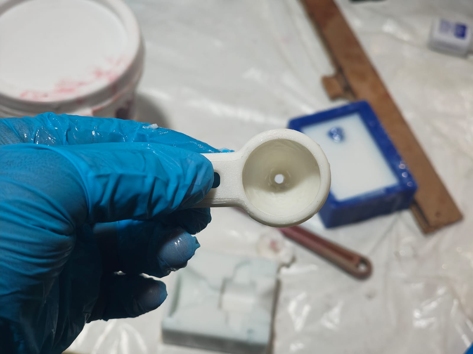
I printed a small cone-shaped part to test the inside. My first idea was to fill the inside with silicone. I thought the silicone would stop the mold from changing shape and keep the oil chamber clean and hygienic.
After testing, I found that this idea did not work as I expected. The silicone did not give the result I wanted, so I decided not to use this method and looked for another solution.
Oil Flow Test
I tested the aluminum block by closing one hole with a cap. I wanted to check if air would get trapped inside the block while the oil was flowing.
This test helped me understand how the oil moves inside the block and whether trapped air could affect the oil flow. I used the results to improve the design.
Oil Volume Capacity Test
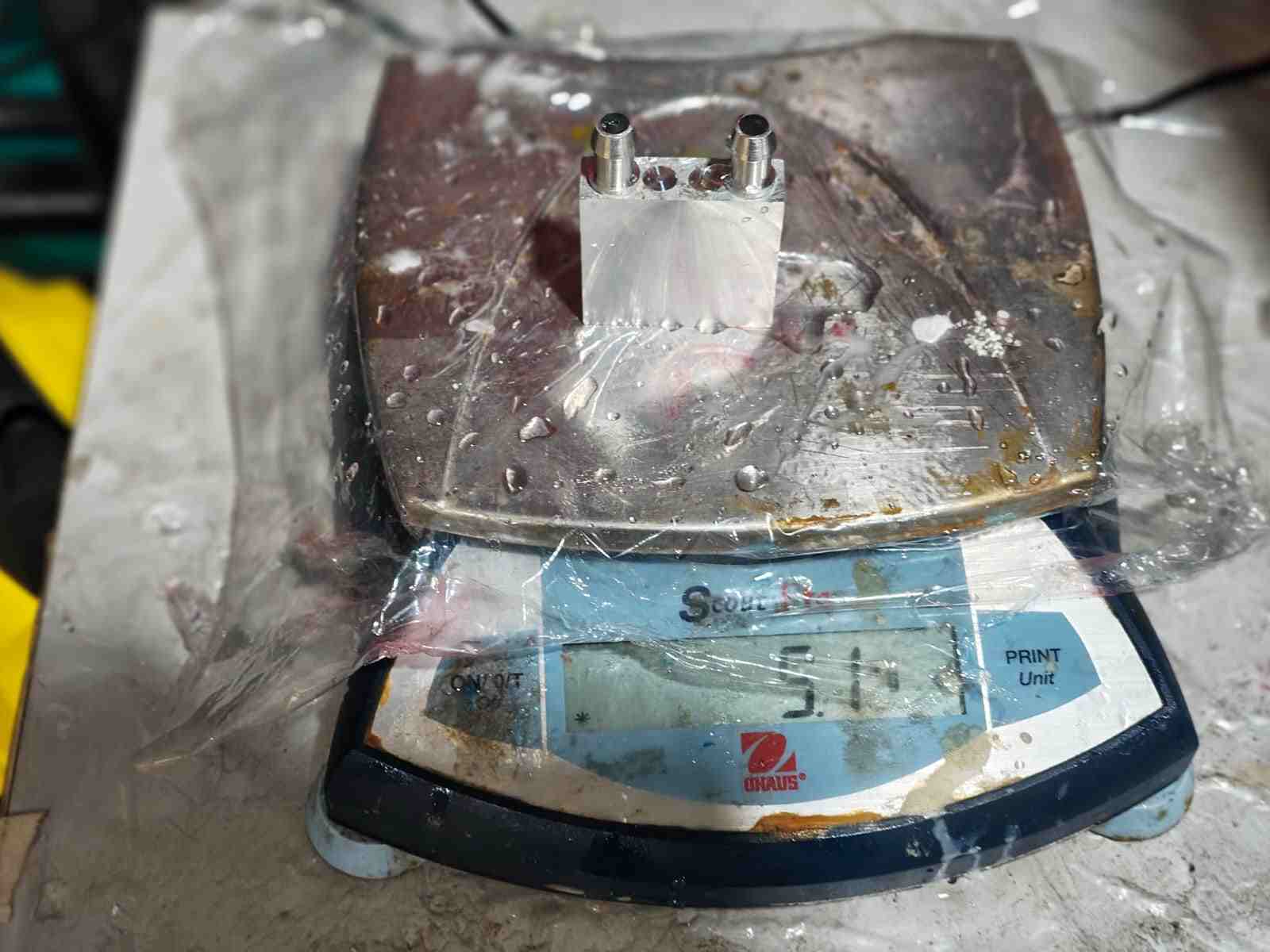
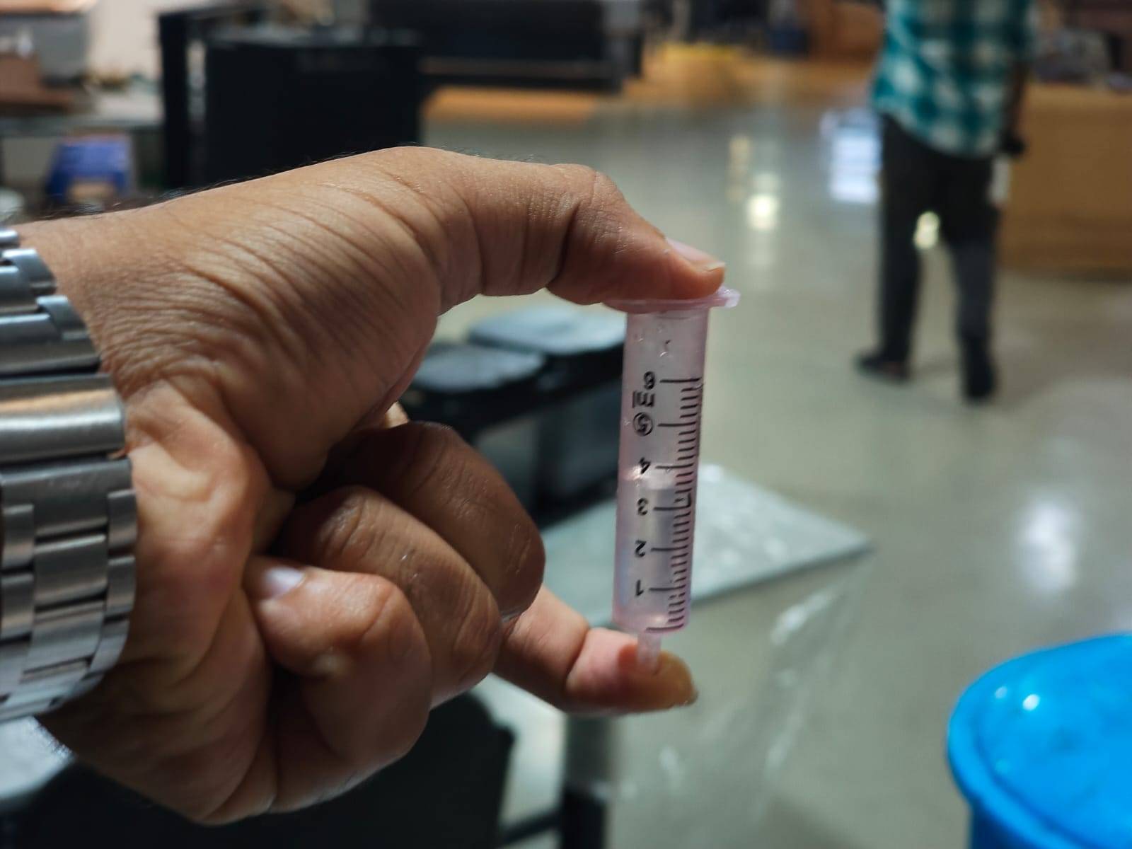
I tested the aluminum block to check how much oil it can hold. I filled the block with oil using a syringe and measured the amount of oil stored inside.
This test helped me know the oil capacity of the block. The result showed that the block can store about 5 ml of oil.
Output Device Test
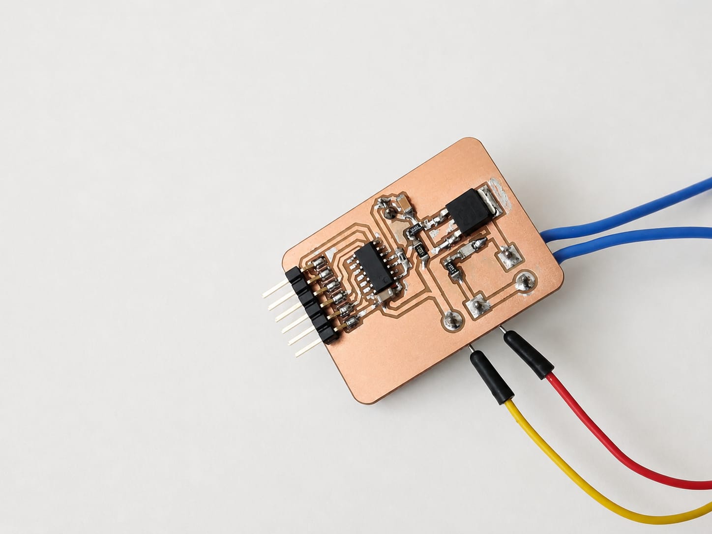
During Week 10 - Output Devices, I tested a PCB with a 100K thermistor and a PTC heater.
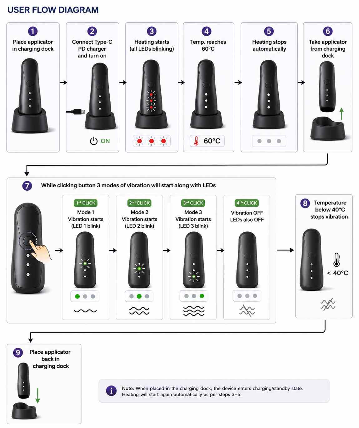
I programmed the system to stop heating when the temperature reached 60°C. After that, the temperature slowly started to go down.
When the temperature dropped below 40°C, the heater automatically started heating again. This helped keep the temperature within the required range.
I used this test as a reference for my final project. For more details about the PCB design, circuit, and testing, please visit my Week 10 documentation.
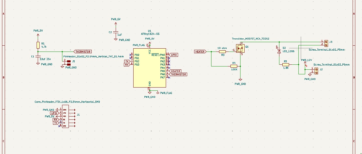
This is the output PCB that I made for the heating system.
Final Temperature Test
After completing the PCB, I tested the heating system using a thermal camera. The thermal camera helped me check the temperature of the PTC heater in real time.
During the test, the heater reached the target temperature of 60°C. When the temperature dropped below 40°C, the heater automatically started heating again. The thermal camera confirmed that the temperature control was working correctly.
The video below shows the final temperature testing of the heating system using a thermal camera.
Designing and Assembling the Comb Applicator
Oil Applicator - Section View
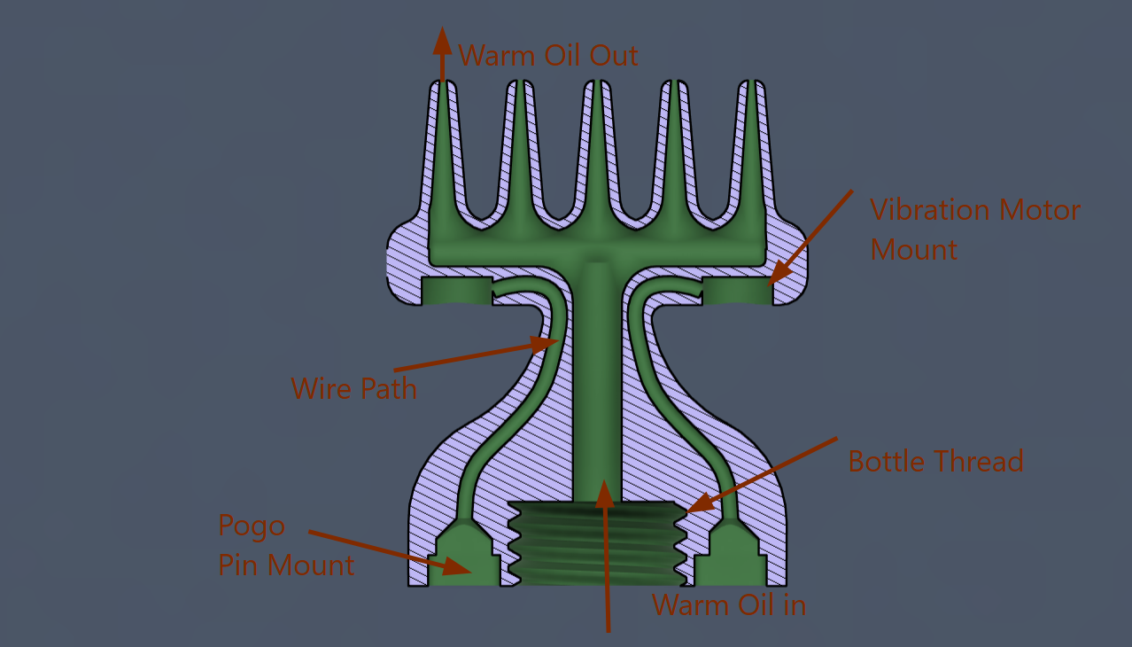
The image below shows the section view of the oil applicator used in my final project. This design helped me understand the internal structure before making the final model.
The applicator has a warm oil inlet at the bottom and a warm oil outlet at the top. Warm oil flows through the center channel and comes out through the applicator teeth for smooth oil application.
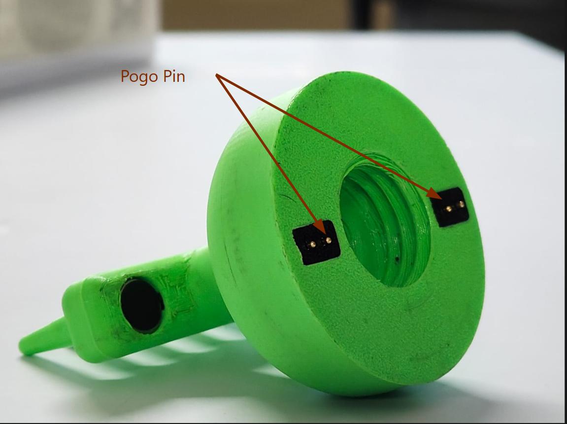
The design also includes a vibration motor mount, wire path, pogo pin mount, and a bottle thread. These features help assemble all the parts neatly and make the applicator easy to use.
First Working Prototype
This was the first working model of the oil applicator. I tested the oil flow.
The test was successful.oil flowed smoothly through all the small holes at the end of the applicator. This confirmed that the internal oil path was working as expected.
The video below shows the first successful test of the oil applicator with proper oil flow through the holes.
Adding the Copper Wire During 3D Printing
After confirming that all the dimensions were correct, I added a copper enamel-coated wire inside the comb applicator.
To do this, I used the Pause feature in Bambu Studio. The printer stopped at the required layer, and I placed the wire inside the print.
The wire runs from the bottom of the applicator to the vibration motor housing. I tied the wire in place and then resumed the print. This allowed the wire to be safely embedded inside the printed part without any extra assembly.
Using twiser I placed the wire inside the print.
After placing the wire, I resumed the print.
This was the final result of embedding the copper wire inside the 3D-printed applicator.
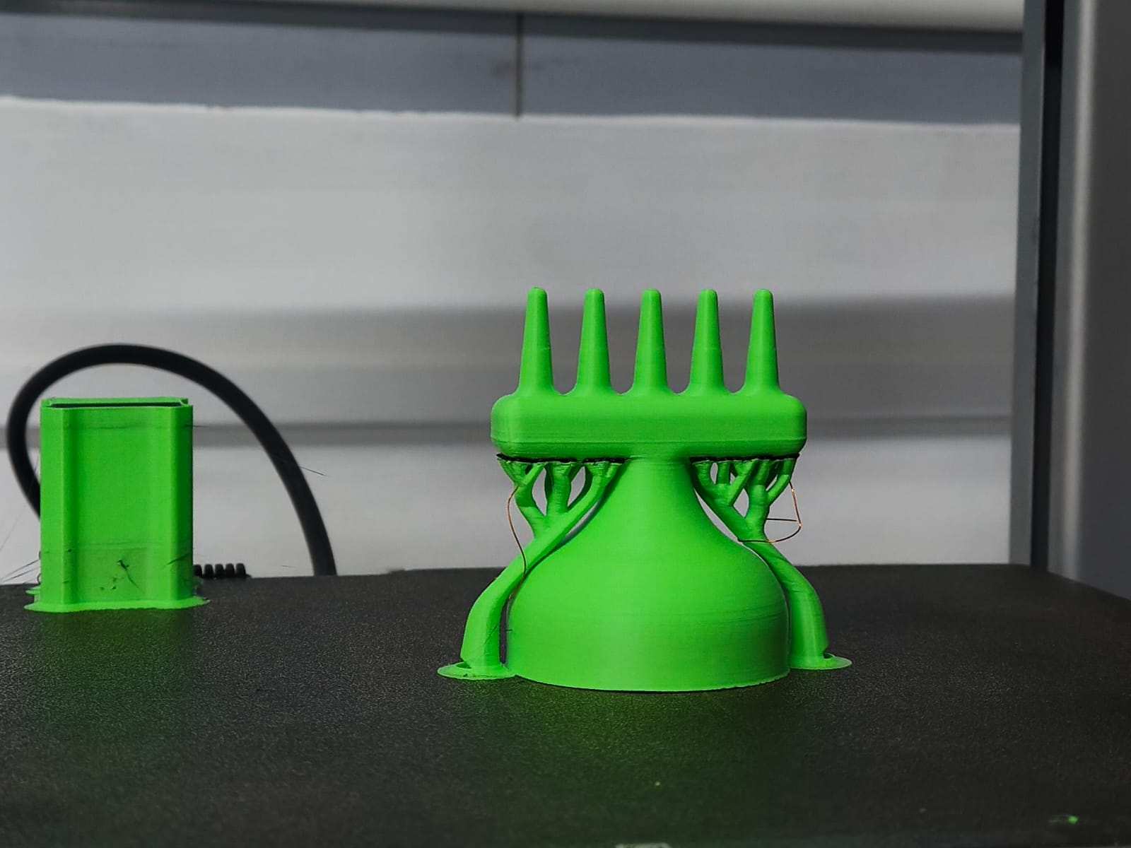
after 3d printing use copper wire through vibration motor wire holes using a tweezers.
next step is very important and requires careful handling solder enamel-coated wire to the vibration motor then solder both ends of vibration motor and the copper wire then pull back copper wire then the vibration motor will be go and set in place
this is the result
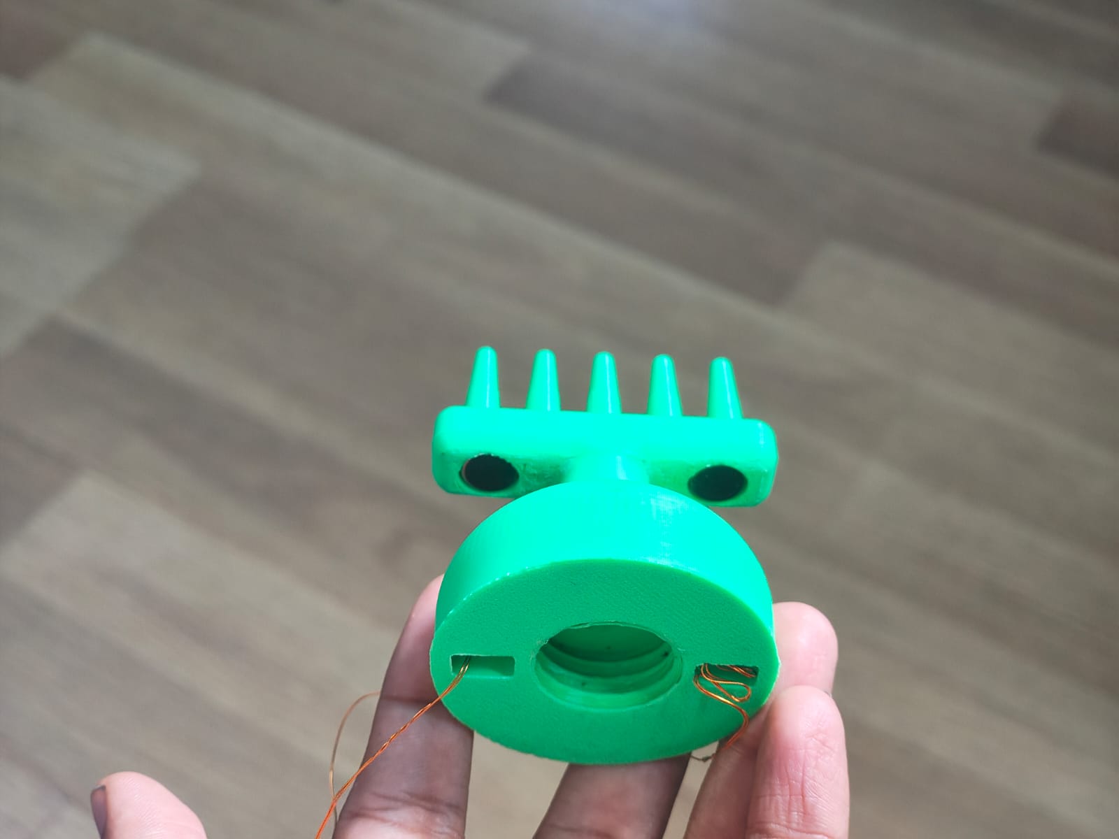
next we need to cut extra wire thwn we need to solder pogo pin to pcb then we need to solder with vibration motor actualy I forgot to take images of that process and fix with 3d printed support
Final pcb
this is the final product pcb most of components are in smd designed and soldered .some componentes like tp4056 module,tp4056 i used direct board mounting
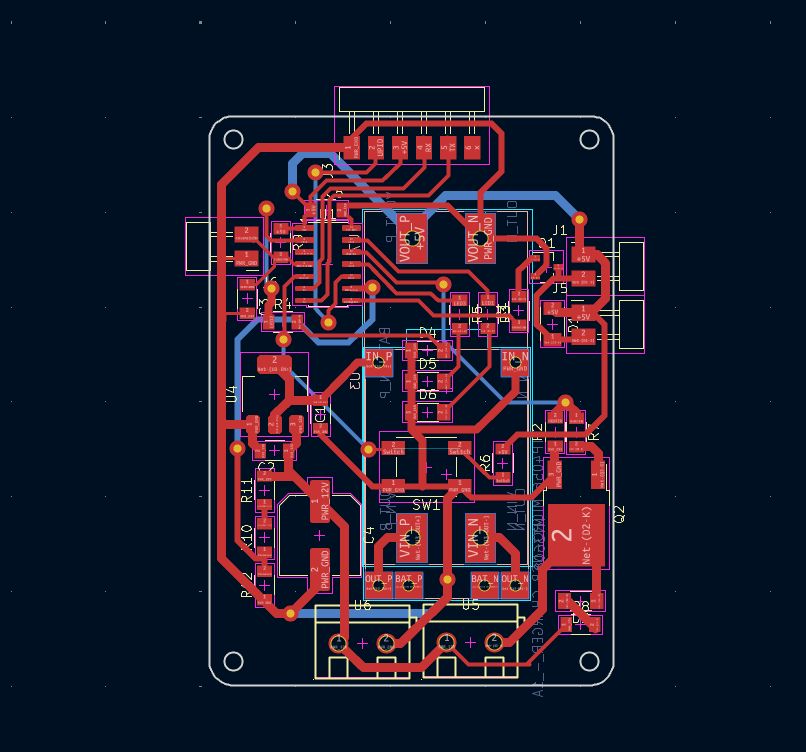
this is the final project PCB Layout Design
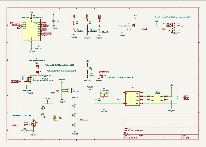
This is the final PCB 3D model in KiCad. It includes all the circuits required for my final project, such as the ATtiny1624, heater control, temperature sensing, vibration motor control, charging circuit, and connectors.
The TP4056 module does not have the correct 3D model in the KiCad library. So, I only added its footprint to complete the PCB layout.
The vibration motor also does not have a suitable footprint or 3D model in the KiCad library. For reference, I used a pin header footprint to show the motor connection on the PCB.
After completing the layout, I checked all the connections and prepared the PCB for milling and assembly.
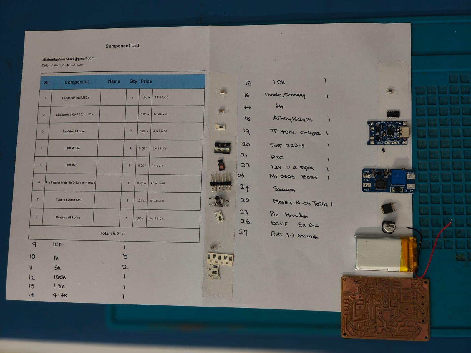
component list
Timelapse of the PCB assembly process
Finally programmed and tested. Working properly.
I forgot to take original photos after soldering
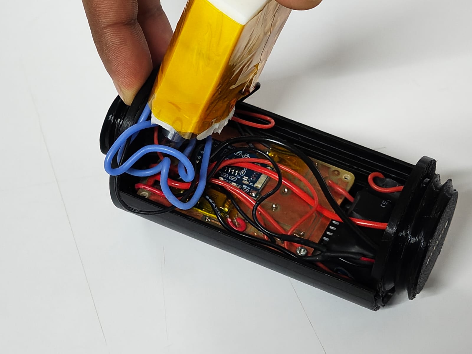
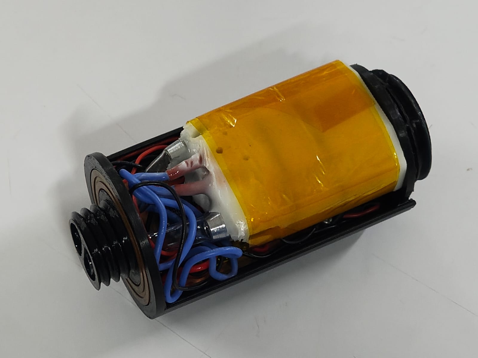
This is how it looks after placing everything in enclosure .here you can see silicone wires ididnt cut excessive length
Heating Block Fabrication Using Silicone Casting
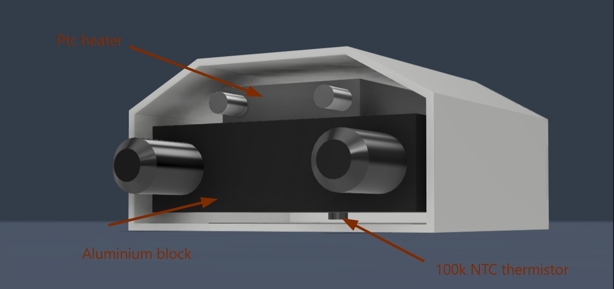
The CAD model bellow illustrates the heating block assembly used for the silicone casting process. A 2 mm hole was drilled into the aluminum block to accommodate a 100k NTC thermistor. The thermistor was inserted into the hole using thermal paste to ensure accurate temperature sensing and efficient heat transfer.
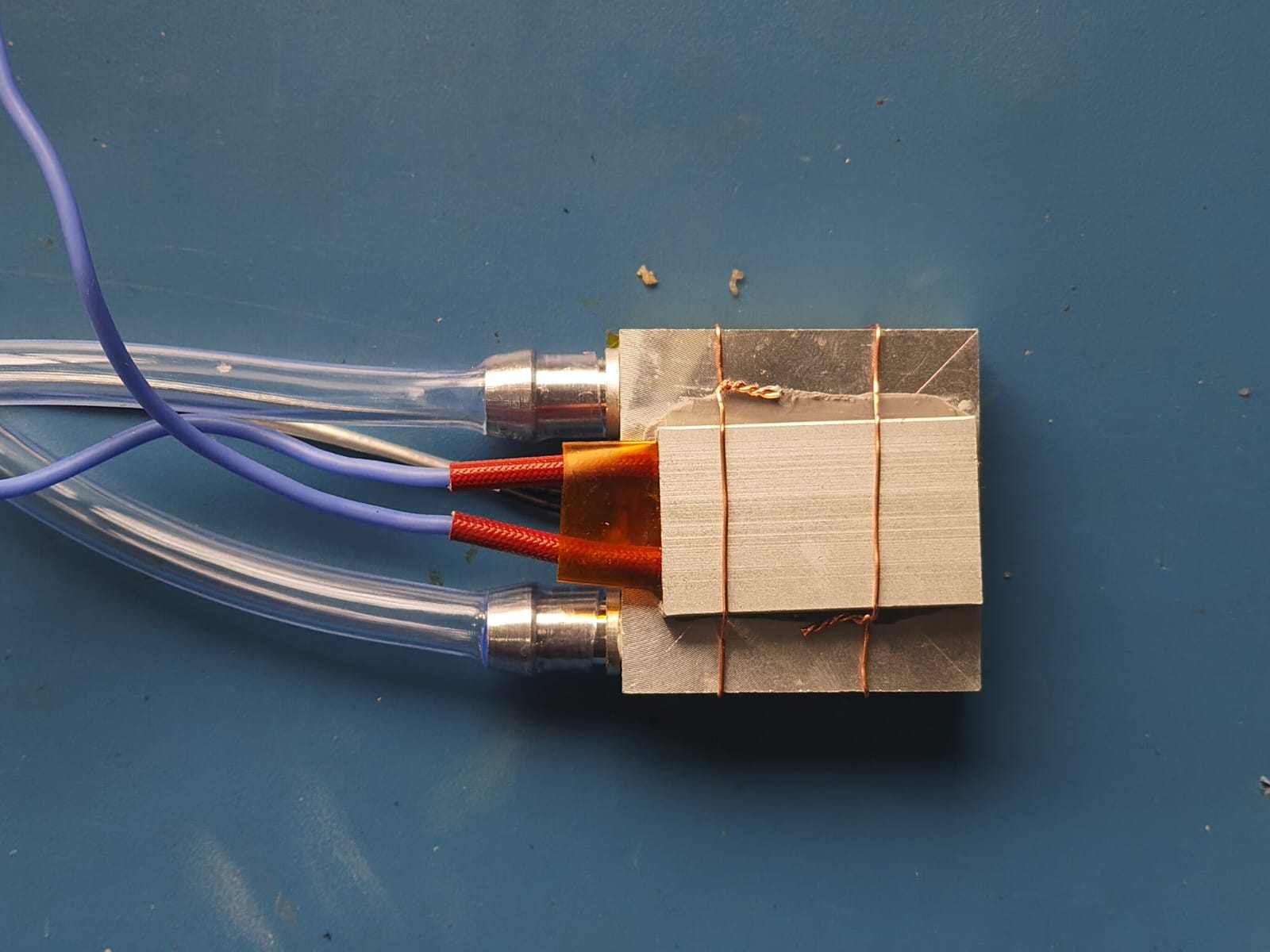
A PTC heater was then placed on top of the aluminum block. To maintain good thermal contact during casting, the heater was securely fixed using Kapton tape and copper wire. This assembly ensured that the heater and temperature sensor remained in their correct positions throughout the molding process.
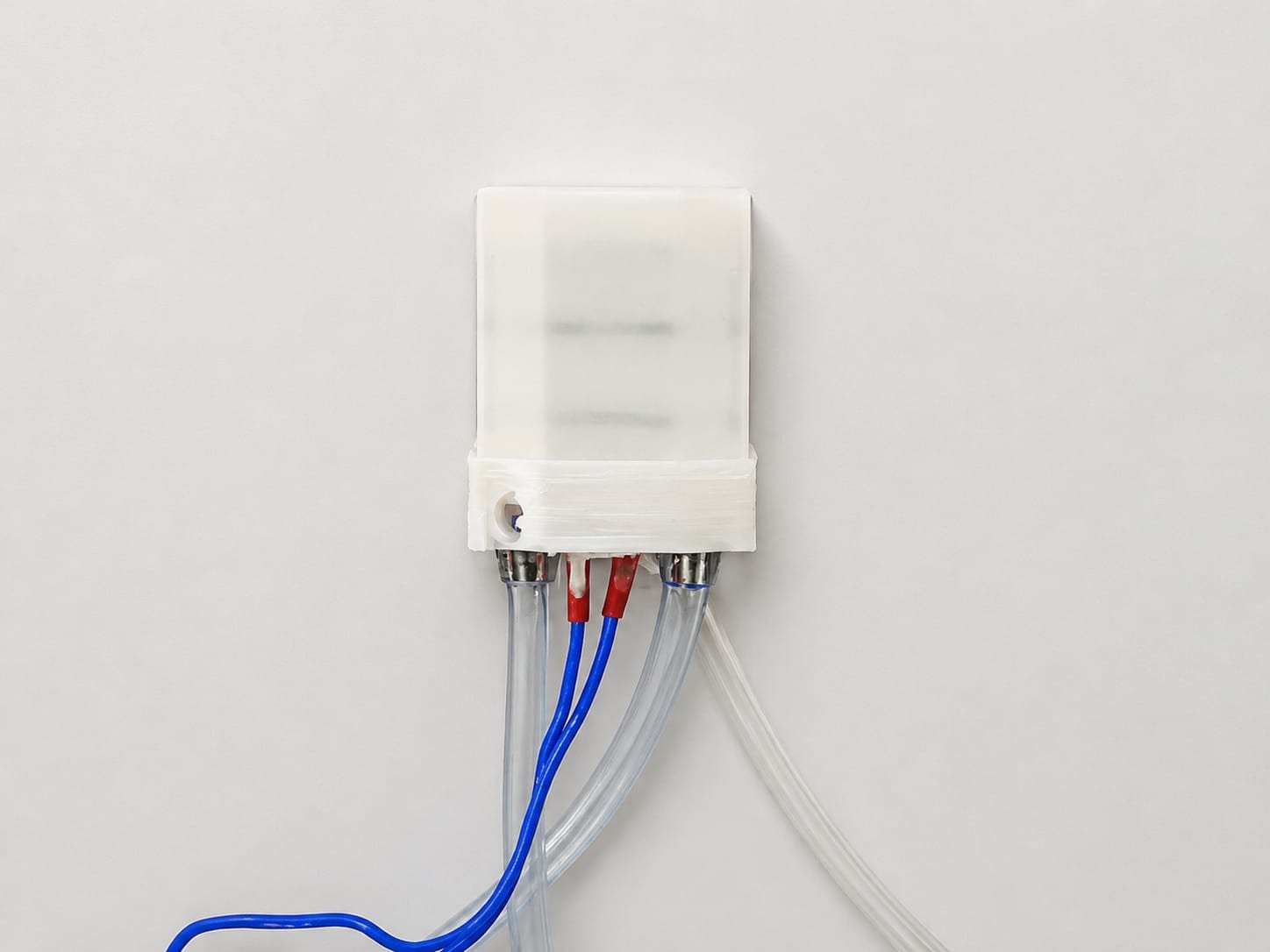
A 3D-printed enclosure was used as the mold for the silicone casting. Silicone was poured into the mold to encapsulate the aluminum block, PTC heater, and thermistor, creating a compact and insulated heating module. After the silicone had fully cured, the 3D-printed mold was carefully removed, leaving the completed silicone-cast heating assembly ready for integration into the final product.
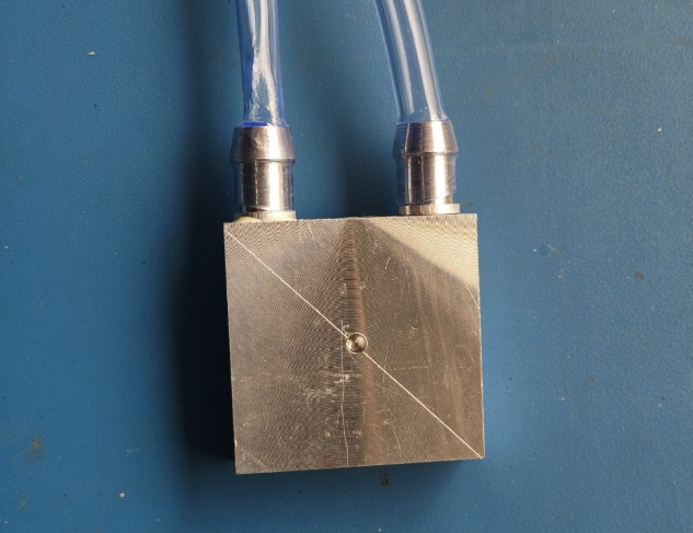
to get accurate temperature readings i put 2mm hole on the aluminum block
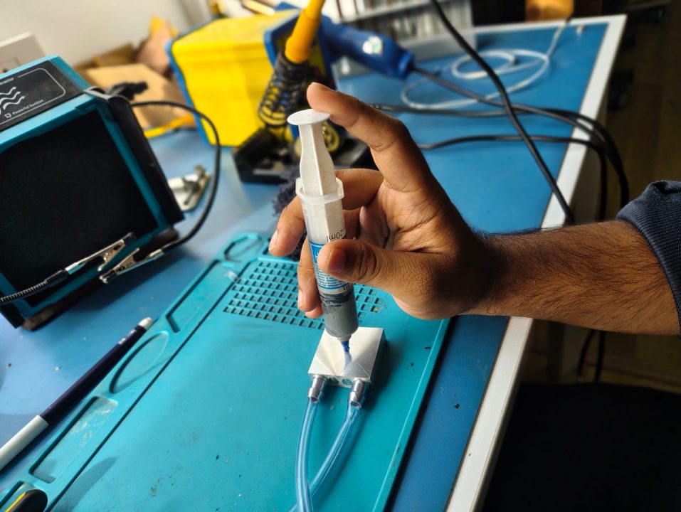
here we can see the 2mm hole drilled into the aluminum block
filling thermal paste inside the hole
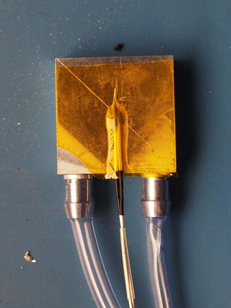
I inserted the thermistor into the hole and top of it sticked kepton tape
pasteing thermal paste on ptc heater
Now we need to combine all the components together and using copper wire we need to tite it
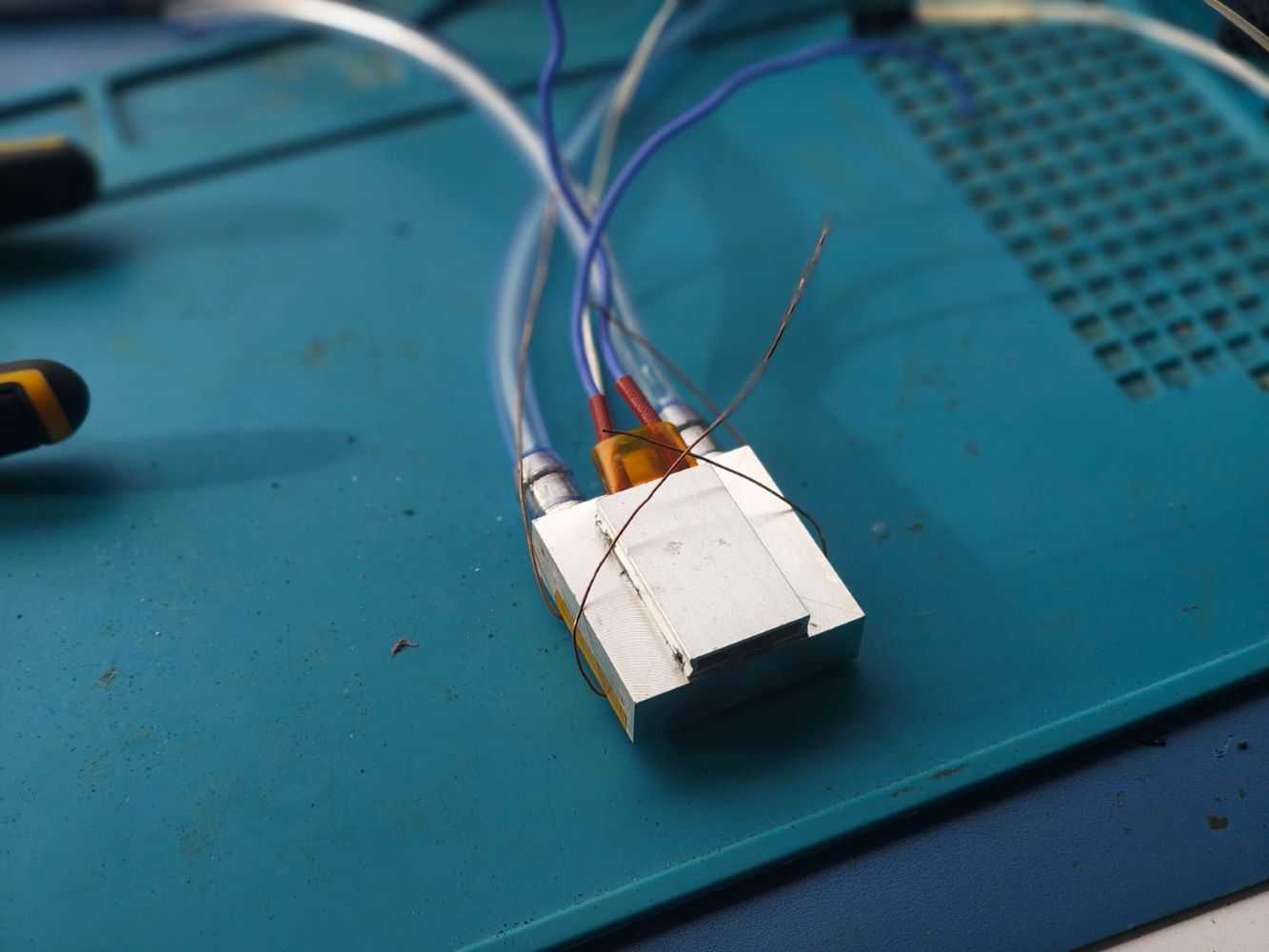
now i made a 3d printed mold for the silicone casting and put the assembly inside
These images show the assembled aluminum heating block with the PTC heater, NTC thermistor, silicone encapsulation, and fluid connections.
3D Printing the Parts
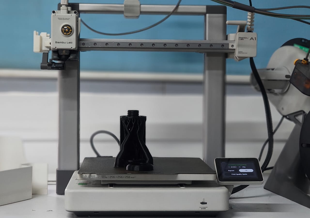
After completing the design, I 3D printed all the parts using a Bambu Lab A1 3D printer. I used eSUN PLA filament.
post processing
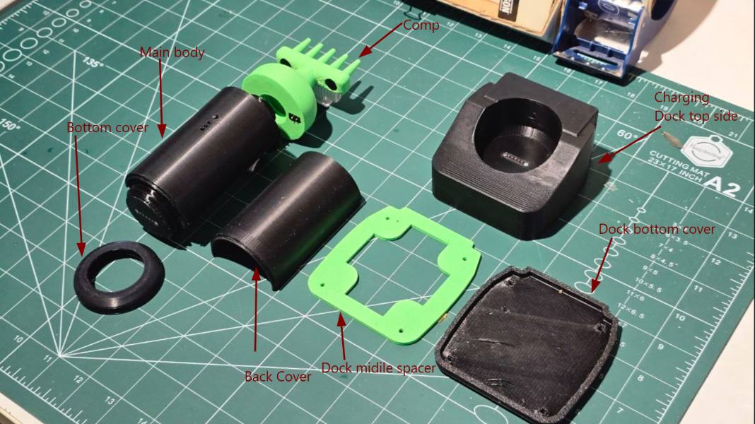
After post process
Assembling the Final Product
assembling charging dock
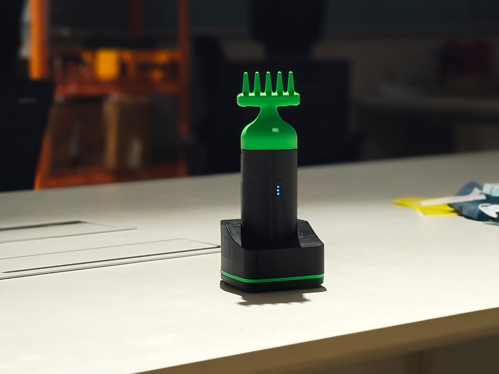
Final product
What Tasks Have Been Completed, and What Tasks Remain?
some process didint go as i planed so i decided to make new chart
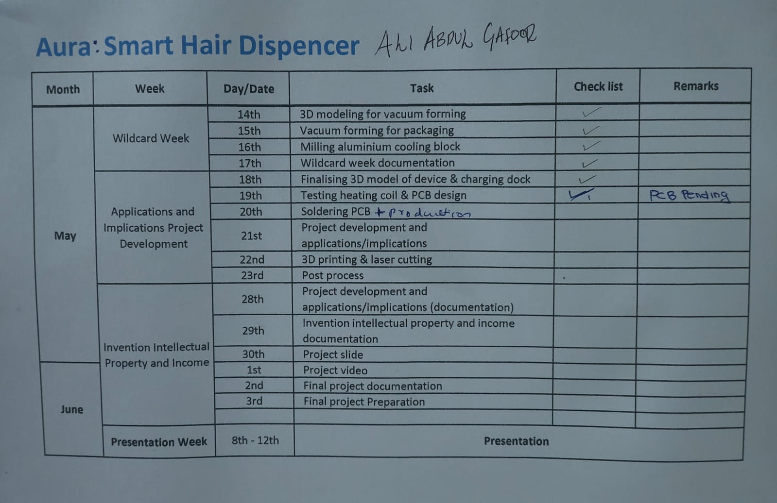
this is new chart i added all remaining tasks

What's Working? What's Not?
My final project is almost working successfully. The oil heating system, vibration motor, battery charging, PCB, and other electronic parts are working properly. There are only two small issues left. First, I forgot to add a main power switch to the PCB. Second, the oil filling hole is too small, so I need to make it a little bigger to make filling the oil easier.
What Questions Need to Be Resolved?
Most of the planned features have been completed, tested, and are working properly. There are only a few small improvements left before the final version:
- Increase the size of the oil filling hole to make filling easier.
- Add a main power ON/OFF switch.
- Reduce the overall weight of the product.
What Have I Learned?
- I learned how to plan and build a complete product from an idea to a working prototype.
- I learned to design 3D models in Fusion 360 and print them using the Bambu Lab 3D printer. I improved the design by testing many versions.
- I learned how to machine an aluminum block using the TRAK milling machine. This helped me make the heating and oil flow system for my project.
- I learned how to design a PCB in KiCad and mill it using the Carvera PCB milling machine. I also learned soldering and testing electronic components.
- I learned how to connect sensors, a heater, a vibration motor, and a battery to make all the parts work together.
- I learned that testing is very important. Some ideas did not work, so I changed the design and tried again until I got better results.
Continue Exploring
I have completed the Project Development documentation. Continue to the System Integration page to see how the electronics, mechanical design, enclosure, and software were combined into one working system. You can also visit the Final Project page to see the completed Smart Hair Oil Dispenser with its features, final assembly, and demonstration video.