Week 10 Output Devices
Objectives
- Group assignment: Measure the power consumption of an output device
- Individual assignment: Add an output device to a microcontroller board you've designed, and program it to do something.
Group Assignment
As part of the group assignment, we calculated the power consumption of a Servo motor and NeoPixel LEDs using a bench power supply. Group Assignment
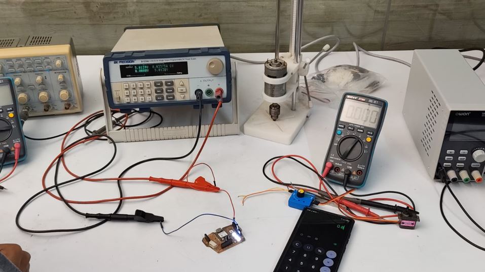
To calculate the power consumed by a device, we measured the supply voltage and current using a DC power supply or multimeter and then applied the following formula:
Power (W) = Voltage (V) × Current (A)
For the NeoPixel test setup:
- Supply Voltage: 5 V
- Measured Current: 0.0337 A
Thus, Power = 5 × 0.0337 = 0.1685 W. Therefore, the three NeoPixels consumed approximately 0.17 W of power during the test.
To know more, visit Group Assignment.
Output Devices
An output device is a hardware component that receives data or commands from a microcontroller, processor, or computer and converts them into a form that humans can perceive or use. These devices translate electronically processed information into visual, auditory, or mechanical outputs to interact with the real world. This week I wanted to explore OLED display.
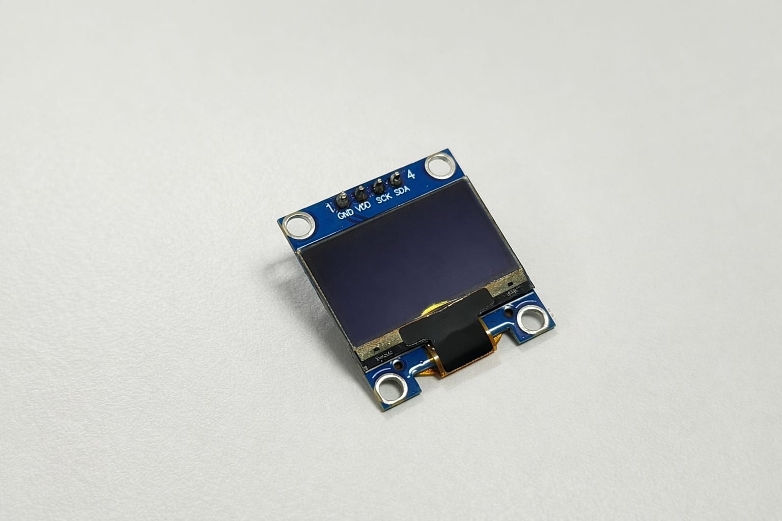
OLED Display (Organic Light Emitting Diode)
An OLED display is a small screen that produces its own light to show text and graphics. It is low power, easy to use with microcontrollers, and commonly connected using I2C (SDA, SCL).
OLED Layer Structure
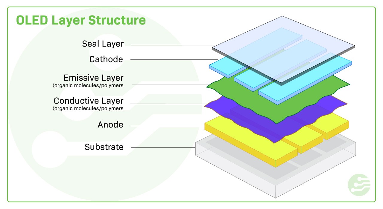
- Current is applied between the cathode and anode.
- As electricity flows from the cathode to the anode, the cathode gains electrons while the anode loses electrons.
- This creates electron holes in the conductive layer.
- Electrons meet electron holes at the boundary between emissive and conductive layers.
- Electrons recombine with holes and release energy in the form of light (photons).
How do OLEDs work?
An OLED is a type of LED in which the emitting layer is made of organic compounds that produce light when an electric current is applied. The layer typically consists of a polymer substance sandwiched between two electrodes, a cathode, and an anode. When a current is applied, it causes the organic molecules to emit light.
OLEDs work similarly to LEDs, but instead of using n-type and p-type semiconductor layers, they use organic compound layers to produce light.
What makes OLED special?
- Each pixel (tiny dot) produces its own light
- No need for backlight (unlike LCD)
- Works well in dark and bright environments
- Uses low power
Why we use OLED in projects
- Easy to connect with microcontrollers like ATtiny, Arduino, or RP2040
- Small size (commonly 0.96 inch)
- Displays useful information like:
- Temperature
- Sensor values
- Messages or icons
Common type used
- SSD1306 OLED display
- Communication: I2C (SDA, SCL pins)
Basic connections
- VCC — Power (3.3V or 5V)
- GND — Ground
- SDA — Data line
- SCL — Clock line
Advantages of OLED
- Slim and light
- High contrast
- Wide operating temperatures
- Vibrant colors
- Wide viewing angles
- Deep black colors
- Fast response times
- Energy efficient
Coin Vibration Motor (ERM)
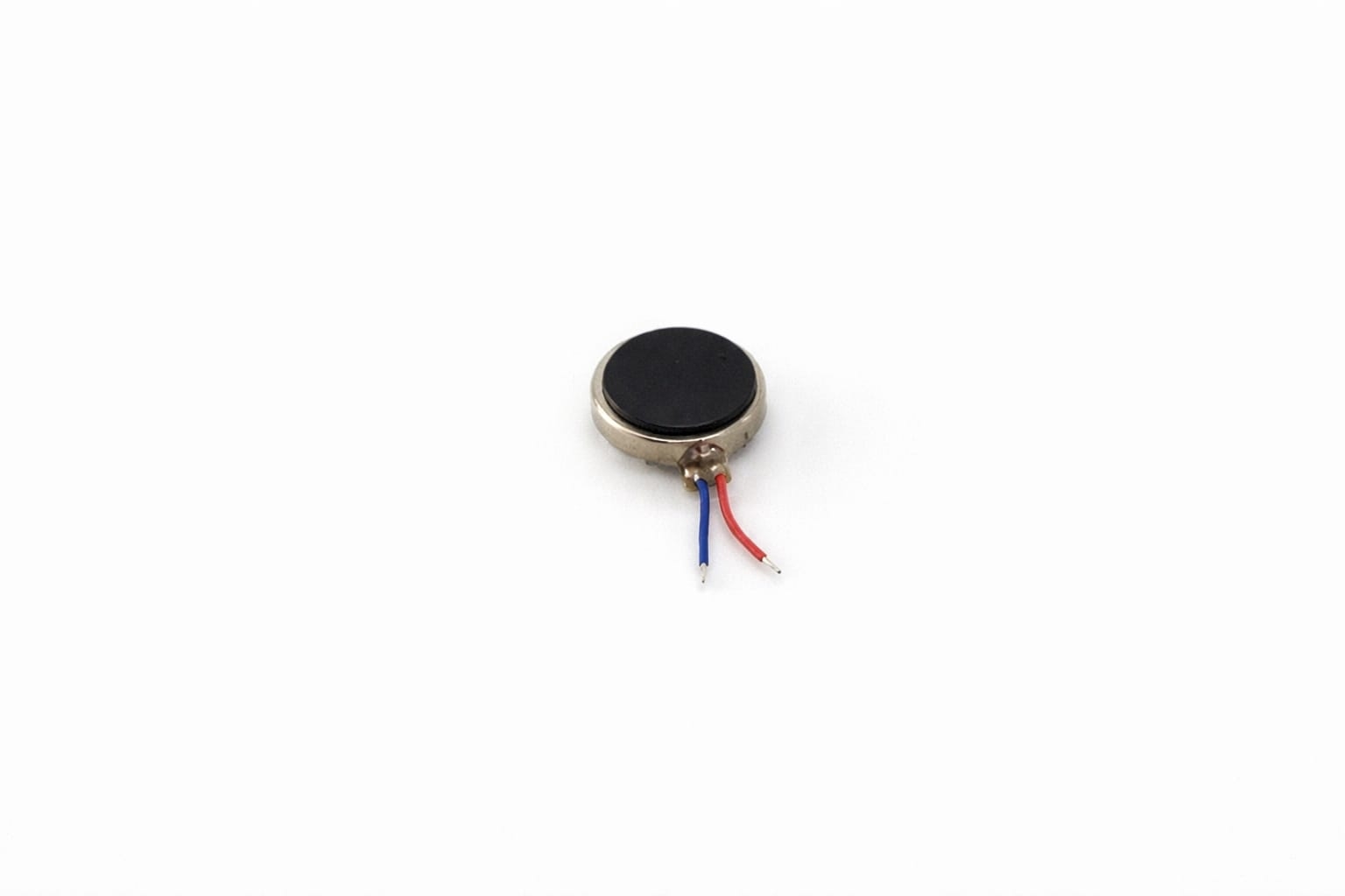
Coin Type Vibration Motor (ERM)
A coin-type vibration motor is a compact actuator used to generate vibration in electronic devices. It works on the principle of an eccentric rotating mass (ERM), where a small unbalanced weight attached to a DC motor shaft rotates to produce vibration. Due to its flat and lightweight design, it is commonly used in wearable devices, mobile phones, and alert systems. In this project, the motor is used as an output device to provide haptic feedback and notification signals.
Vibrator Inside
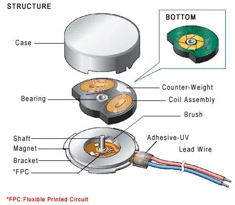
Working Principle
- Inside the motor, a DC motor rotates an eccentric mass
- This creates unbalanced centrifugal force
- Result — Vibration is produced
Vibration strength depends on:
- Supply voltage
- Motor speed
Mechanical Specifications
| Parameter | Typical Value |
|---|---|
| Shape | Flat Coin Type |
| Diameter | 8 mm – 12 mm |
| Thickness | 2.5 mm – 4 mm |
| Weight | ~3 grams |
| Mounting | Adhesive backing (double tape) |
Electrical Specifications
| Parameter | Typical Value |
|---|---|
| Rated Voltage | 3V (2V–5V range) |
| Current Consumption | 60–100 mA |
| Starting Voltage | ~2V |
| Speed | ~10,000 RPM |
| Control | PWM supported |
Seeed Studio XIAO RP2040
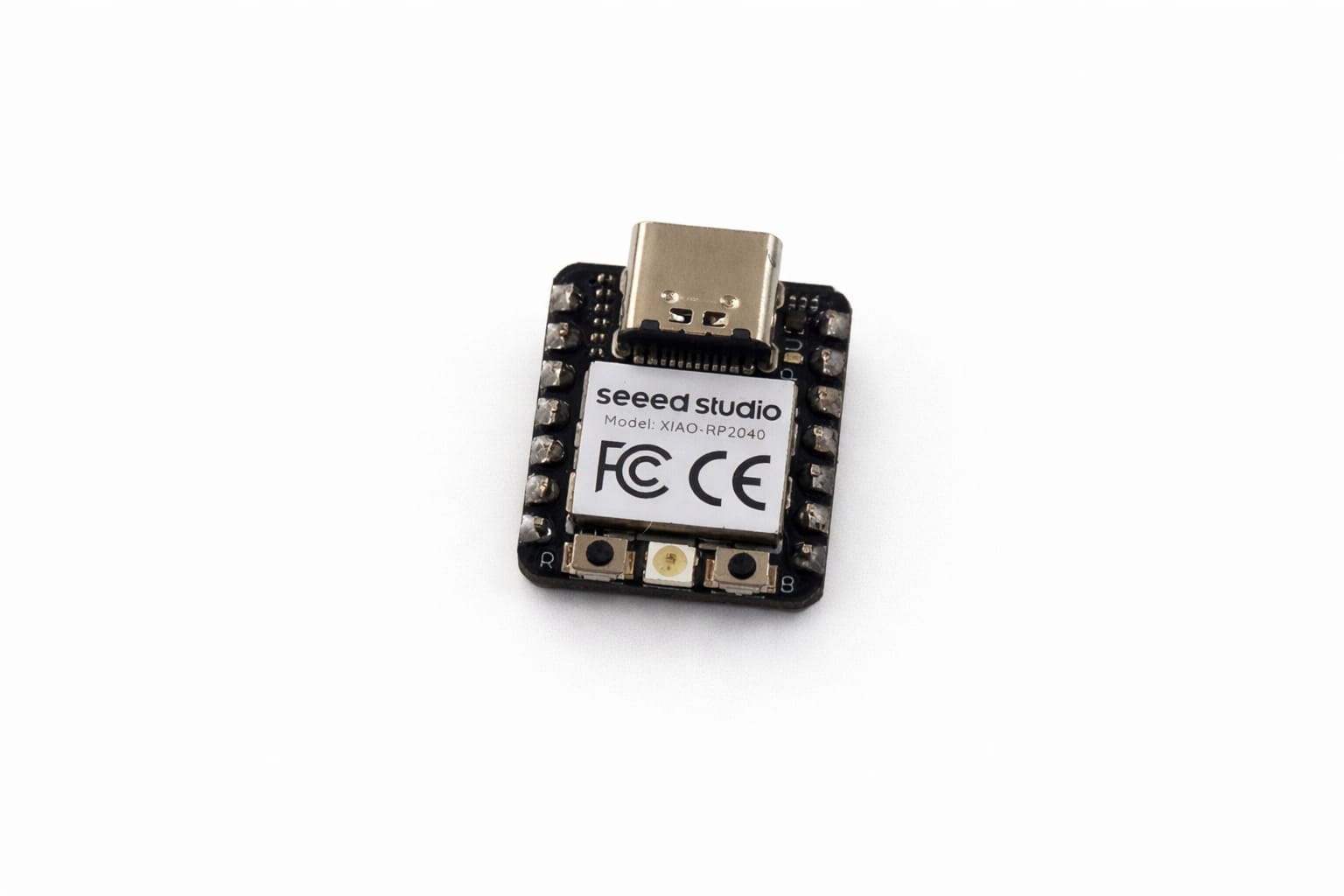
Overview
The Seeed Studio XIAO RP2040 is a compact and powerful microcontroller board based on the RP2040 chip developed by Raspberry Pi. It features a dual-core ARM Cortex-M0+ processor and is designed for embedded systems, IoT devices, and wearable electronics. Due to its small size and high performance, it is widely used in modern electronics projects.
Working Principle
- The RP2040 executes programmed instructions using Arduino IDE, MicroPython, or C/C++
- It receives input from sensors, switches, or communication modules
- Processes data using its dual-core processor
- Controls output devices like OLED displays, motors, LEDs, etc.
Mechanical Specifications
| Parameter | Typical Value |
|---|---|
| Board Size | 21 mm × 17.5 mm |
| Weight | ~2 grams |
| Connector | USB Type-C |
| Mounting | Castellated Pins / SMD Pads |
Electrical Specifications
| Parameter | Typical Value |
|---|---|
| Microcontroller | RP2040 (Dual-core ARM Cortex-M0+) |
| Operating Voltage | 3.3V |
| Input Voltage | 5V via USB Type-C |
| Clock Speed | Up to 133 MHz |
| Flash Memory | 2 MB |
| SRAM | 264 KB |
| GPIO Pins | 11 multifunction GPIO |
| ADC | 12-bit (up to 4 channels) |
| PWM Channels | Up to 16 |
| Communication | I2C, SPI, UART |
| USB | USB 1.1 (Device & Host) |
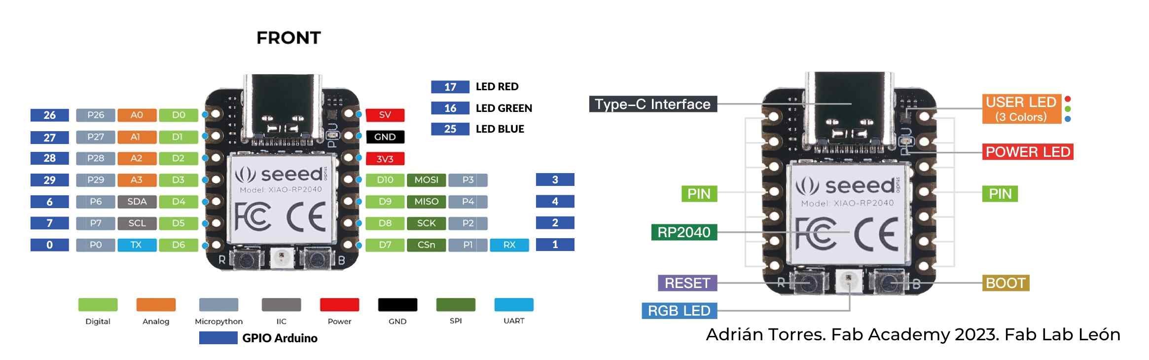
Pin Configuration
- GPIO pins support digital input/output
- Supports I2C (SDA, SCL)
- Supports SPI communication
- Supports UART communication
- ADC pins for analog input
- PWM pins for motor and LED control
Fabrication Notes
- Use only 3.3V logic for GPIO pins
- Do not apply 5V directly to GPIO
- Ensure proper USB access for programming
- Use pull-up resistors (4.7k–10k) for I2C lines
- Provide stable power supply
Applications
- Embedded systems
- Wearable devices
- IoT applications
- Sensor interfacing
- Automation systems
- Display-based projects (OLED)
Pinout Diagram
NeoPixel LED (WS2812B)
Overview
NeoPixel LEDs (WS2812B) are individually addressable RGB LEDs with an integrated driver chip. Each LED can display a wide range of colors and brightness levels using a single data line. They are widely used in interactive projects, decorative lighting, and embedded systems.
Working Principle
- Each LED contains an internal controller (WS2812B IC)
- Microcontroller sends serial digital data through one wire
- Each LED captures its data and passes remaining data to next LED
- Allows multiple LEDs to be connected in series (daisy-chain)
Mechanical Specifications
| Parameter | Typical Value |
|---|---|
| Package Type | SMD 5050 |
| Size | 5 mm × 5 mm |
| Mounting | SMD / LED Strip / Module |
Electrical Specifications
| Parameter | Typical Value |
|---|---|
| Operating Voltage | 5V |
| Current (per LED) | ~60 mA (max brightness white) |
| Logic Voltage | 3.3V – 5V compatible |
| Communication | Single-wire digital protocol |
| Control Signal | PWM (internal) |
| Data Rate | ~800 kHz |
| Color Type | RGB (Red, Green, Blue) |
| Color Depth | 24-bit (16 million colors) |
Pin Configuration
- VCC — 5V power supply
- GND — Ground
- DIN — Data input from microcontroller
- DOUT — Data output to next LED
Fabrication Notes
- Use external 5V supply for multiple LEDs
- Add 330Ω resistor in series with data line
- Add 1000µF capacitor across VCC and GND
- Ensure common ground with microcontroller
- Avoid long data wires without proper shielding
Applications
- Decorative lighting
- Wearable electronics
- Status indicators
- Interactive installations
- LED animations and displays
I2C Connector (SMD JST Port)
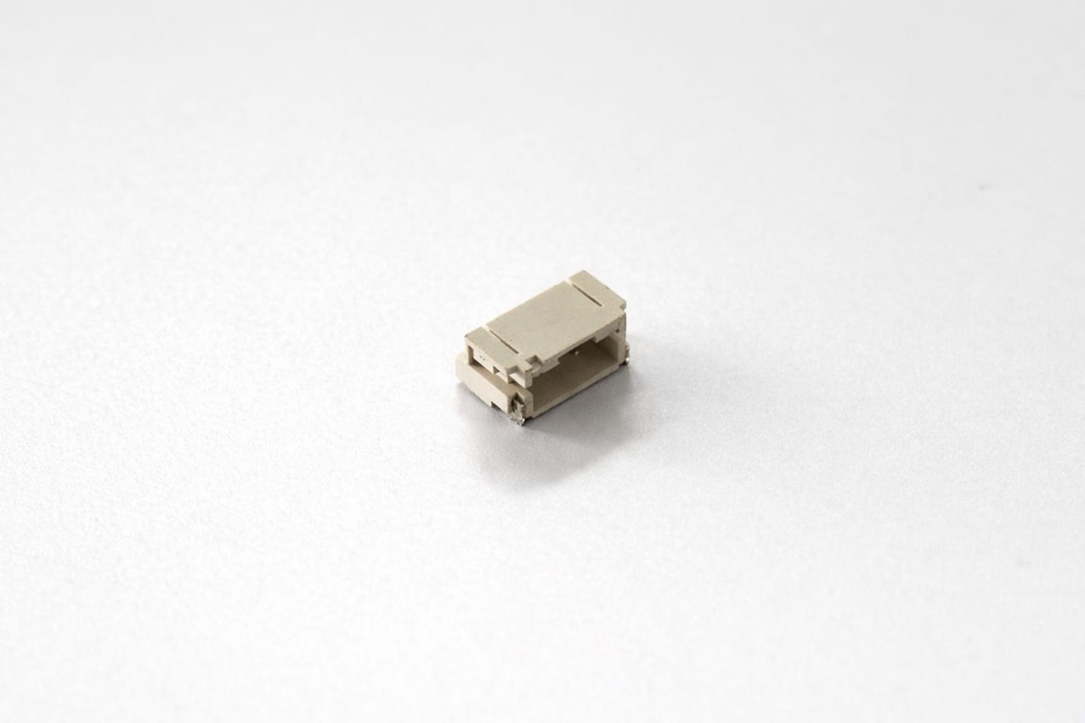
Overview
The I2C connector is a compact Surface Mount Device (SMD) interface used to connect external modules such as OLED displays and sensors. It simplifies wiring by providing a standardized 4-pin interface for power and communication using the I2C protocol. This connector is widely used in embedded systems and modular electronics projects.
Working Principle
- I2C (Inter-Integrated Circuit) uses two communication lines: SDA and SCL
- SDA (Serial Data) transfers data between devices
- SCL (Serial Clock) synchronizes communication
- Devices are addressed uniquely, allowing multiple modules on the same bus
- Pull-up resistors are required for proper communication
Mechanical Specifications
| Parameter | Typical Value |
|---|---|
| Connector Type | JST / SMD Connector |
| Mounting Type | Surface Mount Device (SMD) |
| Pin Count | 4 Pins |
| Pitch | 1.0 mm – 2.0 mm |
| Orientation | Right Angle / Top Entry |
| Material | Plastic Housing with Metal Contacts |
| Color | White / Beige |
| Dimensions | Approx. 5 mm × 4 mm × 3 mm |
Electrical Specifications
| Parameter | Typical Value |
|---|---|
| Operating Voltage | 3.3V / 5V |
| Current Rating | Up to 1A (typical) |
| Communication Protocol | I2C (Two-wire) |
| Signal Lines | SDA, SCL |
Pin Configuration
| Pin | Function |
|---|---|
| 1 | VCC (3.3V / 5V) |
| 2 | GND |
| 3 | SDA (Serial Data) |
| 4 | SCL (Serial Clock) |
Fabrication Notes
- Ensure correct orientation of the connector before soldering
- Use pull-up resistors (4.7k–10k) for SDA and SCL lines
- Keep I2C traces short to reduce noise
- Avoid sharp bends in PCB routing
- Verify pin order before connecting external modules
Applications
- OLED display connection
- Temperature and humidity sensors
- IoT modules
- Embedded communication interfaces
- Modular electronics systems
Tactile Push Button Switch
Note on Input Control
Although this week focuses on output devices, a tactile push button was used in the design to control and switch between different output modes such as vibration patterns, LED effects, and display states. The button acts as a simple user interface to interact with the system.
- Used for switching between output modes
- Helps in testing different behaviors of output devices
- Not considered as a primary input study for this week
Working of MOSFET
A MOSFET (Metal-Oxide-Semiconductor Field-Effect Transistor) controls current flow between its source and drain terminals by varying the voltage applied to its gate. It consists of a semiconductor body with an insulating oxide layer separating the gate from the channel. When a voltage is applied to the gate, an electric field modifies the conductivity of the channel, allowing or restricting current flow. MOSFETs operate in two modes: enhancement mode, where no current flows without a gate voltage, and depletion mode, where a conductive channel exists by default and can be turned off with a gate voltage. There are two main types: N-channel MOSFETs, where electrons are the primary charge carriers and current flows when the gate is positively biased, and P-channel MOSFETs, where holes are the charge carriers and current flows when the gate is negatively biased. N-channel MOSFETs are generally preferred for high-speed and high-efficiency applications due to their lower resistance and faster switching characteristics. Here I am using an N-channel MOSFET.
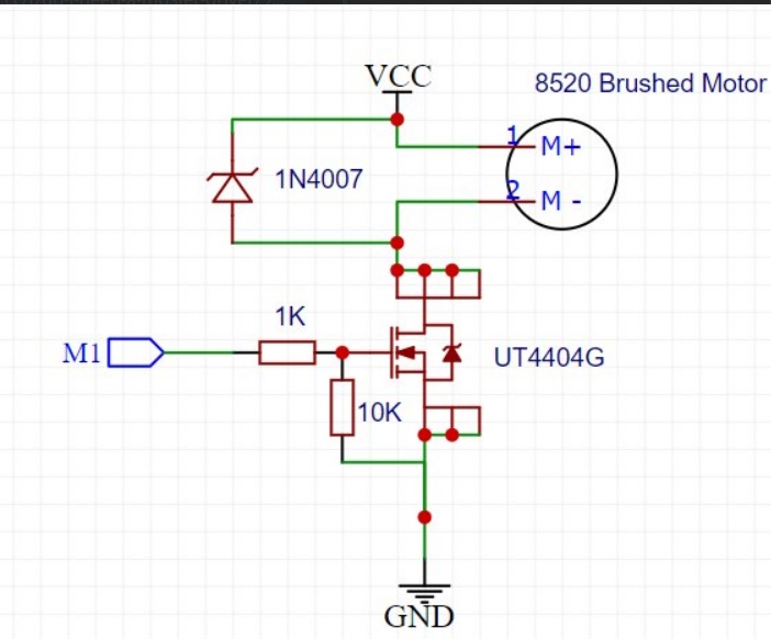
Simple Explanation
| Part | Function |
|---|---|
| Gate (G) | Control pin that receives signal from microcontroller |
| Drain (D) | Connected to load (motor/light) |
| Source (S) | Connected to ground |
| Rin (Gate Resistor) | Limits current from input signal and protects MOSFET |
| Rgs (Pull-down Resistor) | Keeps MOSFET OFF when no input signal is present |
| Working (ON State) | When input voltage is HIGH, MOSFET turns ON and current flows from drain to source, powering the load |
| Working (OFF State) | When input is LOW, MOSFET turns OFF and stops current flow |
Designing PCB in KiCad
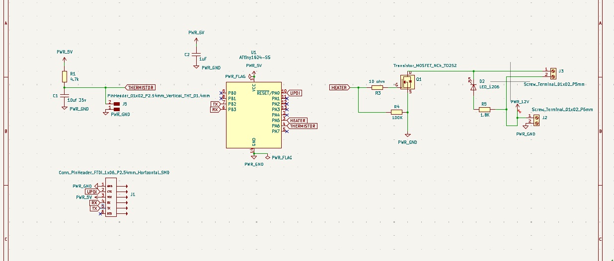
The circuit uses a XIAO RP2040 as the main controller, along with a MOSFET to drive a vibration motor, a Schottky diode for protection, a NeoPixel (WS2812B) LED for visual output, resistors for signal stability, a push button for input, and an I2C connector to connect devices like an OLED display.
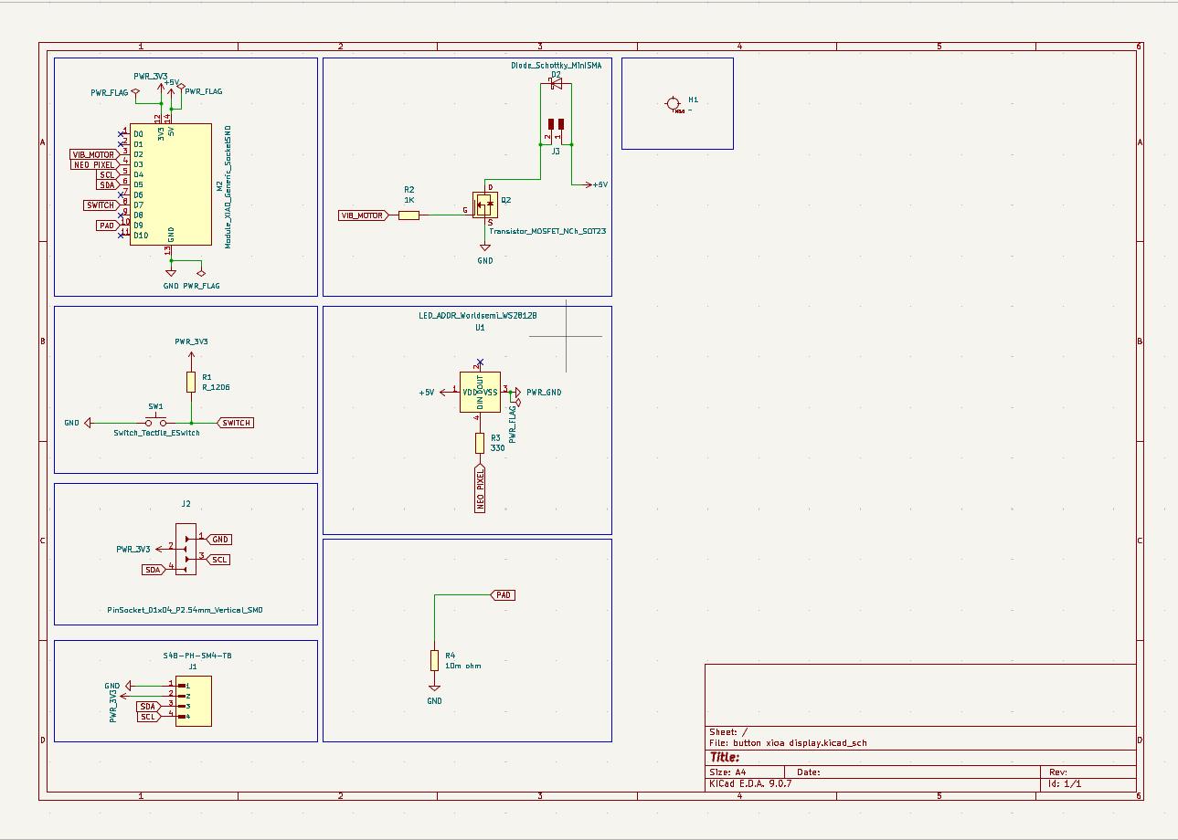
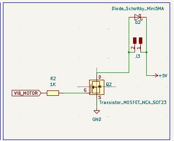
This circuit uses an N-channel MOSFET to control a vibration motor from a microcontroller signal. A Schottky diode is added across the motor to protect the circuit from reverse voltage spikes.
This is a NeoPixel (WS2812B) RGB LED connected to 5V and GND, controlled by a single data pin from the microcontroller. It can display different colors based on the signal received.
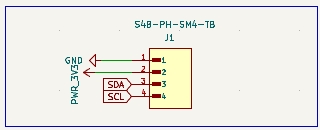
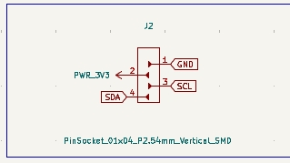
This is an I2C connector with 4 pins: VCC (3.3V), GND, SDA, and SCL. It is used to connect devices like an OLED display or sensors to the microcontroller.
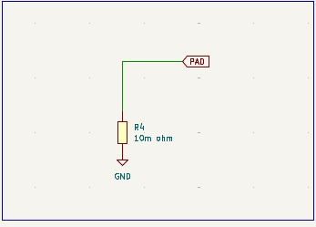
This is a touch pad input connected to the microcontroller, where touching the pad changes the signal. The resistor to ground helps stabilize the signal and detect touch properly.
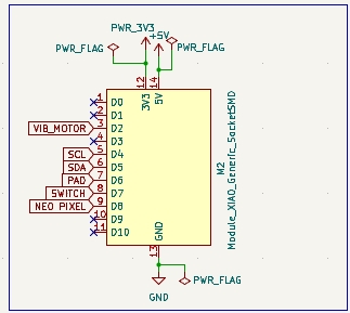
This is an SMD XIAO RP2040 microcontroller module, which acts as the main control unit of the circuit. It reads inputs (button/touch) and controls outputs like the motor and NeoPixel LED using its GPIO pins.
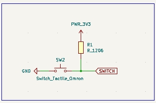
This is a push button switch with a pull-up resistor, where the resistor keeps the signal HIGH and pressing the button connects it to GND (LOW). It is used as a simple input for the microcontroller.
This is a 4-pin SMD header (I2C interface) providing 3.3V, GND, SDA, and SCL connections. It is used to easily connect external modules like sensors or an OLED display.
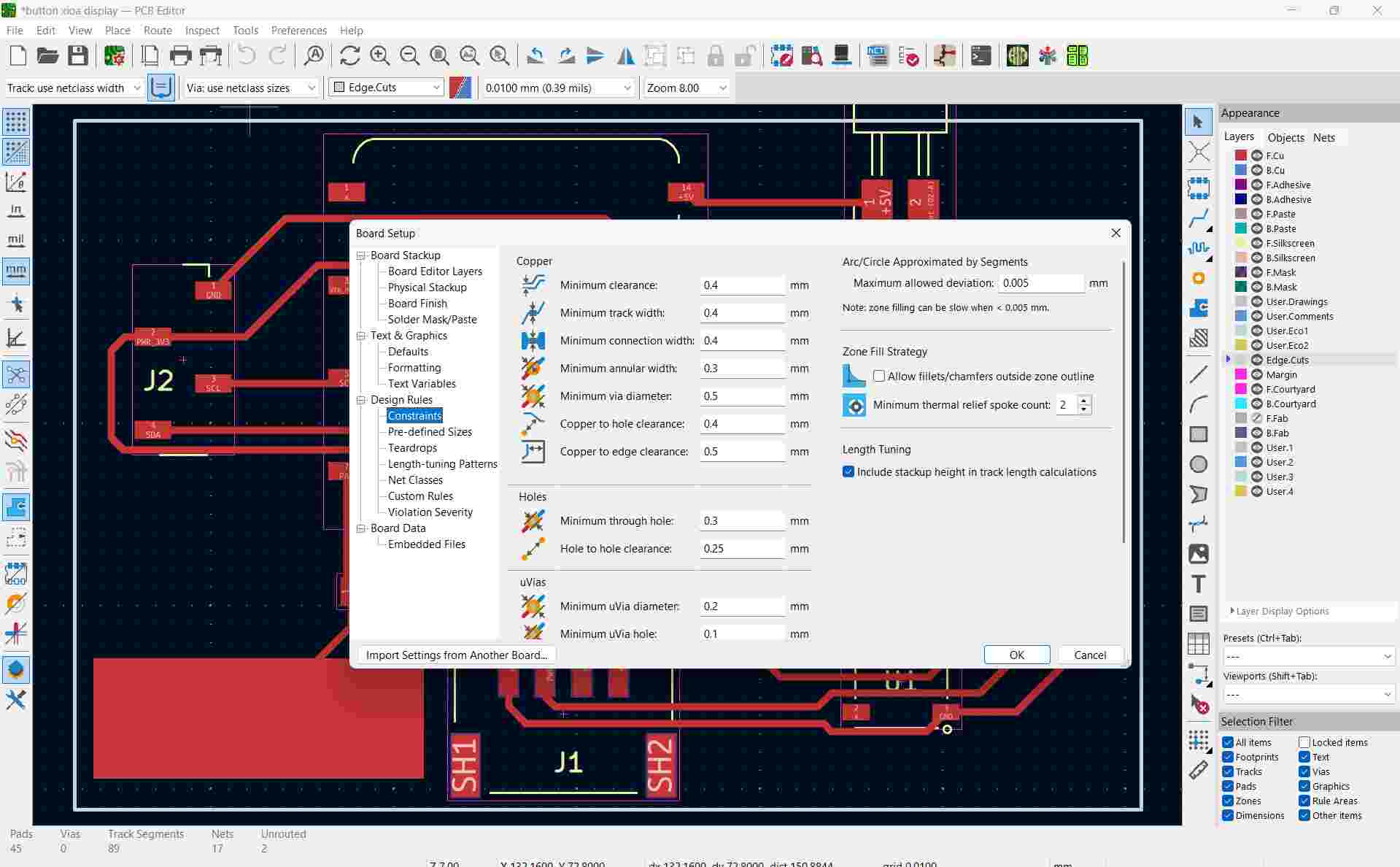
These constraints settings in KiCad define the minimum values for track width, spacing, via size, and clearances to ensure the PCB is manufacturable and avoids short circuits or design errors.
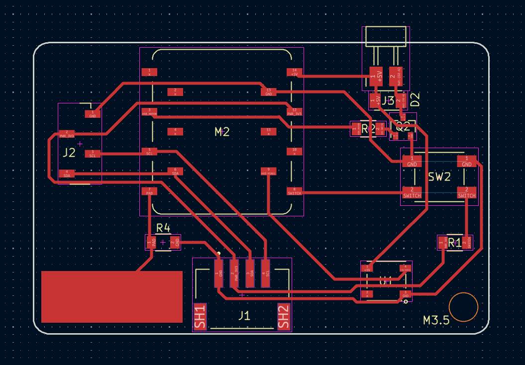
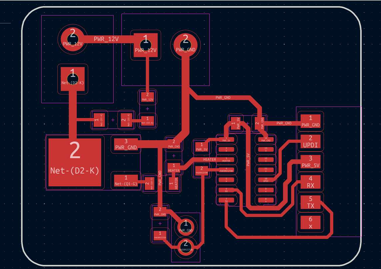
These PCB tracks are copper paths that connect all components like the XIAO RP2040, MOSFET, NeoPixel, and connectors, allowing signals and power to flow through the circuit. The routing is done carefully to avoid overlap, maintain spacing, and ensure reliable connections.
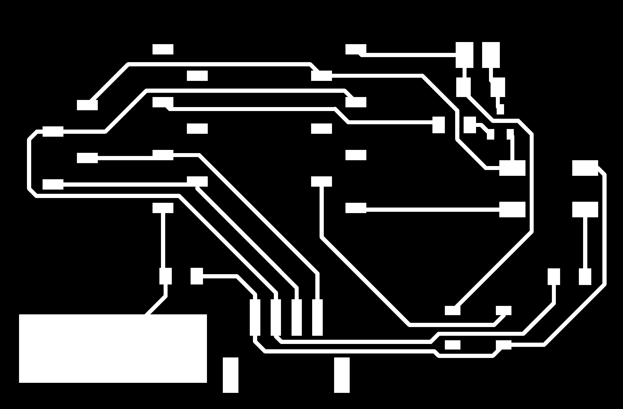
Use rules checker to verify the connections. Now we have to change the file to gerber format. Then I uploaded the gerber files in Gerber to png software to convert it to PNG format. For double layer PCB we have five layers to mill.
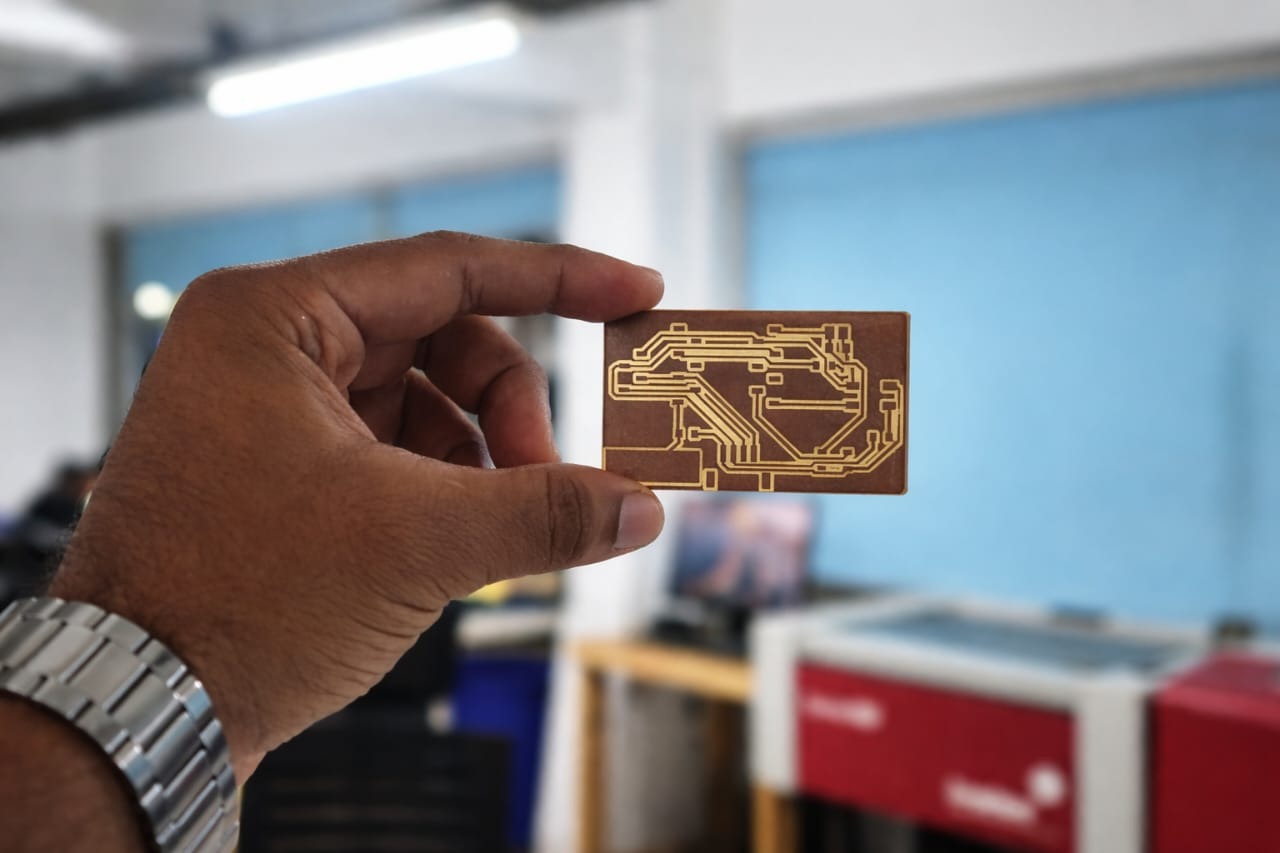
PCB Output

Milling the PCB
The Roland Modela MDX-20 machine is used for PCB milling. We need to manually set the zero position (X, Y, and Z axes). Load the 1/64" engraving bit and set the X and Y axes at a corner of the board. Then, lower the bit slowly until it just touches the PCB surface and set Z = 0. After that, upload the top trace layer, calculate the toolpath, and send the file to the machine for milling.
After milling the first layer, carefully replace the bit with a 1/32" drill bit for vias, holes and outline cuts. Re-zero only the Z-axis, keeping X and Y unchanged. Resume milling.
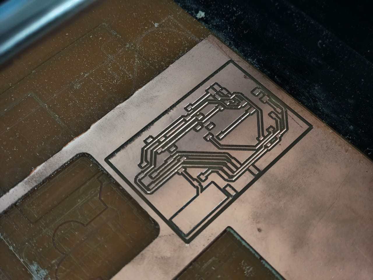
Load the engraving bit and zero the Z-axis again. Run the bottom layer trace milling. Then change the bit. Cut the PCB outline using a 1/32" end mill. Here is the final result.
Assembling the components
I requested the components from fabstash and collected them from the inventory. I used the interactive HTML BOM in KiCad to get the list of components. It also highlights where to place components on the PCB.
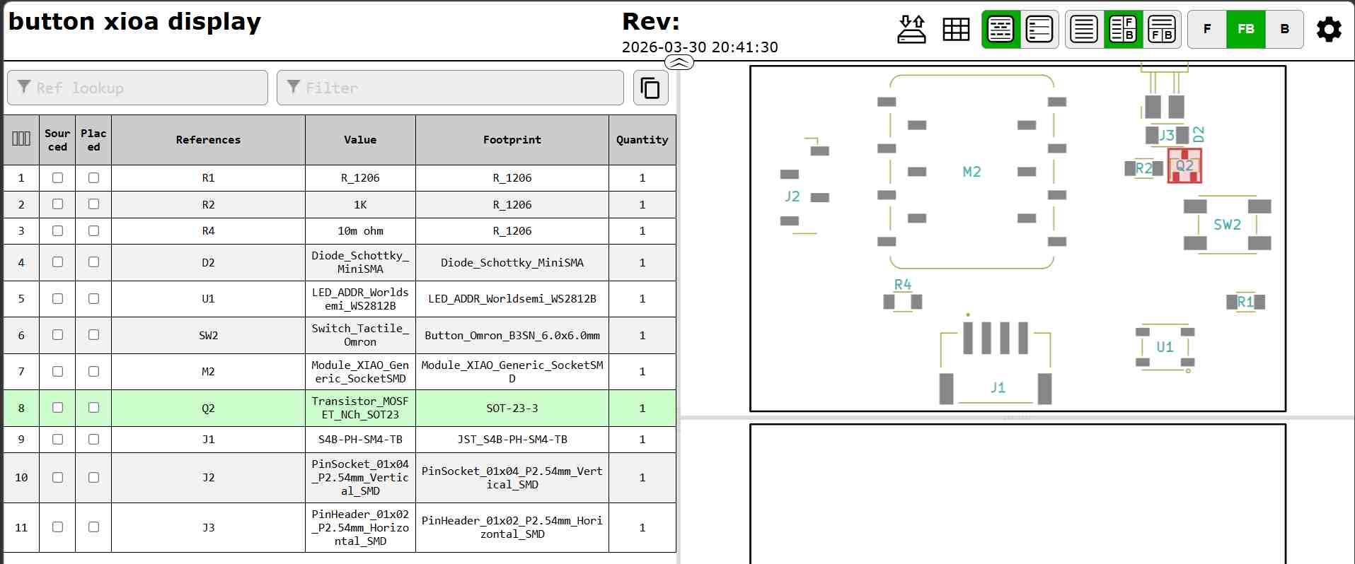
The following components were used to design and fabricate the PCB for the vibration feedback system:
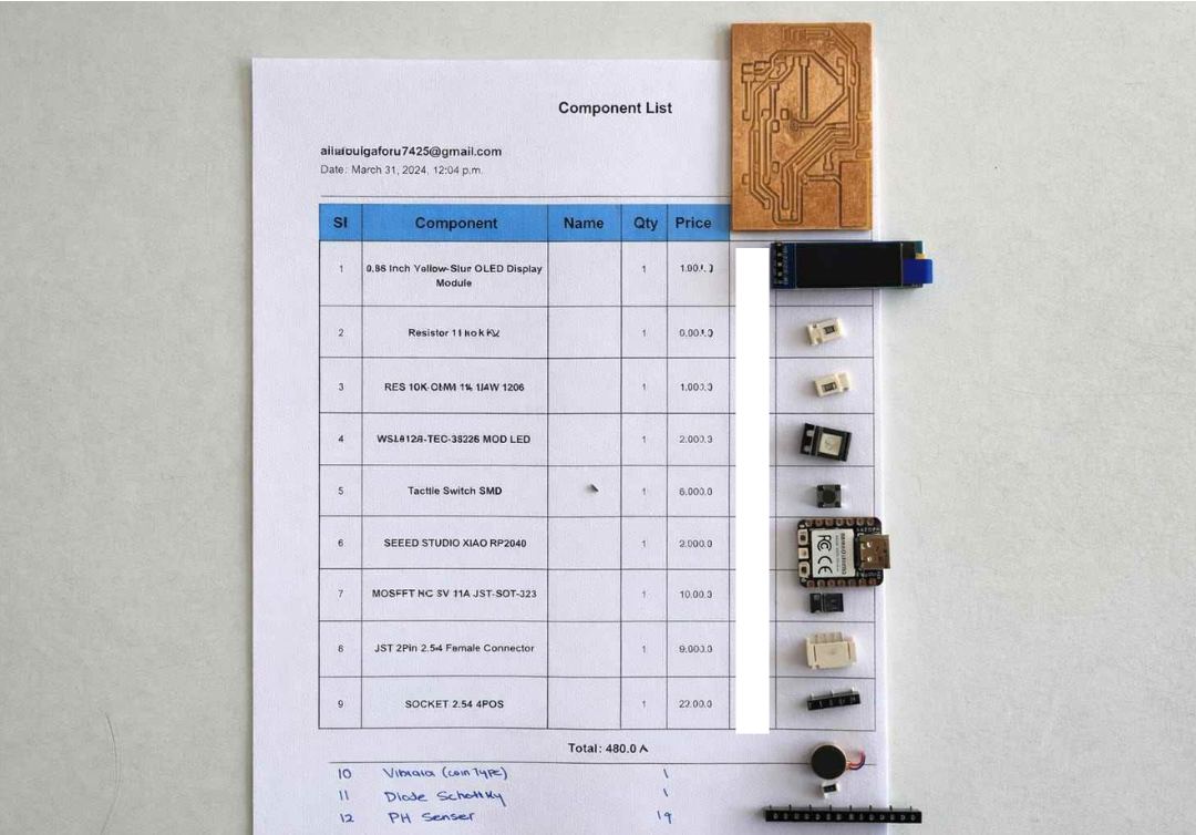
Note: The image was partially masked because some component labels were incorrectly written during selection. The masking was done to avoid confusion.
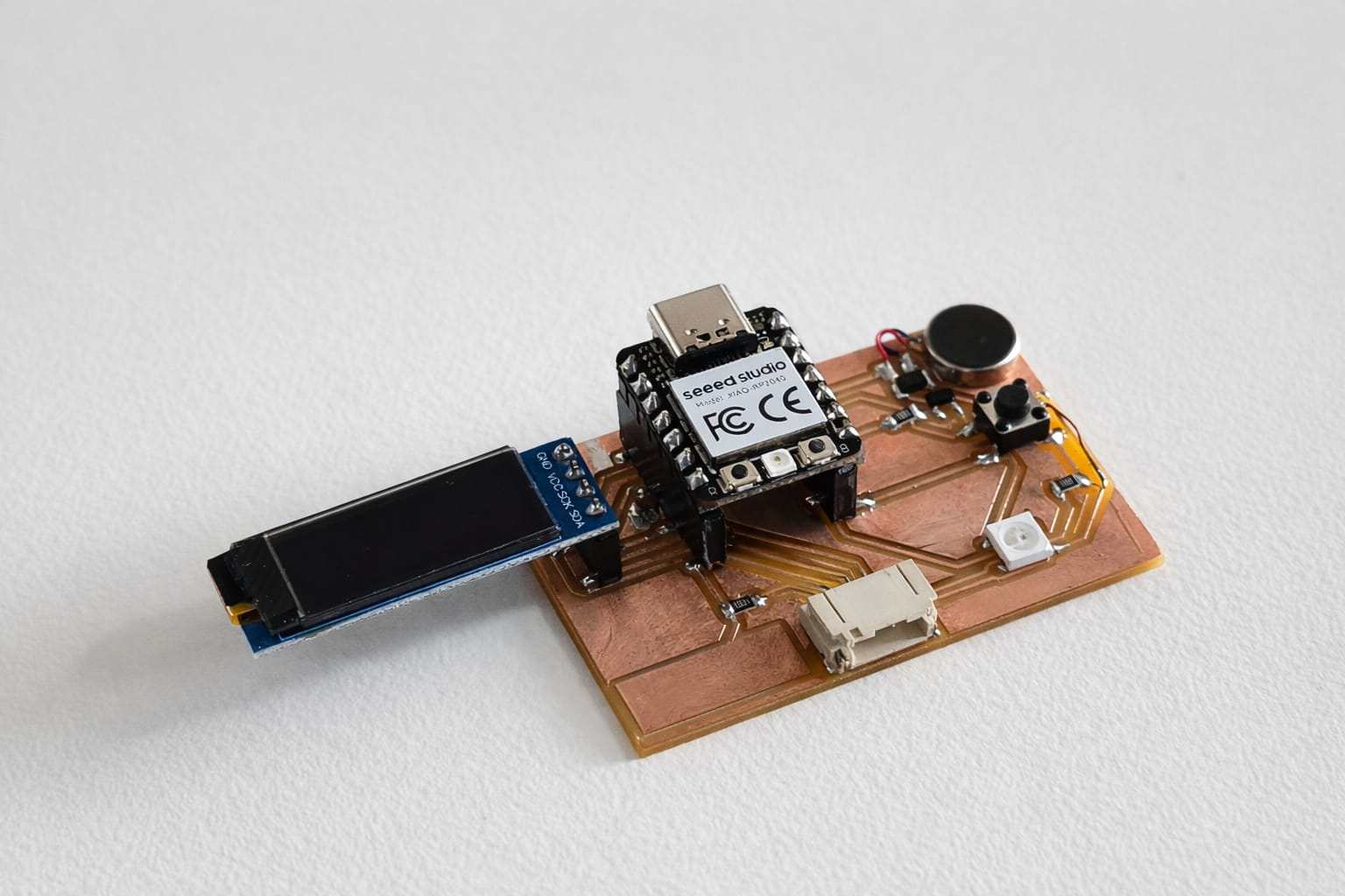
The PCB was assembled by soldering all components.
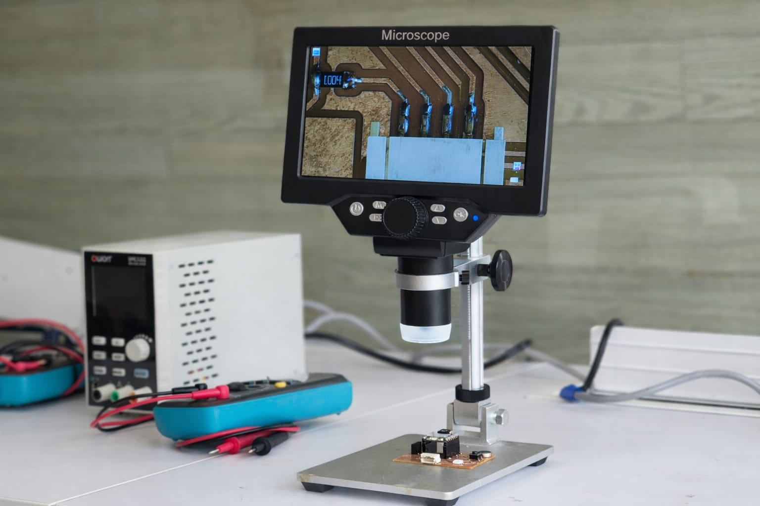
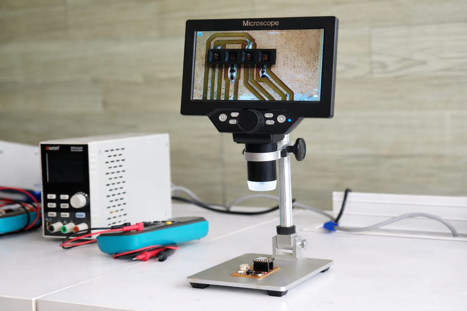
Inspecting the PCB
The first step is microscope inspection, which focuses on visually examining the PCB for physical defects. Check for issues such as poor solder joints, solder bridges, cracked components, or broken traces. Ensure that all components are correctly placed and aligned.
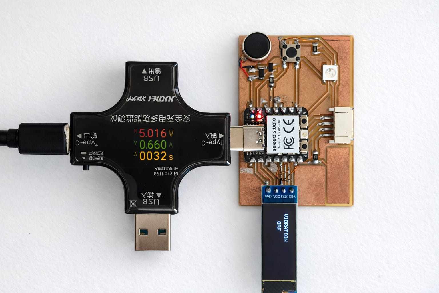
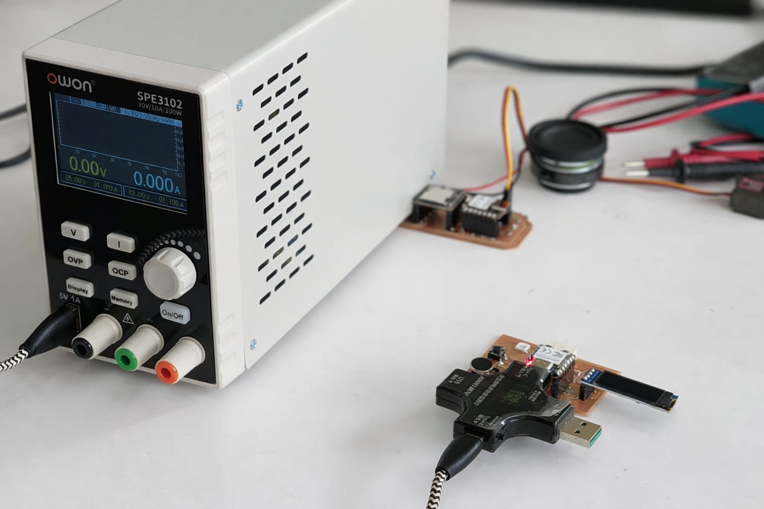
Testing
The PCB was tested for short circuits and voltage drops using a USB tester and power supply. The circuit worked properly with stable voltage and no short circuit issues.
Programming the PCB
Code Reference
This code was developed with the assistance of ChatGPT.
I Already mentioned about how to install oled liberery in Embedded Programming
#include <Wire.h>
#include <Adafruit_GFX.h>
#include <Adafruit_SSD1306.h>

#define SCREEN_WIDTH 128
#define SCREEN_HEIGHT 32

#define SDA_PIN D4
#define SCL_PIN D5
#define BUTTON_PIN D7
#define MOTOR_PIN D2

Adafruit_SSD1306 display(SCREEN_WIDTH, SCREEN_HEIGHT, &Wire, -1);

int mode = 1;
bool lastButtonState = HIGH;

unsigned long pressStart = 0;
int intensity = 80;

void setup() {
  pinMode(BUTTON_PIN, INPUT_PULLUP);
  pinMode(MOTOR_PIN, OUTPUT);

  Wire.setSDA(SDA_PIN);
  Wire.setSCL(SCL_PIN);
  Wire.begin();

  display.begin(SSD1306_SWITCHCAPVCC, 0x3C);
  display.setRotation(1);  // portrait

  display.clearDisplay();
  updateDisplay();
}

void loop() {
  bool buttonState = digitalRead(BUTTON_PIN);

  if (lastButtonState == HIGH && buttonState == LOW) {
    pressStart = millis();
  }

  if (lastButtonState == LOW && buttonState == HIGH) {
    unsigned long pressTime = millis() - pressStart;

    if (pressTime > 800) {
      if (mode != 4) {
        intensity += 30;
        if (intensity > 255) intensity = 80;
      }
    } else {
      mode++;
      if (mode > 4) mode = 1;

      if (mode == 1) intensity = 80;
      if (mode == 2) intensity = 150;
      if (mode == 3) intensity = 255;
      if (mode == 4) intensity = 0;
    }

    updateDisplay();
    delay(200);
  }

  lastButtonState = buttonState;

  analogWrite(MOTOR_PIN, intensity);
}

void updateDisplay() {
  display.clearDisplay();
  display.setTextColor(WHITE);

  int16_t x1, y1;
  uint16_t w, h;

  // MODE (small)
  display.setTextSize(1);
  String title = "MODE";
  display.getTextBounds(title, 0, 0, &x1, &y1, &w, &h);
  int xTitle = (32 - w) / 2;

  // NUMBER (big)
  display.setTextSize(2);
  String text = (mode == 4) ? "0" : String(mode);
  display.getTextBounds(text, 0, 0, &x1, &y1, &w, &h);
  int xNum = (32 - w) / 2;

  // vertical center
  int startY = 40;

  // Draw
  display.setTextSize(1);
  display.setCursor(xTitle, startY);
  display.println(title);

  display.setTextSize(2);
  display.setCursor(xNum, startY + 12);
  display.println(text);

  display.display();
}
AI Image Prompt
chat gpt prompt: I lost original prompt of this code. I told "Genarate code. HERE IAM USING XIAO RP2040 in D2 I CONNECTECTED COIN VIBRATION MOTOR, IN D4 I CONNECTED SCL, IN D5 SDA, IN D6 PAD, D7 PUSH BUTTON, PIN 13 GND, PIN14 VCC. GENARATE A C++ CODE. I NEED 3 MODE OF VIBRATION SLOW, MEDIUM, FAST. AND IN OLED DISPLAY MODE NEED TO SHOW AND CHANGE ACCORDING TO VIBRATION"
AI Tool Used: ChatGPT
Hero Shot
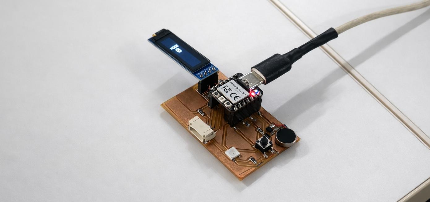
Problem
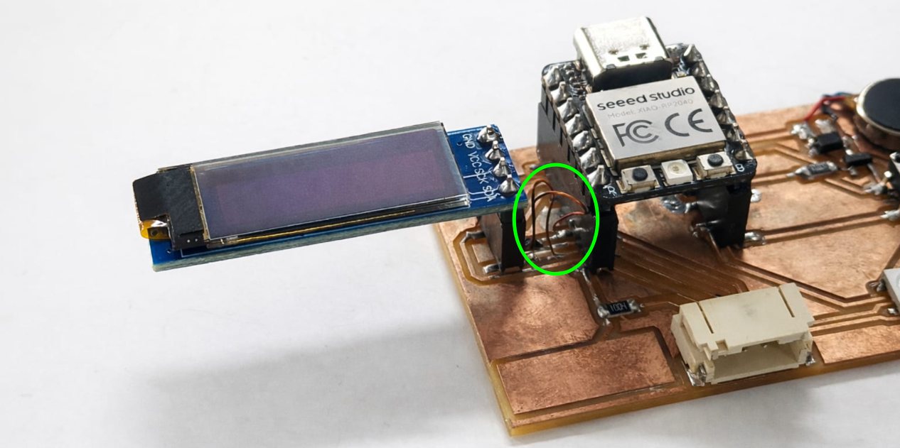
when iwas trying to blink neopixel led its not working there is 2 reson for that 1 is neopixel is not propperly solderd and other one is there is a tiny cut on pcb saheen fout that conetion is not passing through it then resolderd it using enamal wire then uploaded code again then its workes
Installing neopixel library
Code for neo pixel
#include#define LED_PIN D8 Adafruit_NeoPixel strip(1, LED_PIN, NEO_GRB + NEO_KHZ800); void setup() { strip.begin(); strip.setBrightness(30); } void loop() { strip.fill(strip.Color(255, 0, 0)); strip.show(); delay(1000); strip.fill(strip.Color(0, 255, 0)); strip.show(); delay(1000); strip.fill(strip.Color(0, 0, 255)); strip.show(); delay(1000); strip.clear(); strip.show(); delay(1000); }
AI Image Prompt
Prompt:I want a code blinking a neopixel led.using xioa rp2040.pin out for neopixel is d8. genarate a code for it
AI Tool Used: ChatGPT
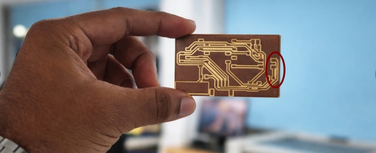
Mistakes
-
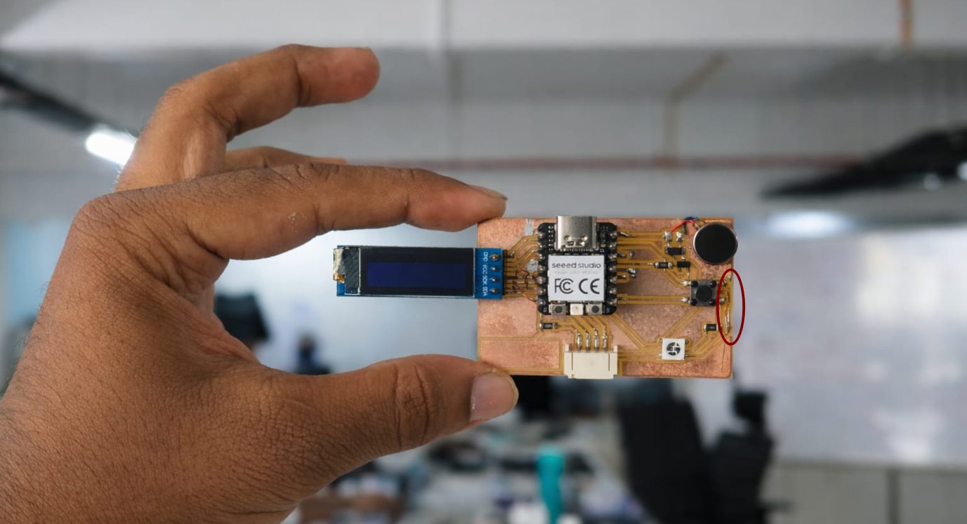
Damaged PCB Trace After Milling
One trace was damaged during the milling process. It was repaired by re-soldering using enamel-coated copper wire, which restored proper connectivity.
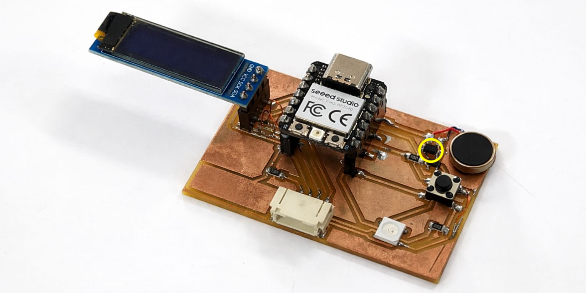
-
Diode Polarity Reversed
The diode was soldered with incorrect polarity. This issue was identified and corrected later with guidance from Shaheen.
-
OLED SDA and SCL Connections Interchanged
The OLED communication pins SDA (D4) and SCL (D5) were mistakenly interchanged during wiring. This caused communication failure and was later corrected by properly reconnecting the pins.
On Final Project Time, With Help of Saheen, I Tried a New PCB
This time, I integrated both input and output devices together, and Shaheen suggested using a thermistor instead of the DS18B20.
This is my new schematic I tried at the time of the final project, redesigned with help from Saheen.
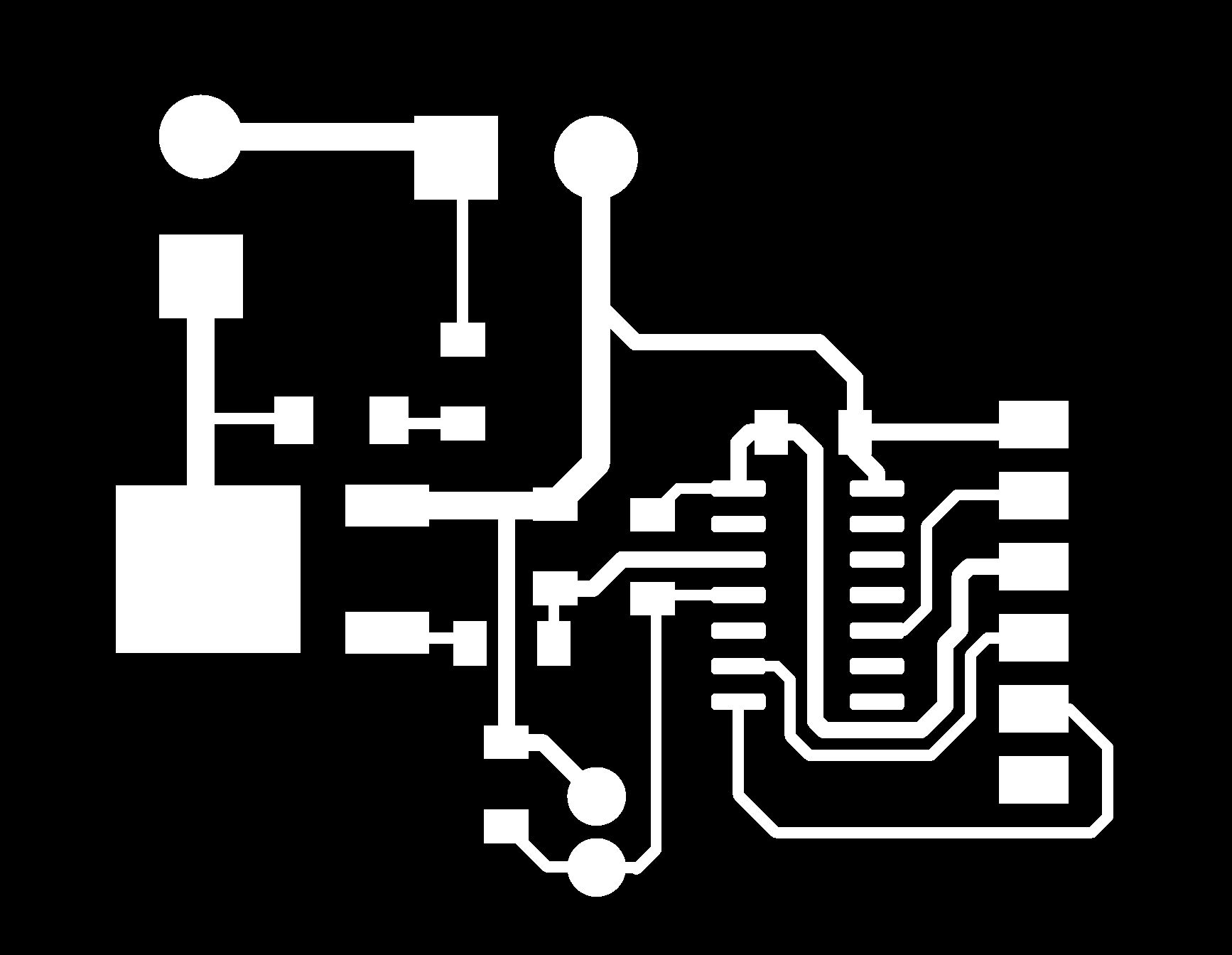
This is what my new PCB layout looks like.
I checked the traces using the rules checker tool. From File → Fabrication Outputs → Gerbers, I got the gerber format. The gerber files were uploaded to the gerber2PNG software to convert them to PNG format.
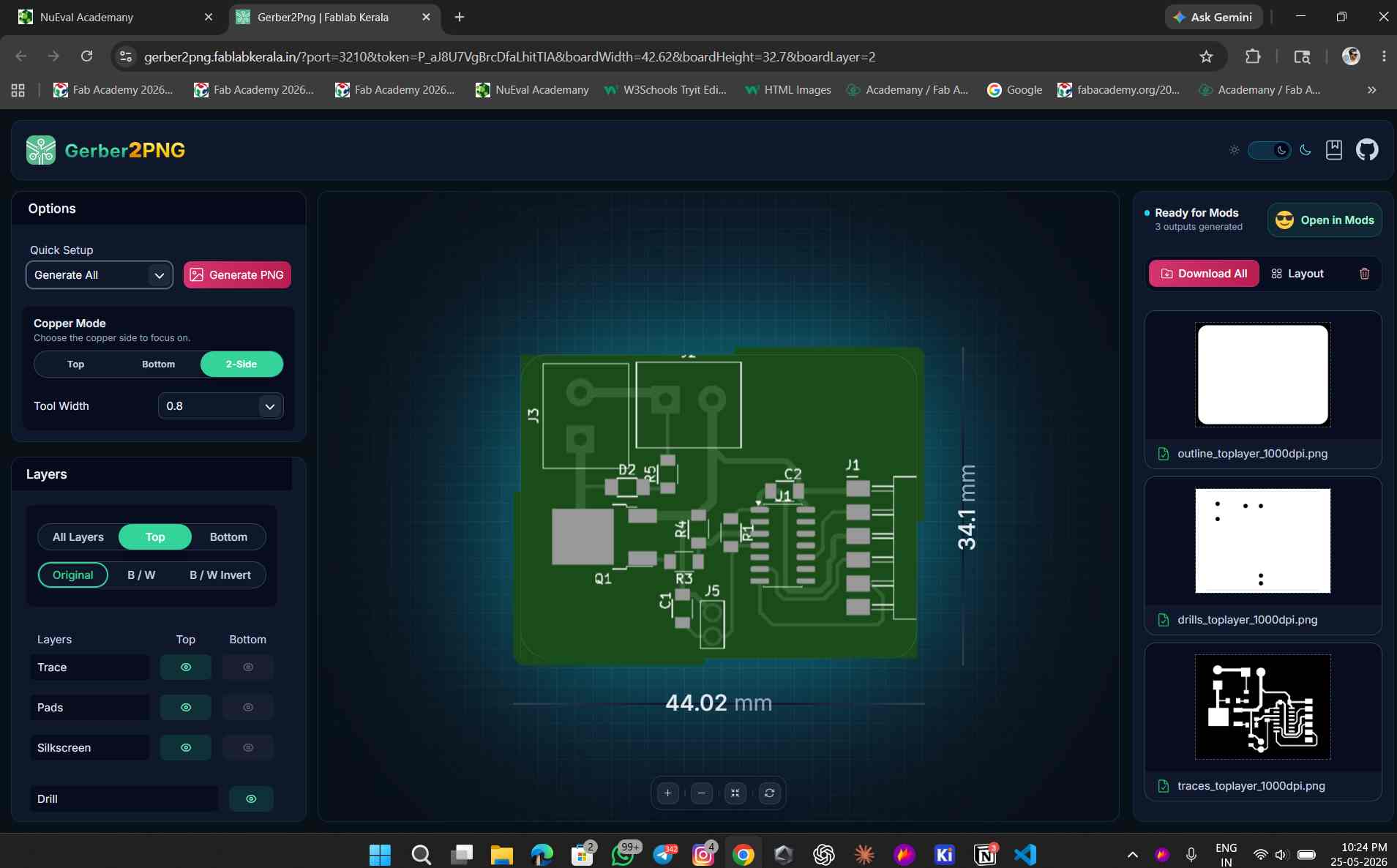
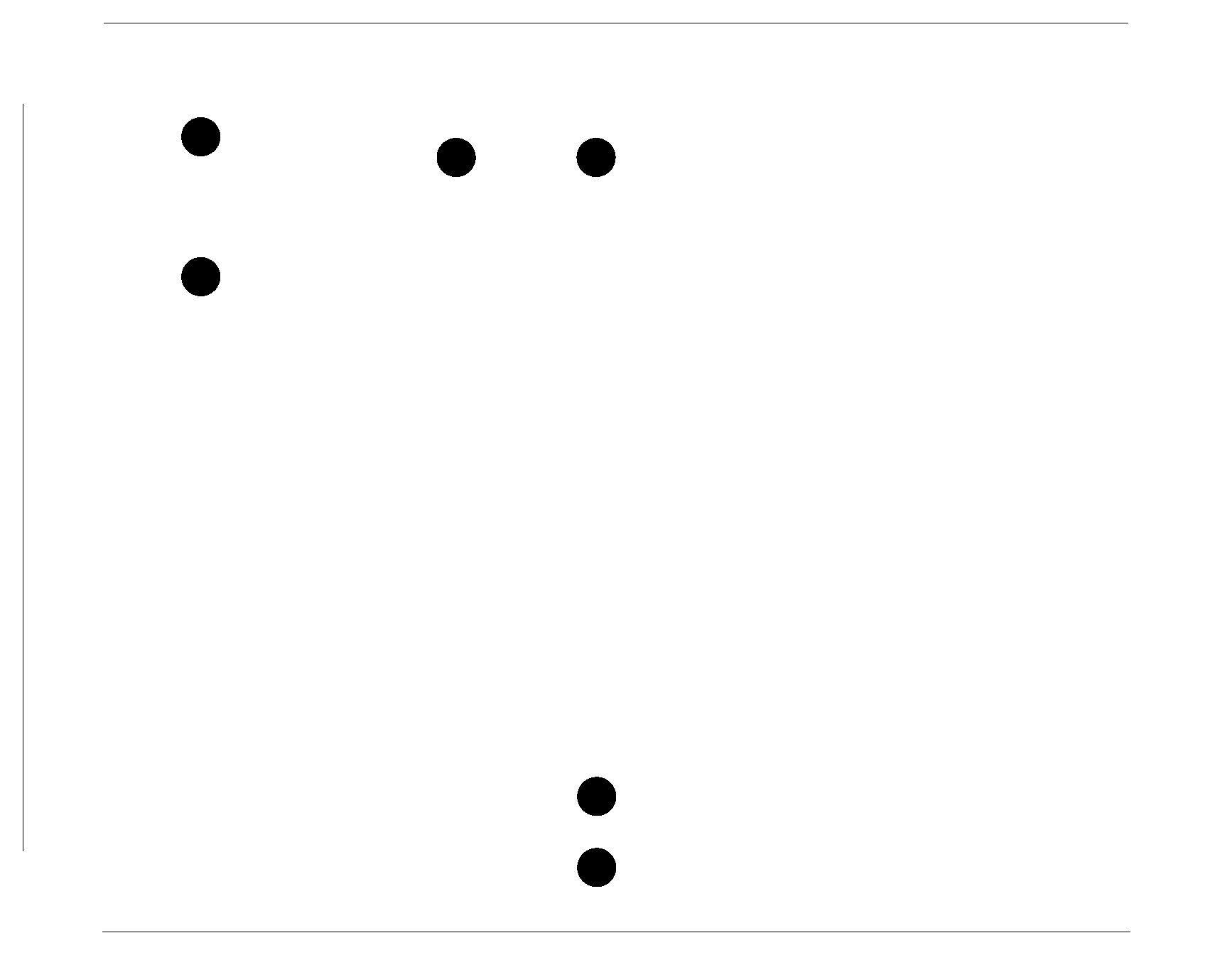
This is the converted gerber files in PNG format.

The rest of the process is the same as before.
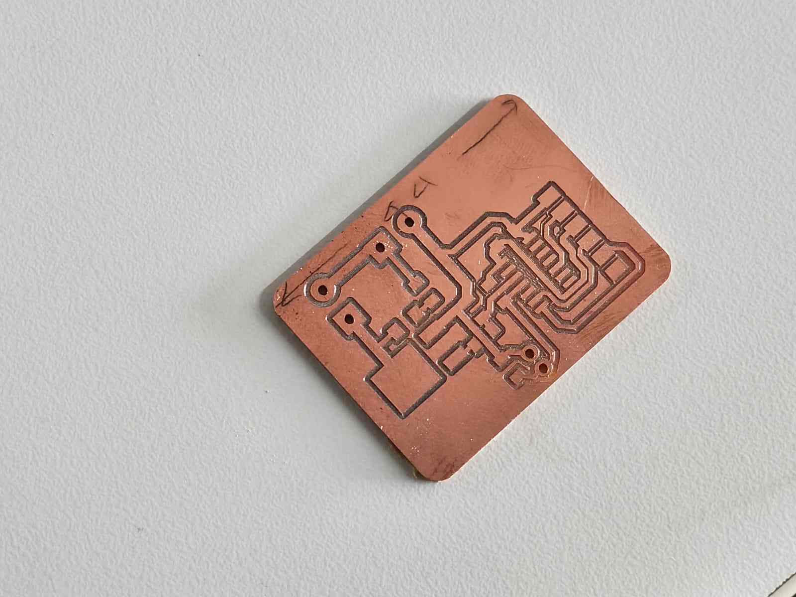
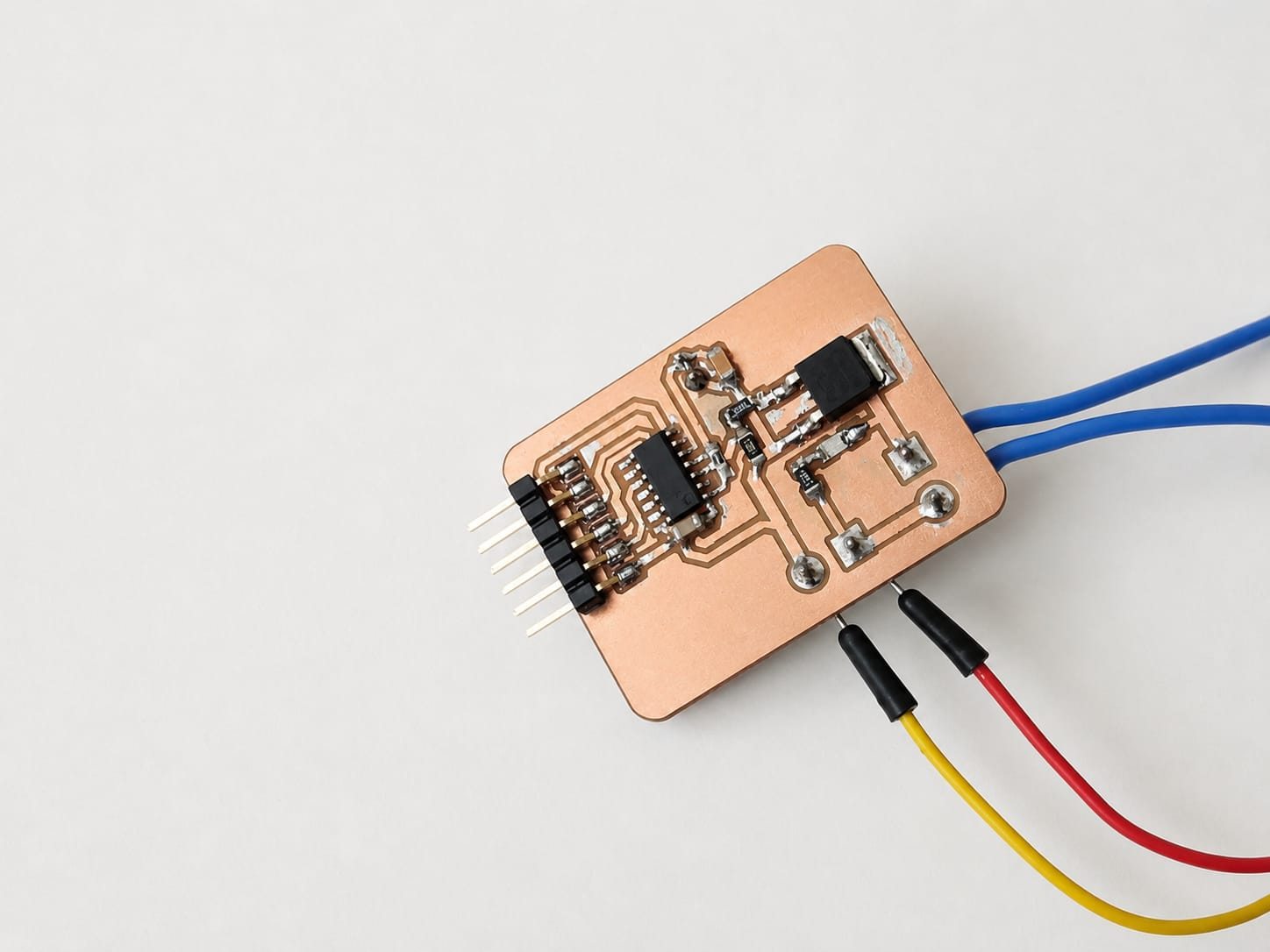
This is my new final PCB after milling.
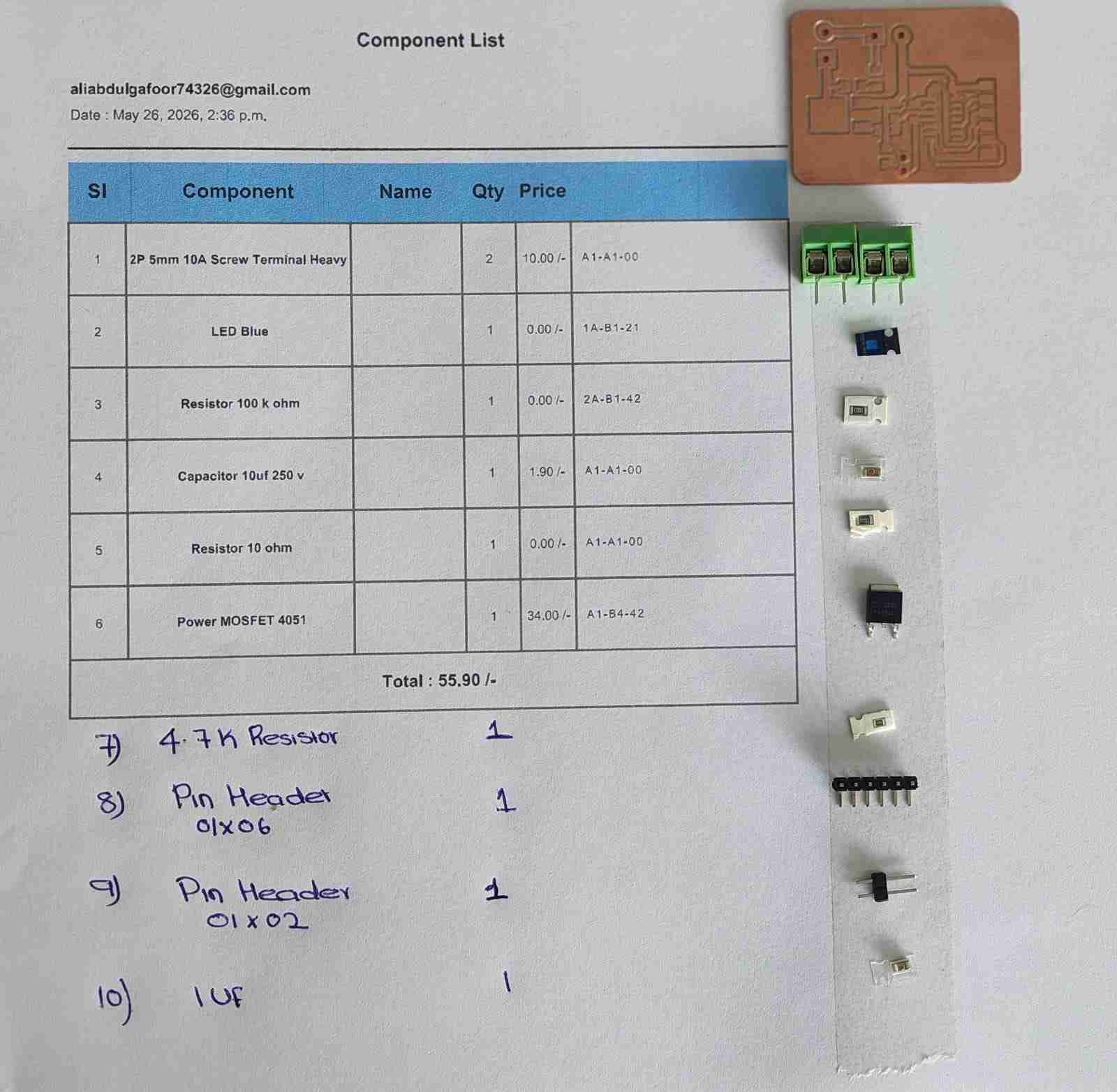
These are the components I took for the new PCB, and the ATtiny1624 I desoldered from my old PCB.
This is the new PCB after soldering.
This is the code I used for testing the new PCB.
/*
  Thermistor + PTC Heater Controller — ATtiny1624 (megaTinyCore)

  Thermistor: VCC → 4.7kΩ → PA6 → Thermistor → GND
  Heater:     PA5 → N-channel MOSFET gate → PTC heater

  State machine:
    HEATING     → heater full ON until temp ≥ 60 °C
    MAINTAINING → bang-bang ±0.5 °C for 3 minutes
    COOLING     → heater OFF, returns to room temp
*/

#include <math.h>

// ── Pins ──────────────────────────────────────────────────────────────────────
#define THERM_PIN   PIN_PA6
#define HEATER_PIN  PIN_PA5

// ── Circuit constants ─────────────────────────────────────────────────────────
const float VCC     = 5.0;
const float R_FIXED = 4700.0;

// ── Thermistor (Beta equation) ────────────────────────────────────────────────
const float BETA      = 3950.0;
const float T0_KELVIN = 298.15;   // 25 °C in Kelvin
const float R0        = 100000.0; // 100 kΩ at 25 °C

// ── ADC ───────────────────────────────────────────────────────────────────────
const int   NUM_SAMPLES = 16;
const float ADC_MAX     = 1023.0;

// ── Heater setpoint & hysteresis ─────────────────────────────────────────────
const float TARGET_TEMP = 60.0;   // °C
const float HYST_HIGH   = 60.5;   // turn heater OFF above this
const float HYST_LOW    = 59.5;   // turn heater ON below this

// ── Hold duration ─────────────────────────────────────────────────────────────
const unsigned long HOLD_MS = 3UL * 60UL * 1000UL; // 3 minutes

// ── State machine ─────────────────────────────────────────────────────────────
enum HeaterState { HEATING, MAINTAINING, COOLING };
HeaterState state = HEATING;
unsigned long holdStart = 0;

// ─────────────────────────────────────────────────────────────────────────────
void setup() {
  Serial.begin(115200);

  pinMode(HEATER_PIN, OUTPUT);
  digitalWrite(HEATER_PIN, LOW);  // safe start — heater off

  analogReference(VDD);
  analogReadResolution(10);

  delay(2000);
  Serial.println("Heater Controller — ATtiny1624");
  Serial.println("Target: 60 C  |  Hold: 3 minutes");
  Serial.println("------------------------------------");

  // Begin heating immediately
  digitalWrite(HEATER_PIN, HIGH);
  Serial.println("[STATE] HEATING");
}

// ── ADC helpers ───────────────────────────────────────────────────────────────
float readVoltage() {
  long sum = 0;
  for (int i = 0; i < NUM_SAMPLES; i++) {
    sum += analogRead(THERM_PIN);
    delay(2);
  }
  return (sum / (float)NUM_SAMPLES / ADC_MAX) * VCC;
}

float voltageToResistance(float v) {
  if (v <= 0.0 || v >= VCC) return -1.0;   // open / short fault
  return R_FIXED * v / (VCC - v);
}

float resistanceToCelsius(float r) {
  if (r <= 0) return NAN;
  float invT = (1.0 / T0_KELVIN) + (1.0 / BETA) * log(r / R0);
  return (1.0 / invT) - 273.15;
}

// ─────────────────────────────────────────────────────────────────────────────
void loop() {
  float voltage    = readVoltage();
  float resistance = voltageToResistance(voltage);
  float tempC      = resistanceToCelsius(resistance);

  if (isnan(tempC) || resistance < 0) {
    digitalWrite(HEATER_PIN, LOW);
    Serial.println("ERROR: Sensor fault — heater OFF for safety");
    delay(1000);
    return;
  }

  switch (state) {

    case HEATING:
      digitalWrite(HEATER_PIN, HIGH);
      if (tempC >= TARGET_TEMP) {
        holdStart = millis();
        state = MAINTAINING;
        Serial.println("[STATE] MAINTAINING");
      }
      break;

    case MAINTAINING: {
      if (tempC >= HYST_HIGH) {
        digitalWrite(HEATER_PIN, LOW);
      } else if (tempC <= HYST_LOW) {
        digitalWrite(HEATER_PIN, HIGH);
      }
      if (millis() - holdStart >= HOLD_MS) {
        digitalWrite(HEATER_PIN, LOW);
        state = COOLING;
        Serial.println("[STATE] COOLING — heater OFF");
      }
      break;
    }

    case COOLING:
      digitalWrite(HEATER_PIN, LOW);
      break;
  }

  Serial.print("Temp: ");
  Serial.print(tempC, 1);
  Serial.print(" C  |  R: ");
  Serial.print(resistance / 1000.0, 2);
  Serial.print(" kOhm  |  V: ");
  Serial.print(voltage, 3);
  Serial.print(" V  |  Heater: ");
  Serial.print(digitalRead(HEATER_PIN) ? "ON " : "OFF");
  Serial.print("  |  State: ");

  switch (state) {
    case HEATING:     Serial.print("HEATING    "); break;
    case MAINTAINING: {
      unsigned long secs = (HOLD_MS - (millis() - holdStart)) / 1000;
      Serial.print("MAINTAIN  ");
      Serial.print(secs / 60);
      Serial.print("m ");
      Serial.print(secs % 60);
      Serial.print("s left");
      break;
    }
    case COOLING:     Serial.print("COOLING    "); break;
  }
  Serial.println();

  delay(1000);
}
This code was made with Claude AI. Below is the prompt I used to generate this code.
i have designed and milled a pcb. this pcb consists of 1 thermistor and 1 ptc heater. and i am using attiny 1624 ic for this pcb. i connected thermistor in PA6 using this code:

/*
  Thermistor Reader — ATtiny1624 (megaTinyCore)
  Circuit: VCC → 4.7kΩ → PA7 (AIN7) → Thermistor → GND
  ⚠ USART0 remapped via Serial.swap(1):
      TX → PA1  (connect to USB-Serial adapter)
      RX → PA2  (unused)
  This frees PA7 from its default USART0-RX role.
*/
#include <math.h>
#define THERM_PIN   PIN_PA6
const float VCC       = 5;
const float R_FIXED   = 4700.0;
const float BETA      = 3950.0;
const float T0_KELVIN = 298.15;
const float R0        = 100000.0;
const int   NUM_SAMPLES = 16;
const float ADC_MAX   = 1023.0;
void setup() {
  Serial.begin(115200);
  analogReference(VDD);
  analogReadResolution(10);
  delay(2000);
  Serial.println("Thermistor Reader - ATtiny1624");
  Serial.println("--------------------------------");
}
float readVoltage() {
  long sum = 0;
  for (int i = 0; i < NUM_SAMPLES; i++) {
    sum += analogRead(THERM_PIN);
    delay(2);
  }
  float raw = sum / (float)NUM_SAMPLES;
  return (raw / ADC_MAX) * VCC;
}
float voltageToResistance(float v) {
  if (v <= 0.0 || v >= VCC) return -1;
  return R_FIXED * v / (VCC - v);
}
float resistanceToCelsius(float r) {
  if (r <= 0) return NAN;
  float invT = (1.0 / T0_KELVIN) + (1.0 / BETA) * log(r / R0);
  return (1.0 / invT) - 273.15;
}
void loop() {
  float voltage    = readVoltage();
  float resistance = voltageToResistance(voltage);
  float tempC      = resistanceToCelsius(resistance);
  float tempF      = tempC * 9.0 / 5.0 + 32.0;
  if (isnan(tempC) || resistance < 0) {
    Serial.println("ERROR: Sensor fault - check wiring");
  } else {
    Serial.print("Temp: ");
    Serial.print(tempC, 1);
    Serial.print(" C  /  ");
    Serial.print(tempF, 1);
    Serial.print(" F    |  R_th: ");
    Serial.print(resistance / 1000.0, 2);
    Serial.print(" kOhm    |  V_adc: ");
    Serial.print(voltage, 3);
    Serial.println(" V");
  }
  delay(1000);
}

This code works perfectly, no error. So next I need to connect heater to PA5 pin along with N-channel MOSFET. I need to make the heater reach 60 degrees Celsius. Heater needs to turn up to 60 degrees and continue at 60 degrees, and after 3 minutes turn off back to room temperature.
While testing, I taped both the heater and thermistor with heat-resistant tape.
Conclusion
I tried 2 PCBs — one in the output week with a vibration motor and OLED display. After that, at the time of the final project, I tried a new PCB with both input and output and got the result I needed.
Useful Links
-
For reference on OLED interfacing and implementation, I visited Saheen FAB – Week 12 Documentation .
-
To understand vibration motor implementation and circuit design, I referred to the documentation by Silvia Palazzi – FAB Academy Week 10 (Output Devices) .
Tools & Technologies Used
The programming for this project was developed using Arduino IDE.
The PCB for this project was designed using KiCad, an open-source electronic design automation (EDA) tool.
AI tools such as ChatGPT were used to assist in generating code, debugging, and improving documentation.
Download Files
- Download Schematic – New Schematic
- Download ZIP File
- Gerber ZIP File