Output Devices
week 12 assignment is to add an output device to a microcontroller board I've designed, and program it to do something
Like I planned before I'll be continuing my Tachometer project which started during my input week,This week of output devices I'm adding an OLED Display device to the PCB that I already made.
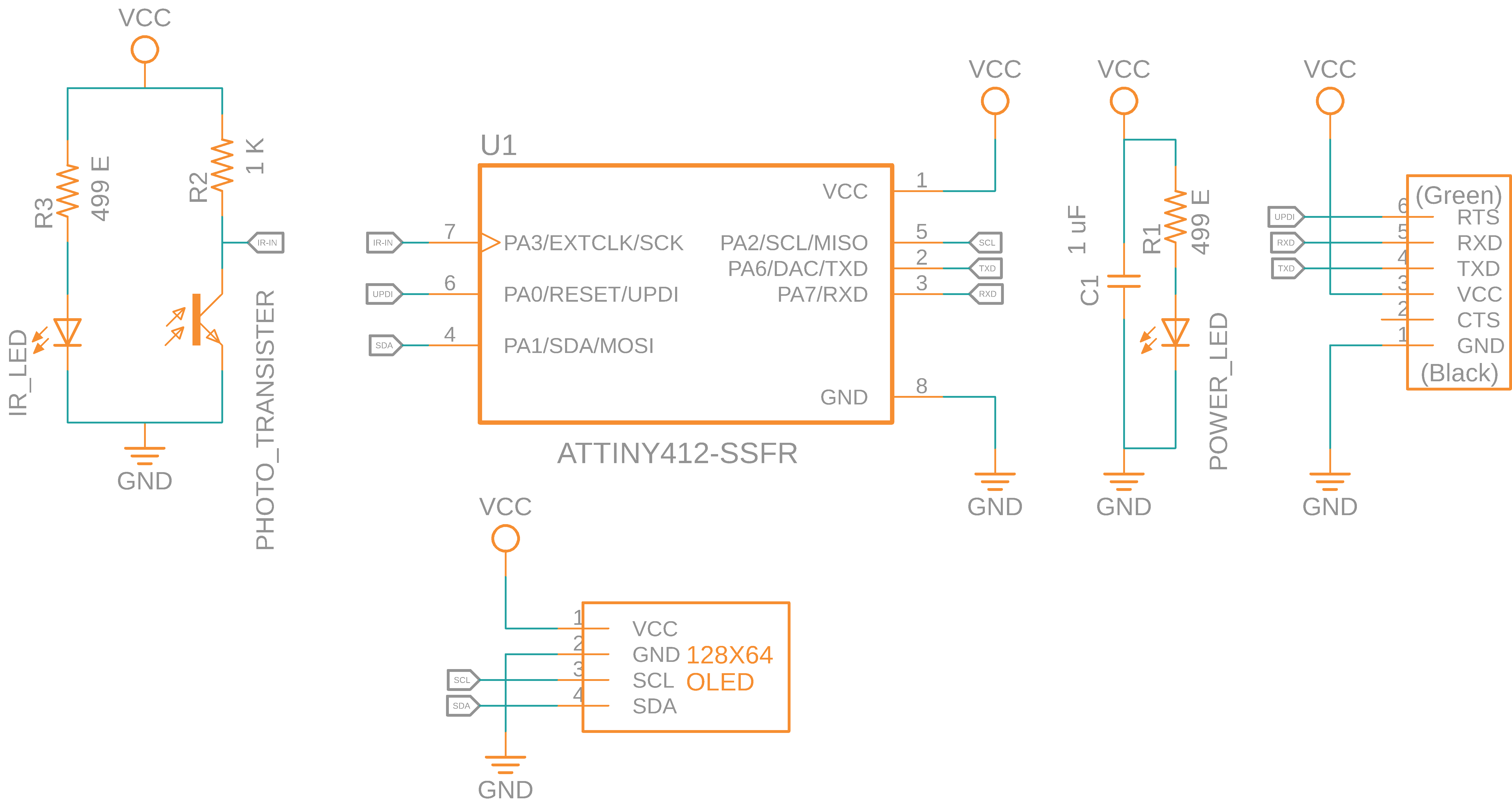
This is the schematic of the board that I already Design
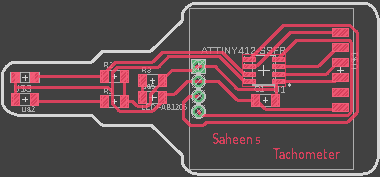
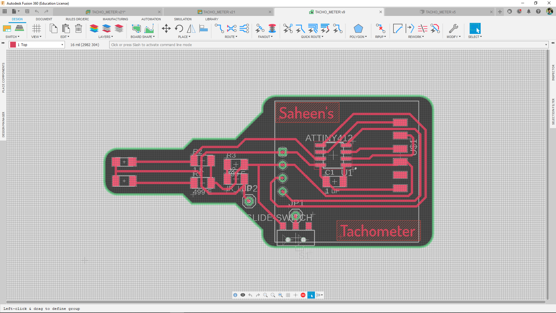
And this is the board layout
Check my Input Devices week to know how I designed the board and how did I added the input sensor and all
OLED Display
An OLED Displays are a Type of Display technology which use Organic Light Emitting Diode for each Individual pixel
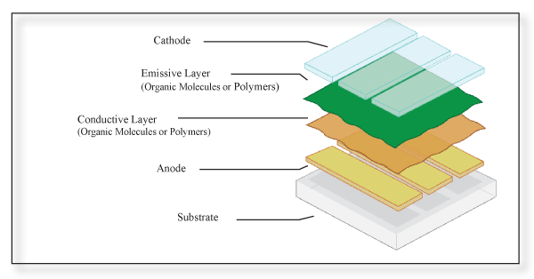
The above Diagram is shows a Physical OLED Structure.This is a modern achievement in Display technologies that finlay we can create almost true black or dark colours while displaying pictures. Because,The main advantage of OLED Displays are we do n't need a huge backlight to power up the entire display .each individual pixel light up itself .
There are many different type of OLED displays module Available in the market
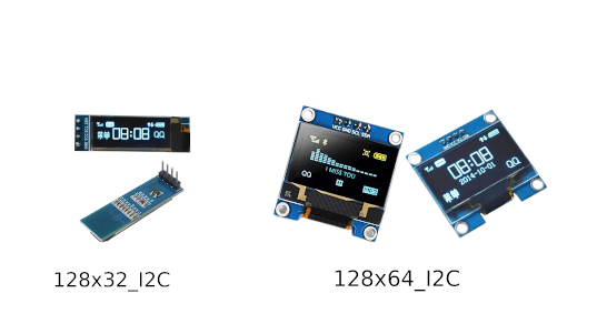
These are the commonly use for prototyping purpose.These type of Module have I2C Protocol to communicate with it.Fablab Kerala has one of these in it's Inventory stock.It's a 0.96" I2C yelLow Blue color OLED Display
I2C Protocol
The Inter Integrated Circuits AKA the IIC or the I2C is a two wire serial Interface communication Protocol just like USB in our Computers.It can communicate between almost upto 128(112) devices when using 7 bits addressing and almost upto 1024(1008)devices when using the 8 bits addressing.
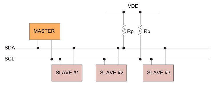
From the figure You can see mainly 2 wires used.one is SDA or Serial Data and other one is SCL Serial Clock
The OLED That I have is using the I2C protocol to receive data for displaying on it.I will do more documentation about I2C in upcoming Networking and communication week. for more checkout the documentation from Howtomechatronics.com
Testing
the Fabrication and design of the my PCB is already done during the Input Devices week,so I can connect the OLED module then start programing.The OLED that I'm Using was based on SSD1306 chip which support both SPI and ISP
Then I edited the OLED Hello world program from Professor Neil ,found on fab output devices class page for the Attiny412 chip with the help of it's data sheet
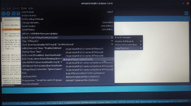
I loaded the code into the arduino IDE and selected the chip Attiny412,port,programmer etc...
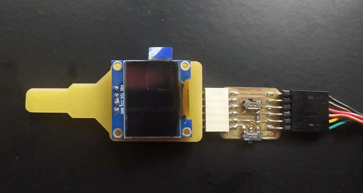
I inserted the OLED Display in place on the PCB and connected to the UPDI board That I made then connected the FTDI cable and finally to my PC.I didn't soldered those pins of OLED,It still get contact because I used copper revet for the Through holes
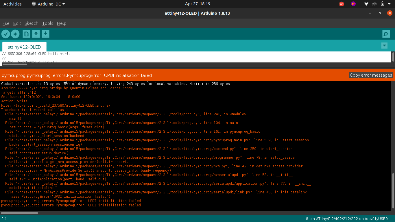
I got an unexpected error!.It was an Upload error.I did programed the board before during the input week.I tried to debug the board and the software,USB plugs..etc.. at last I found out the problem.
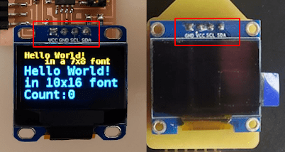
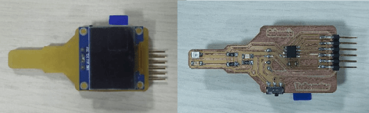
Look at this picture the OLED Pins order is different the left one is Neil's Board and the right one is from our LAB.I was following Neil's board while designing the PCB.Now I have to either redesign the PCb or have to buy a new OLED Module with correct pin order.
After removing the OLED I tried to program the IC again because I can wire the OLED to my board by soldering.But the board not responding! That was strange! and unbelievable .The OLED PIn order mistakes some how course damaged the Attiny412 Chip.
With Arduino
I has to replace the chip in order to continue but because of the Covid 19 protocols I can't access the lab these days.So I'm at home,but have some components with me not the Attiny412 .So I did tested the OLED with an Arduino UNO board
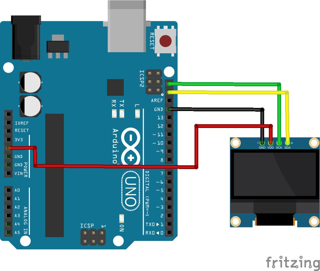
I connected the OLED Display module to the Arduino UNO development board like in the picture.with few jumper wires the hardware very simple!
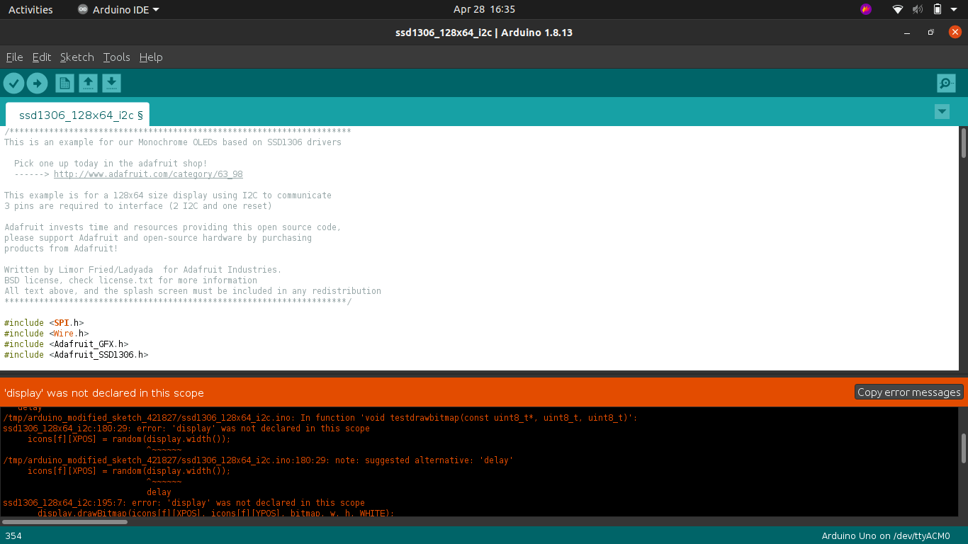
I couldn't edit the Neil's c file for the Atmega328p chip on the Arduino UNO,so I followed the suggested Adafruit library for the SSD1306 OLED Modules.found trouble while programing
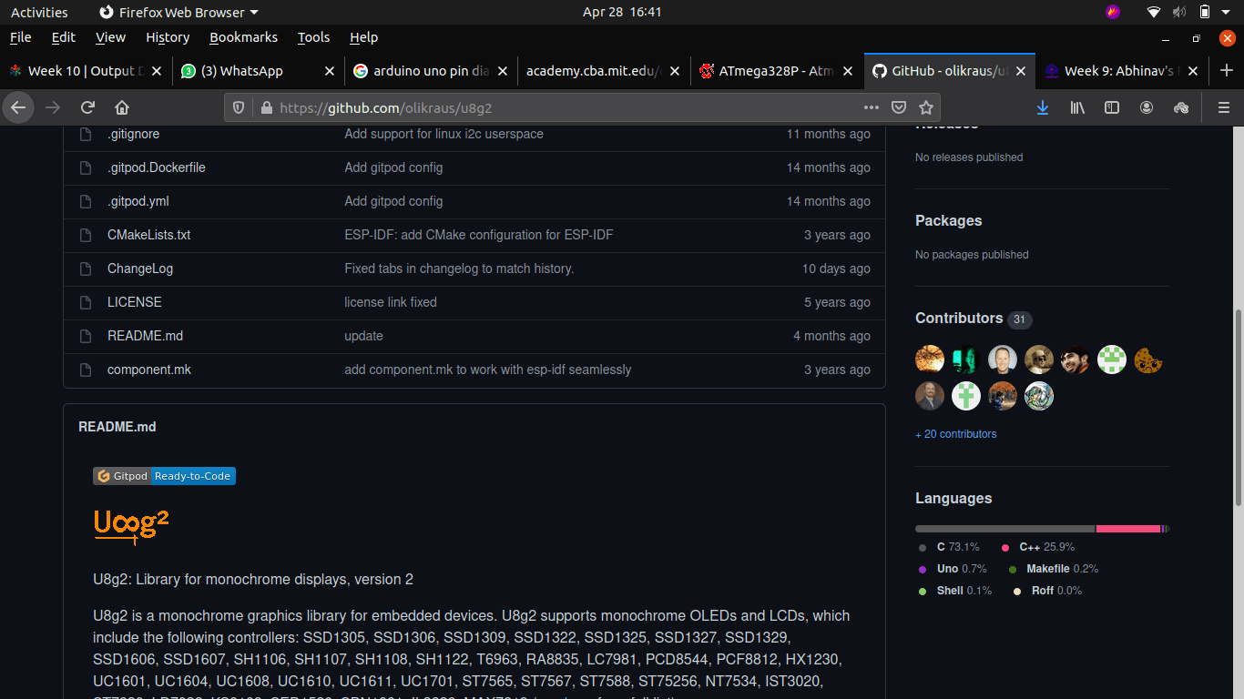
with little bit of research and some effort I found another library for the OLED called u8g2 from Github/olikraus .still got trouble while adding the zipp libary to the arduino,but I mangged to clear the trouble here is the simplified and easy to install version of the u8g2 by me
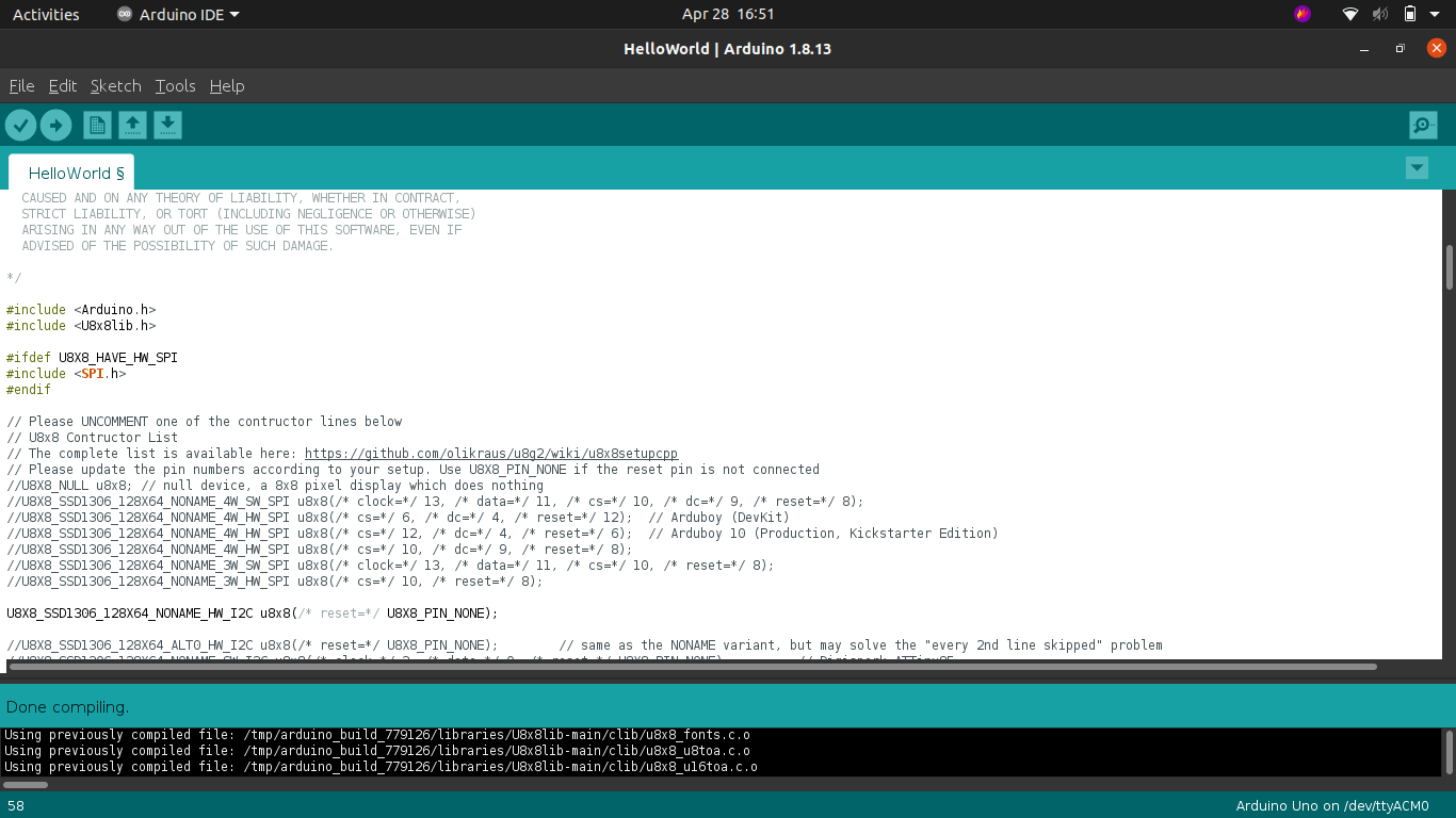
after adding the zip library to the arduino ide I loaded the hello world program for the OLED by following File >>Examples >>U8x8lib >>HelloWorld
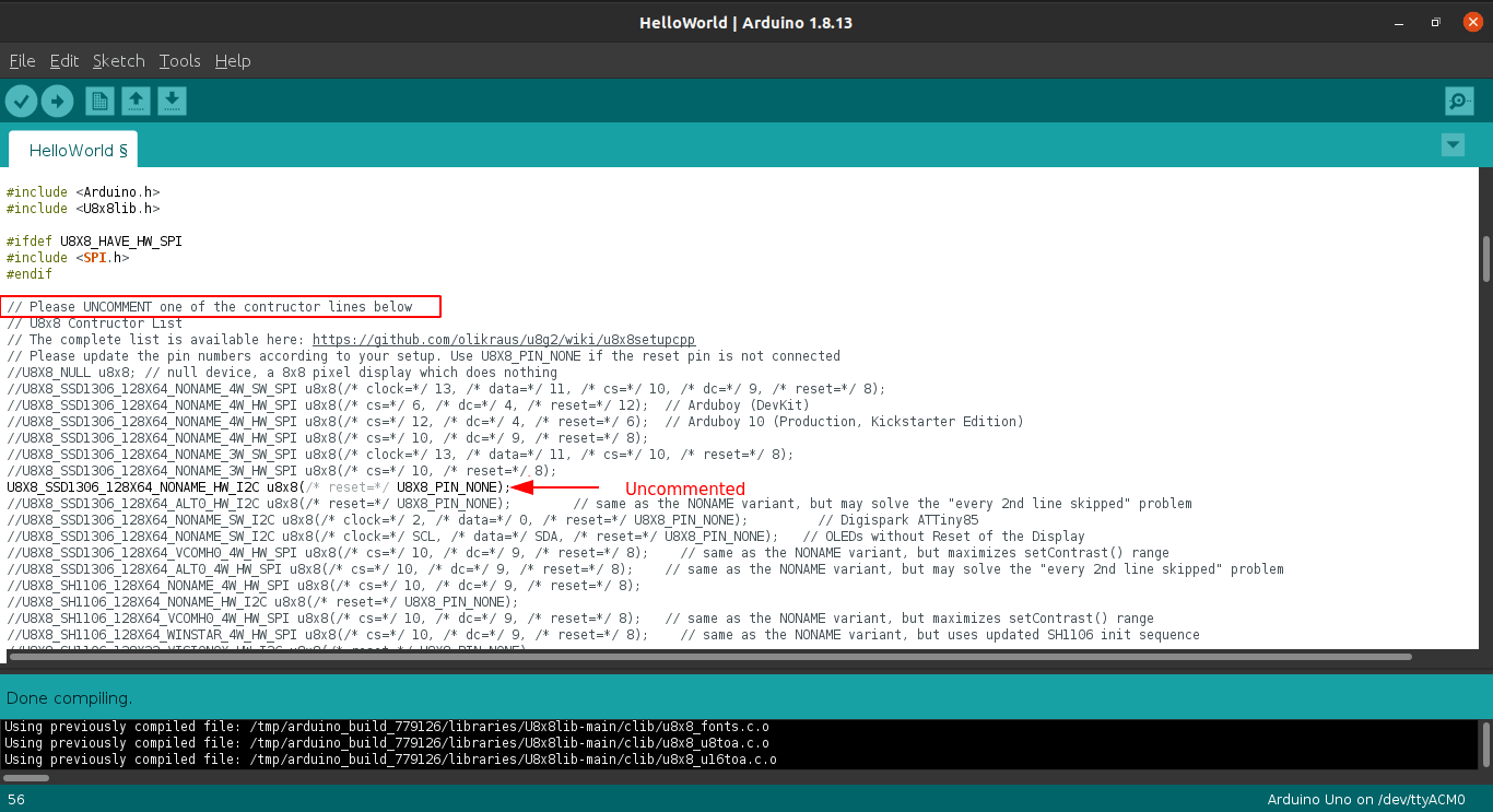
As per the instructions I uncomment the line for selecting the OLED display type and compiled successfully
Then I plugged the arduino uno board and selected the board, as well as the port then uploaded the sketch
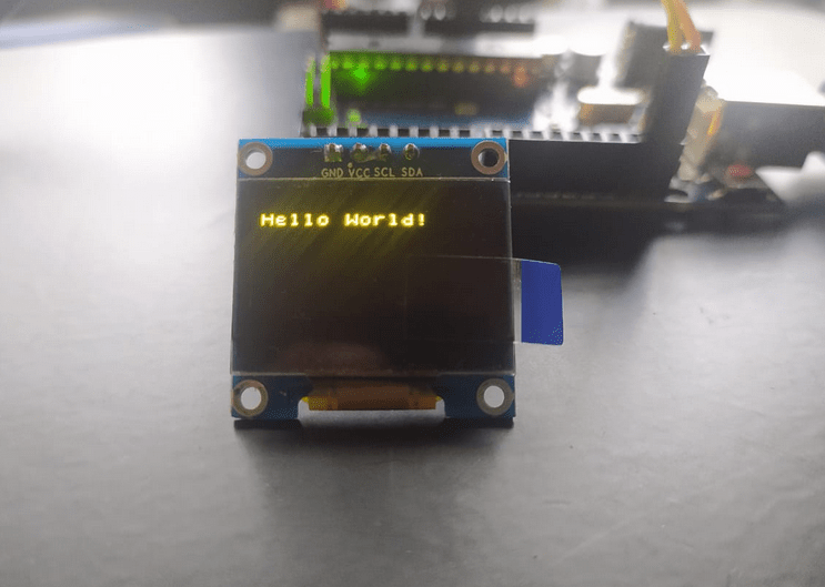
It's working!.This is not my first time with the OLED module I worked with 0.91" IIC 128x32 type module before
Re-Designing
After the covid lock-down, I return to the LAB and Continue the assignment by redesigning the Board by correcting the mistakes that I found
The RXD TXD connections in the previouse board was not really oky it was twisted so I switch them in between to make it right
Here is the design of board looks like . you can see I also added a slide switch and battery terminals to turn on and off the power of the entire board If I make it battery powered device.
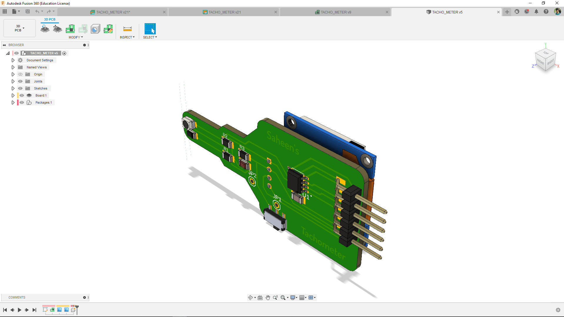
Also completed the 3D model of the PCB to create the enclosure in fusion's product designing techniques
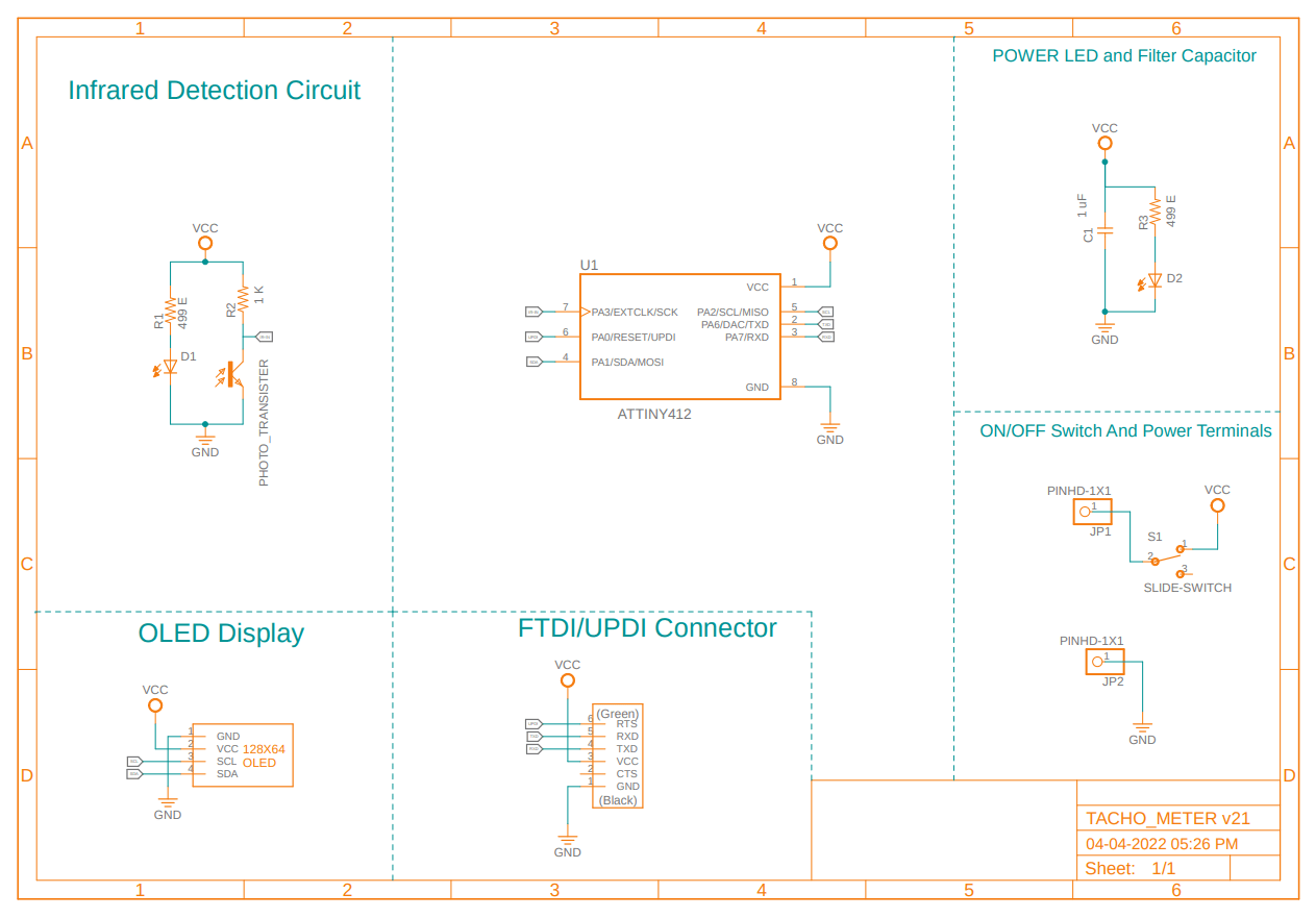
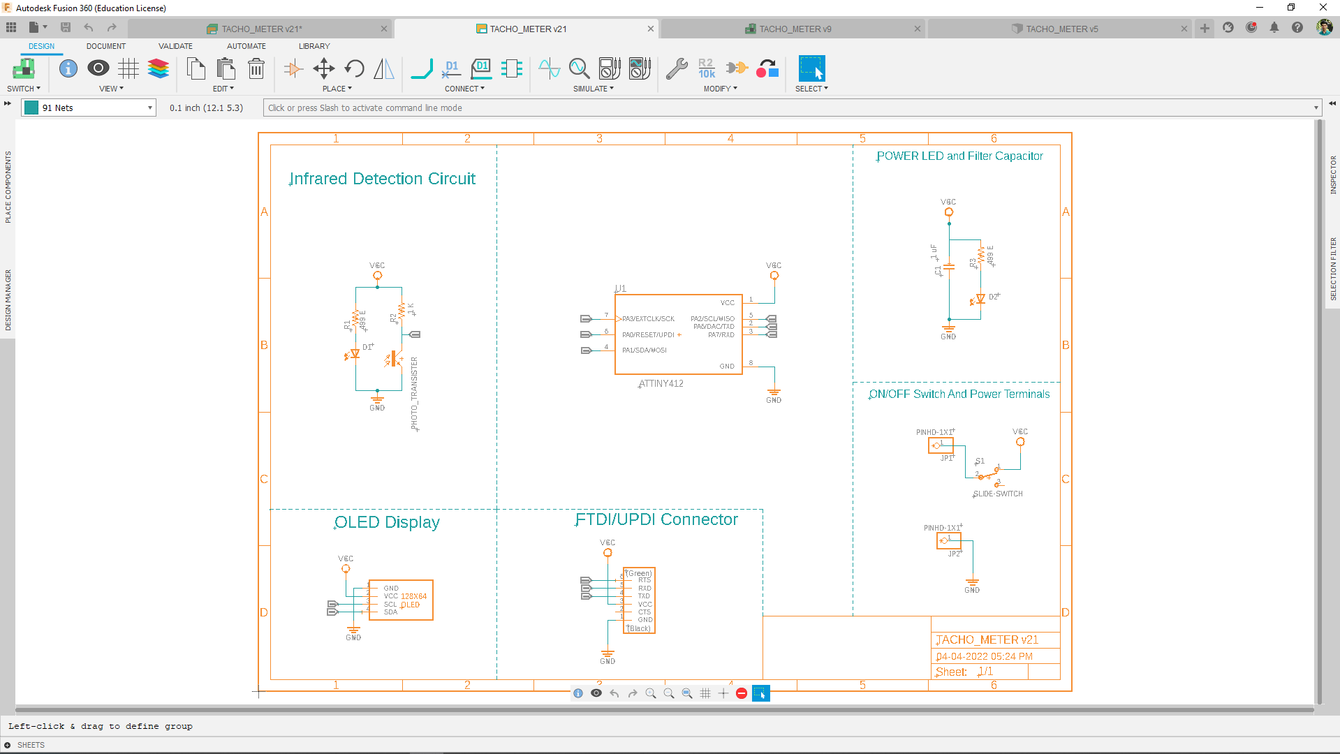
Here is the final schematic diagram of the tachometer also organized for better understanding the Circuit.
Then I Milled out the board and soldered everything in place with new components and also soldered the OLED display in the board.
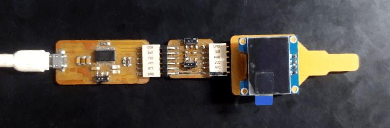
Here is the new programing setup that I use and that's right I did make my own USb to Serial COnverter using FT232R FTDI chip.
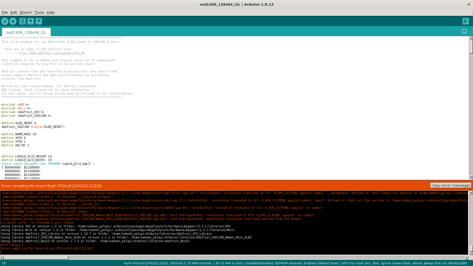
Then I tried to program the board to make the OLED running using the attiny412 turns out the U8x8lib is not compatible with Attiny412 and I've also tried the Adafruit SSD1306 library example but I thing the size is too large for the flash memmory of the Attiny412 chip.
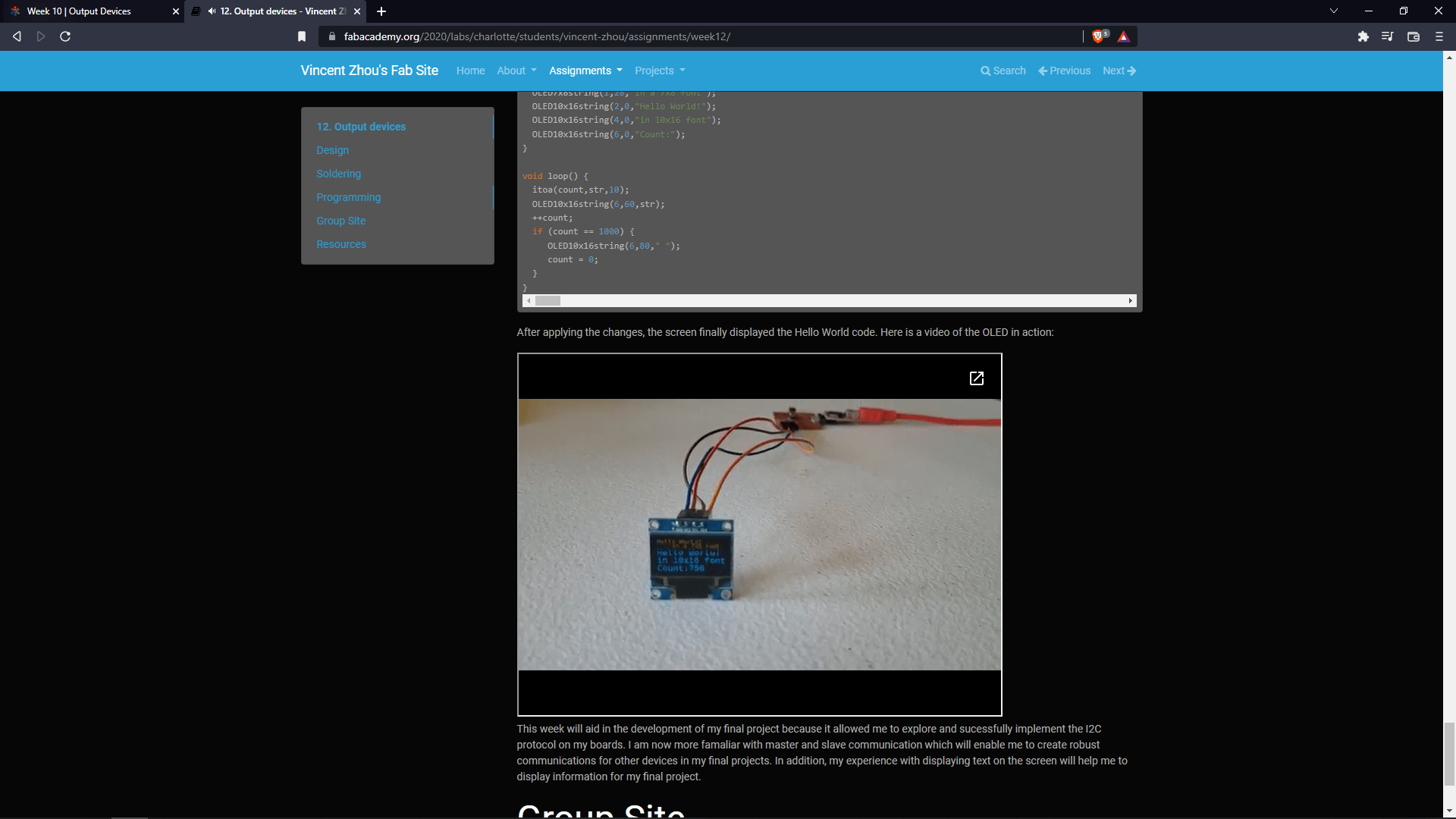
By doing some digging in the fab documentations of previous students I found out This output week documentation by a guy named Vincent Zhou has same problems I did and he solved the problem by modifying Neil's OLED code for Attiny45 and he got succeed!
CODE :-
        #include < avr/io.h>
        #include < util/delay.h>
        #include < avr/pgmspace.h>
        #include < stdlib.h>

        #define I2C_slave_address 0x78
        #define I2C_delay() _delay_us(5)

        #define TWI0_BAUD(F_SCL)      ((((float)F_CPU / (float)F_SCL)) - 10 )
        void TWI_init()
        {
          TWI0.MBAUD = (uint8_t)TWI0_BAUD(100000);  // Set MBAUD register for 100kHz
          TWI0.MCTRLA = 1 << TWI_ENABLE_bp          // Enable TWI Master: enabled
          | 0 << TWI_QCEN_bp                        // Quick Command Enable: disabled
          | 0 << TWI_RIEN_bp                        // Read Interrupt Enable: disabled
          | 1 << TWI_SMEN_bp                        // Smart Mode Enable: enabled
          | TWI_TIMEOUT_DISABLED_gc                 // Bus Timeout Disabled
          | 0 << TWI_WIEN_bp;                       // Write Interrupt Enable: disabled

          TWI0.MCTRLB |= TWI_FLUSH_bm;              // Purge MADDR and MDATA
          TWI0.MSTATUS |= TWI_BUSSTATE_IDLE_gc;     // Force TWI state machine into IDLE state
          TWI0.MSTATUS |= (TWI_RIF_bm | TWI_WIF_bm);
        }

        uint8_t TWI_start(uint8_t deviceAddr)
        {
          if ((TWI0.MSTATUS & TWI_BUSSTATE_gm) != TWI_BUSSTATE_BUSY_gc)   //Verify Bus is not busy
          {
            TWI0.MCTRLB &= ~(1 << TWI_ACKACT_bp);
            TWI0.MADDR = deviceAddr ;
            if (deviceAddr&0x01)  {while(!(TWI0.MSTATUS & TWI_RIF_bm));}  // If addressRead
            else                  {while(!(TWI0.MSTATUS & TWI_WIF_bm));}  // If addressWrite
            return 0;
          }
          else return 1;                                                  // Bus is busy
        }

        uint8_t TWI_read(uint8_t ACK)                                     // ACK=1 send ACK ; ACK=0 send NACK
        {

          if ((TWI0.MSTATUS & TWI_BUSSTATE_gm) == TWI_BUSSTATE_OWNER_gc)  // Verify Master owns the bus
          {
            while(!(TWI0.MSTATUS & TWI_RIF_bm));                          // Wait until RIF set
            uint8_t data=TWI0.MDATA;
            if(ACK==1)  {TWI0.MCTRLB &= ~(1< action send ack
            else        {TWI0.MCTRLB |= (1< put 1 ACKACT => nack prepared for actionstop

            return data ;
          }
          else
          return 1; //Master does not own the bus

        }
        uint8_t TWI_write(uint8_t write_data)
        {
          if ((TWI0.MSTATUS&TWI_BUSSTATE_gm) == TWI_BUSSTATE_OWNER_gc)              // Verify Master owns the bus
          {
            TWI0.MDATA = write_data;
            while (!((TWI0.MSTATUS & TWI_WIF_bm) | (TWI0.MSTATUS & TWI_RXACK_bm))); // Wait until WIF set and RXACK cleared
            return 0;
          }
          else
          return 1;                                                                 // Master does not own the bus
        }

        void TWI_stop(void)
        {
          TWI0.MCTRLB |= TWI_ACKACT_NACK_gc;
          TWI0.MCTRLB |= TWI_MCMD_STOP_gc;
        }

        // This function is central to I2C communications. Normal pin setting is replaced with TWI functions.
        char TWI_master_write(unsigned char* data,unsigned char nbytes,unsigned char slave_address)
        {
          unsigned char index, ret, slave_address_write;

          // Send start and send slave address
          slave_address_write = slave_address << 1;
          if (TWI_start(slave_address) != 0)
            // No ACK,return 1
            return 1;

          // Loop over bytes
          for (index = 0; index < nbytes; ++index) {
            ret = TWI_write((data[index]));
            if (ret != 0)
               // No ACK, return 1
               break;
            // Yes ACK, continue
          }

          //Send stop
          TWI_stop();
          return ret;
        }

        static const uint8_t MonospaceBold7x8[] PROGMEM = {0,0,0,0,0,0,0,0,0,0,223,223,0,0,0,0,7,0,7,0,0,32,228,62,231,124,39,4,0,76,154,255,154,112,0,39,37,23,232,168,228,0,0,112,247,159,241,192,240,0,0,0,7,0,0,0,0,0,24,126,195,0,0,0,0,195,126,24,0,0,0,18,12,63,12,18,0,0,16,16,124,16,16,0,0,128,112,48,0,0,0,0,0,48,48,48,0,0,0,0,192,192,0,0,0,0,0,192,56,6,1,0,0,126,255,129,
                                                            137,255,126,0,129,129,255,255,128,128,0,129,193,161,153,143,134,0,129,137,137,137,247,118,0,48,44,38,255,255,32,0,143,143,137,137,249,113,0,124,255,139,137,249,112,0,1,129,241,125,31,3,0,118,247,137,137,247,118,0,14,159,145,209,255,62,0,0,204,204,0,0,0,0,0,204,204,0,0,0,0,48,48,120,72,72,204,0,40,40,40,40,40,40,0,204,
                                                            72,72,120,48,48,0,2,217,215,7,0,0,124,130,57,69,69,254,0,0,192,252,47,47,252,192,0,255,255,137,137,247,118,0,60,126,195,129,129,66,0,255,255,129,129,255,60,0,255,255,137,137,137,129,0,255,255,9,9,9,1,0,60,126,195,145,241,242,0,255,255,8,8,255,255,0,129,129,255,255,129,129,0,64,128,129,129,255,127,0,255,255,24,62,227,193,
                                                            0,255,255,128,128,128,128,0,255,254,28,28,254,255,0,255,255,14,112,255,255,0,126,255,129,129,255,126,0,255,255,17,17,31,14,0,126,255,129,129,255,126,0,255,255,17,17,111,206,128,78,143,153,153,241,114,0,1,1,255,255,1,1,0,127,255,128,128,255,127,0,3,63,240,240,63,3,15,255,240,12,240,255,15,0,129,231,60,60,231,129,0,1,15,252,
                                                            252,15,1,0,193,225,185,141,135,131,0,0,255,255,129,0,0,0,1,6,56,192,0,0,0,0,129,255,255,0,0,4,6,3,3,6,4,0,128,128,128,128,128,128,128,0,1,3,2,0,0,0,0,96,244,148,148,252,248,0,255,255,136,136,248,112,0,120,252,204,132,132,132,0,112,248,136,136,255,255,0,120,252,148,148,156,152,0,8,254,255,9,9,0,0,28,190,162,162,254,126,0,255,
                                                            255,8,8,248,240,0,136,136,251,251,128,128,0,136,136,251,123,0,0,0,255,255,16,124,196,128,1,1,127,255,128,128,0,0,252,252,4,252,4,252,0,252,252,4,4,252,248,0,120,252,132,132,252,120,0,254,254,34,34,62,28,0,28,62,34,34,254,254,0,0,252,252,4,4,4,0,88,156,180,180,228,104,4,4,255,255,132,132,0,0,124,252,128,128,252,252,0,12,124,224,
                                                            224,124,12,12,252,224,16,224,252,12,0,132,204,120,120,204,132,0,130,142,248,56,14,2,0,196,228,164,148,156,140,0,16,16,239,239,129,129,0,0,0,255,0,0,0,0,129,129,239,239,16,16,0,16,16,16,32,32,32};

        static const uint8_t MonospaceBold10x16lo[] PROGMEM = {0,0,0,0,0,0,0,0,0,0,0,0,0,0,254,254,0,0,0,0,0,0,30,30,0,0,30,30,0,0,0,48,176,248,62,50,240,254,62,48,0,112,248,216,254,152,152,0,0,0,28,34,162,162,156,64,64,32,32,0,0,0,220,126,230,198,134,12,128,128,0,0,0,0,30,30,0,0,0,0,0,0,0,224,252,30,2,0,0,0,0,0,2,30,252,224,0,0,0,0,0,72,120,48,254,48,120,72,0,0,0,128,128,128,240,240,128,128,
                                                                128,0,0,0,0,0,0,0,0,0,0,0,0,0,0,0,0,0,0,0,0,0,0,0,0,0,0,0,0,0,0,0,0,0,0,0,192,240,60,14,2,0,0,240,252,14,198,198,14,252,248,0,0,0,12,6,254,254,0,0,0,0,0,12,6,6,6,134,198,124,56,0,0,12,6,198,198,198,198,252,56,0,0,128,192,112,24,14,254,254,0,0,0,254,126,102,102,102,230,198,128,0,0,240,252,206,102,102,230,204,128,0,0,6,6,6,6,230,254,
                                                                62,14,0,0,56,252,198,198,198,198,252,56,0,0,120,252,206,134,134,206,252,248,0,0,0,0,0,224,224,0,0,0,0,0,0,0,0,224,224,0,0,0,0,0,128,128,192,64,96,96,32,48,0,0,96,96,96,96,96,96,96,96,0,0,48,32,96,96,64,192,128,128,0,0,12,6,134,198,102,126,28,0,0,224,240,56,156,204,204,220,248,240,0,0,0,192,252,62,62,252,192,0,0,0,254,254,198,198,198,
                                                                198,252,60,0,0,240,252,12,6,6,6,6,12,0,0,254,254,6,6,6,12,252,240,0,0,254,254,198,198,198,198,198,6,0,0,254,254,198,198,198,198,198,6,0,0,240,252,12,6,134,134,134,140,0,0,254,254,192,192,192,192,254,254,0,0,0,6,6,254,254,6,6,0,0,0,0,0,0,6,6,6,254,254,0,0,254,254,224,240,252,14,6,2,0,0,254,254,0,0,0,0,0,0,0,0,254,254,62,240,240,62,254,
                                                                254,0,0,254,254,30,240,192,0,254,254,0,0,240,252,14,6,6,14,252,240,0,0,254,254,198,198,198,198,124,124,0,0,240,252,14,6,6,14,252,240,0,0,254,254,198,198,198,198,252,60,0,0,56,124,230,198,198,198,140,0,0,0,6,6,6,254,254,6,6,6,0,0,254,254,0,0,0,0,254,254,0,0,6,254,252,0,0,252,254,6,0,30,254,224,0,240,240,0,224,254,30,0,2,14,62,248,248,62,
                                                                14,2,0,2,14,62,120,224,224,120,62,14,2,0,6,6,134,198,246,126,30,14,0,0,0,0,254,254,2,2,0,0,0,0,2,14,56,224,128,0,0,0,0,0,0,2,2,254,254,0,0,0,0,16,24,28,14,6,14,28,24,16,0,0,0,0,0,0,0,0,0,0,0,0,0,1,3,6,4,0,0,0,0,0,0,96,48,176,176,176,240,224,0,0,254,254,96,48,48,112,224,192,0,0,192,224,112,48,48,48,48,96,0,0,192,224,112,48,48,96,254,254,0,
                                                                0,192,224,176,176,176,176,224,192,0,0,48,48,252,254,54,54,54,0,0,0,192,224,112,48,48,96,240,240,0,0,254,254,96,48,48,48,240,224,0,0,0,48,48,247,247,0,0,0,0,0,0,48,48,247,247,0,0,0,0,0,254,254,128,224,112,48,16,0,0,0,6,6,254,254,0,0,0,0,0,0,240,240,48,240,224,48,240,224,0,0,240,240,96,48,48,48,240,224,0,0,192,224,112,48,48,112,224,192,0,0,
                                                                240,240,96,48,48,112,224,192,0,0,192,224,112,48,48,96,240,240,0,0,0,240,240,96,48,48,48,48,0,0,224,240,176,176,176,176,48,96,0,0,48,48,252,252,48,48,48,0,0,0,240,240,0,0,0,0,240,240,0,0,48,240,224,0,0,224,240,48,0,112,240,0,0,192,192,0,0,240,112,0,16,48,240,192,192,240,48,16,0,0,16,240,240,128,0,240,240,48,0,0,48,48,48,48,176,240,112,48,
                                                                0,0,0,0,0,252,254,2,2,0,0,0,0,0,0,254,254,0,0,0,0,0,0,2,2,254,252,0,0,0,0,0,128,192,192,192,128,128,128,192,0,0,0,0,0};

        static const uint8_t MonospaceBold10x16hi[] PROGMEM = {0,0,0,0,0,0,0,0,0,0,0,0,0,0,25,25,0,0,0,0,0,0,0,0,0,0,0,0,0,0,3,27,31,3,3,31,15,3,3,0,0,12,24,24,127,25,31,15,0,0,1,1,0,0,14,17,17,17,14,0,0,7,15,28,24,25,31,30,31,19,0,0,0,0,0,0,0,0,0,0,0,0,0,7,63,120,64,0,0,0,0,0,64,120,63,7,0,0,0,0,0,0,0,0,1,0,0,0,0,0,0,1,1,1,15,15,1,1,1,0,0,0,0,64,124,60,0,0,0,0,0,0,3,3,3,3,3,0,0,0,0,0,0,0,28,28,0,0,
                                                                0,0,0,32,56,30,7,1,0,0,0,0,0,3,15,28,24,24,28,15,7,0,0,24,24,24,31,31,24,24,24,0,0,24,28,30,27,25,24,24,24,0,0,12,24,24,24,24,25,15,15,0,0,3,3,3,3,3,31,31,3,0,0,12,24,24,24,24,28,15,7,0,0,7,15,28,24,24,28,15,7,0,0,0,16,28,15,3,0,0,0,0,0,15,15,24,24,24,24,15,15,0,0,0,12,25,25,25,28,15,3,0,0,0,0,0,28,28,0,0,0,0,0,0,0,64,124,60,0,0,0,0,0,1,
                                                                1,3,2,6,6,4,12,0,0,6,6,6,6,6,6,6,6,0,0,12,4,6,6,2,3,1,1,0,0,0,0,27,27,0,0,0,0,0,7,31,56,115,103,102,102,119,39,0,0,24,31,15,3,3,15,31,24,0,0,31,31,24,24,24,24,31,15,0,0,3,15,12,24,24,24,24,12,0,0,31,31,24,24,24,12,15,3,0,0,31,31,24,24,24,24,24,24,0,0,31,31,0,0,0,0,0,0,0,0,3,15,12,24,25,25,31,15,0,0,31,31,0,0,0,0,31,31,0,0,0,24,24,31,31,
                                                                24,24,0,0,0,12,24,24,24,24,24,15,15,0,0,31,31,0,0,3,15,30,24,0,0,31,31,24,24,24,24,24,24,0,0,31,31,0,1,1,0,31,31,0,0,31,31,0,0,3,30,31,31,0,0,3,15,28,24,24,28,15,3,0,0,31,31,0,0,0,0,0,0,0,0,3,15,28,24,24,60,111,7,0,0,31,31,0,0,1,3,31,30,16,0,12,24,24,24,24,25,15,15,0,0,0,0,0,31,31,0,0,0,0,0,7,15,28,24,24,28,15,7,0,0,0,0,31,31,31,31,0,0,
                                                                0,0,31,31,30,1,1,30,31,31,0,0,16,28,31,3,3,31,28,16,0,0,0,0,0,31,31,0,0,0,0,0,28,30,31,27,24,24,24,24,0,0,0,0,127,127,64,64,0,0,0,0,0,0,0,0,3,14,56,32,0,0,0,64,64,127,127,0,0,0,0,0,0,0,0,0,0,0,0,0,0,0,0,0,0,0,0,0,0,0,0,0,0,0,0,0,0,0,0,0,0,0,14,31,27,25,25,13,31,31,0,0,31,31,12,24,24,28,15,7,0,0,7,15,28,24,24,24,24,12,0,0,7,15,28,24,24,
                                                                12,31,31,0,0,7,15,29,25,25,25,25,13,0,0,0,0,31,31,0,0,0,0,0,0,7,111,220,216,216,204,255,127,0,0,31,31,0,0,0,0,31,31,0,0,24,24,24,31,31,24,24,24,0,0,192,192,192,255,127,0,0,0,0,0,31,31,1,3,7,30,24,16,0,0,0,0,15,31,24,24,24,0,0,0,31,31,0,31,31,0,31,31,0,0,31,31,0,0,0,0,31,31,0,0,7,15,28,24,24,28,15,7,0,0,255,255,12,24,24,28,15,7,0,0,7,15,
                                                                28,24,24,12,255,255,0,0,0,31,31,0,0,0,0,0,0,0,12,25,25,25,25,27,31,14,0,0,0,0,15,31,24,24,24,0,0,0,15,31,24,24,24,12,31,31,0,0,0,1,15,30,30,15,1,0,0,0,7,31,30,3,3,30,31,7,0,0,16,24,30,7,7,30,24,16,0,0,0,192,195,255,63,15,1,0,0,0,24,28,30,27,25,24,24,24,0,0,0,1,1,126,254,128,128,0,0,0,0,0,0,255,255,0,0,0,0,0,0,128,128,254,126,1,1,0,0,0,1,
                                                                0,0,0,1,1,1,0,0,0,0,0,0};

        void OLEDcommand(uint8_t c) {
          static uint8_t data[2];
          data[0] = 0;
          data[1] = c;
          TWI_master_write(data,2,I2C_slave_address);
        }

        void OLEDcommands(uint8_t c1,uint8_t c2) {
          static uint8_t data[3];
          data[0] = 0;
          data[1] = c1;
          data[2] = c2;
          TWI_master_write(data,3,I2C_slave_address);
        }

        void OLEDdata(uint8_t d) {
          static uint8_t data[2];
          data[0] = 0x40;
          data[1] = d;
          TWI_master_write(data,2,I2C_slave_address);
        }

        void OLED7x8string(uint8_t row,uint8_t col,char str[]) {
          static uint8_t index,offset,pointer;
          static char chr;
          OLEDcommands(0x00+(col & 0x0F),0x10+((col >> 4) & 0x0F));
          OLEDcommand(0xB0+row);
          index = 0;
          while (1) {
            chr = str[index];
            if (chr == '\0') break;
            pointer = chr-' ';
            for (offset = 0; offset < 7; ++offset) {
               OLEDdata(pgm_read_byte(&(MonospaceBold7x8[7*pointer+offset])));
            }
            ++index;
          }
        }

        void OLED10x16string(uint8_t row,uint8_t col,char str[]) {
          static uint8_t index,offset,pointer;
          static char chr;
          OLEDcommands(0x00+(col & 0x0F),0x10+((col >> 4) & 0x0F));
          OLEDcommand(0xB0+row);
          index = 0;
          while (1) {
            chr = str[index];
            if (chr == '\0') break;
            pointer = chr-' ';
            for (offset = 0; offset < 10; ++offset) {
               OLEDdata(pgm_read_byte(&(MonospaceBold10x16lo[10*pointer+offset])));
            }
            ++index;
          }
          OLEDcommands(0x00+(col & 0x0F),0x10+((col >> 4) & 0x0F));
          OLEDcommand(0xB0+row+1);
          index = 0;
          while (1) {
            chr = str[index];
            if (chr == '\0') break;
            pointer = chr-' ';
            for (offset = 0; offset < 10; ++offset) {
               OLEDdata(pgm_read_byte(&(MonospaceBold10x16hi[10*pointer+offset])));
            }
            ++index;
            }
          }
        void OLED128x64init() {
          uint8_t i,j;
          //Init TWI
          TWI_init();

          //Init SSD1306
          OLEDcommand(0xae);       // Display off
          OLEDcommands(0xa8,0x3f); // Set multiplex ratio, ratio 63
          OLEDcommands(0xd3,0x00); // Set display offset, no offset
          OLEDcommand(0x40);       // Set display start line
          OLEDcommand(0xa1);       // Set segment remap col 127 to seg 0
          OLEDcommand(0xc8);       // Set COM output reverse
          OLEDcommands(0xda,0x12); // COM pin config, alt bottom to top
          OLEDcommands(0x81,0xff); // Set contrast, max contrast
          OLEDcommand(0xa4);       // Resume to RAM display
          OLEDcommand(0xa6);       // Normal non-inverted display
          OLEDcommands(0xd5,0x80); // Set clock divider, default
          OLEDcommands(0x8d,0x14); // Set charge pump, enable
          OLEDcommands(0x20,0x02); // Set memory mode, page addressing
          OLEDcommand(0xaf);       // Display on
          //
          // clear screen
          //
          for (j = 0; j < 8; ++j) {
            OLEDcommands(0x00,0x10);
            OLEDcommand(0xB0+j);
            for (i = 0; i < 128; ++i) OLEDdata(0);
            }
        }

        uint16_t count = 0;
        char str[3];
        void setup() {
          // Initialize OLED
          OLED128x64init();

          // Static text
          OLED7x8string(0,0,"Hello World!");
          OLED7x8string(1,28,"in a 7x8 font");
          OLED10x16string(2,0,"Hello World!");
          OLED10x16string(4,0,"in 10x16 font");
          OLED10x16string(6,0,"Count:");
        }

        void loop() {
          itoa(count,str,10);
          OLED10x16string(6,60,str);
          ++count;
          if (count == 1000) {
             OLED10x16string(6,80," ");
             count = 0;
          }
        }
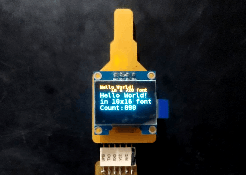
Here is the results after I tried out Vincent's code it was awesome he also converted the code to arduino environment means it still a C code but works in Arduino IDE.
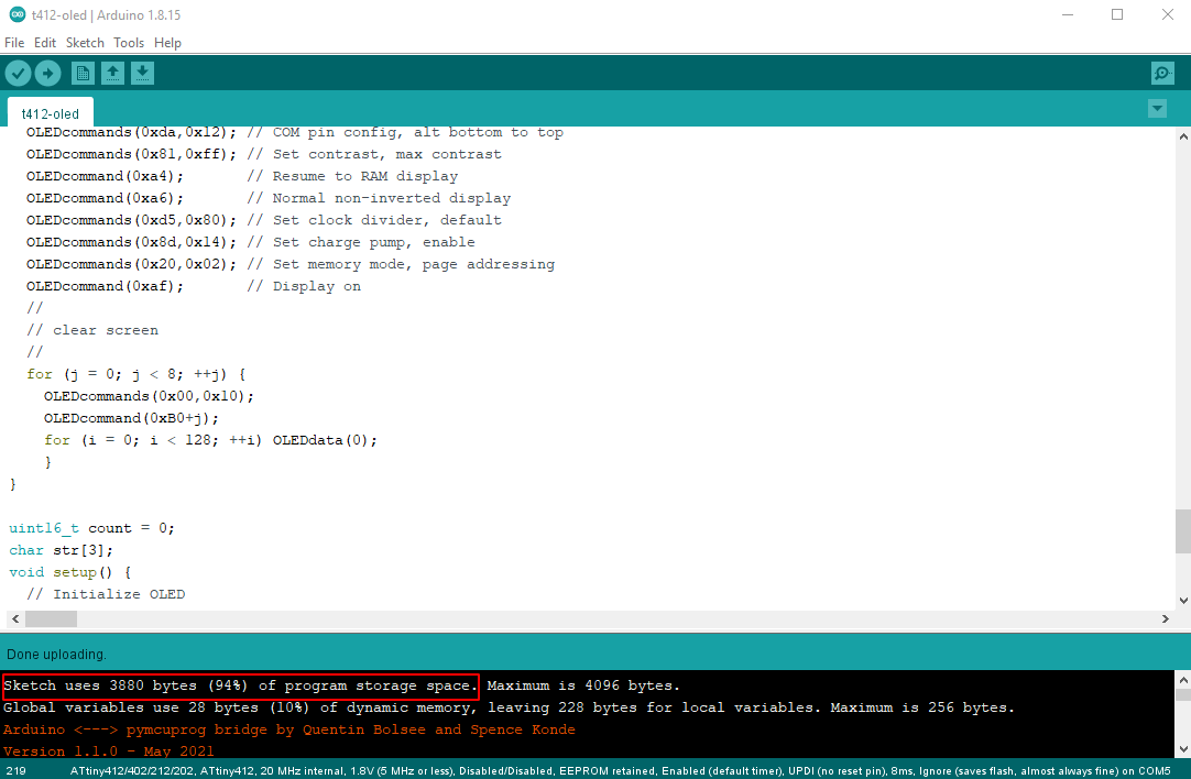
There is another problem caught in my attention which is the flash memory of the Attiny412 is 94% full because of the fonts in the program so I need to optimize and reduce in order to complete the tachometer program.
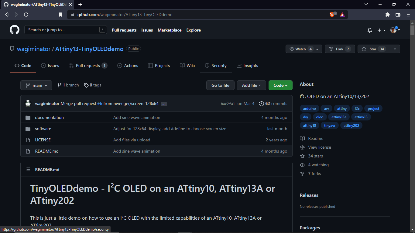
Again I used ll my effort and time through internet documentations and find out a github repo of a guy named Stefan wagiminator. He did an amazing job to write demo codes and projects for Attiny AVR series .So one of his project to interface the OLED display module in smallest microcontrollers like Attiny10,Attiny13 and Attiny202. check his ATtiny13-TinyOLEDdemo github repo here.
Group Assignment
week 12 Group assignment is to measure the power consumption of an output device
We all did not got chance to finish the project in the week so we done after our project presentation. For this week we wanted to know how much a servo takes the power while it's working. and planned to try out the stepper motor.The simple basic power calculation equation is given below
- Power (W) = Voltage(V) x Current (I)
Here we already aware of the Voltage that we are given to the component or circuit . There are many ways to measure current and calculate the Power consumption of an electronic device. We already met some of the electronic measurement equipments during the Electronics design week .That's made the jo easy.
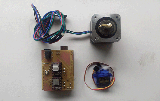
We are decided measure the power consumption of a servo motor and a Nema17 stepper motor .And also we are gonna use the 2 Axis CNC Shield with arduino UNO setup for making the Servo and stepper working .because both need control signals in order to perform.
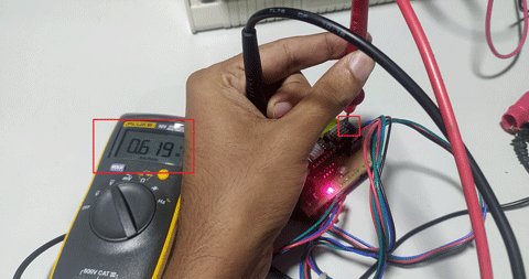
Before we connect any output device to the hardware we measured the power of the arduino UNO and shield setup.
- Voltage = 12 V
- Current = 0.06930 A
- Power = 12x0.0693
- = 0.8316 Watts
Power Consumption of a Servo Motor
We will be using a standard TowerPro SG90 Mini Servo with 180 degree rotation which works in the range of 3.0 ~ 7.2 VDC. And will be uploading the servo sweep example from arduino IDE to the Arduino Uno board.
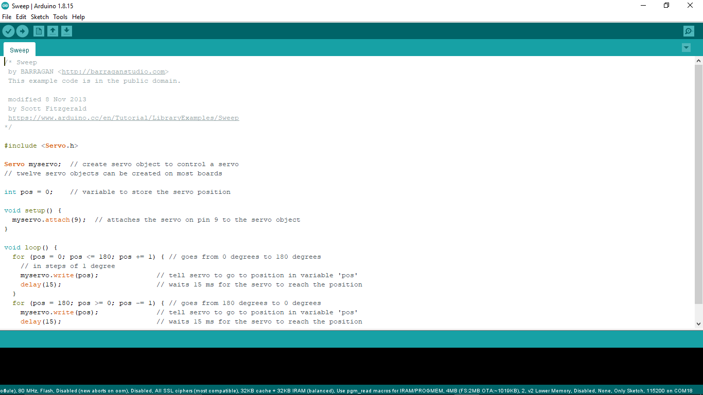
The code will works as sweeping motion that the angle of the servo will change from 0 to 180 degree and vice versa with a uniform time interval
SERVO SWEEP CODE :-
                    /* Sweep
                    by BARRAGAN
                    This example code is in the public domain.

                    modified 8 Nov 2013
                    by Scott Fitzgerald
                    https://www.arduino.cc/en/Tutorial/LibraryExamples/Sweep
                   */

                   #include < Servo.h>

                   Servo myservo;  // create servo object to control a servo
                   // twelve servo objects can be created on most boards

                   int pos = 0;    // variable to store the servo position

                   void setup() {
                     myservo.attach(9);  // attaches the servo on pin 9 to the servo object
                   }

                   void loop() {
                     for (pos = 0; pos <= 180; pos += 1) { // goes from 0 degrees to 180 degrees
                       // in steps of 1 degree
                       myservo.write(pos);              // tell servo to go to position in variable 'pos'
                       delay(15);                       // waits 15 ms for the servo to reach the position
                     }
                     for (pos = 180; pos >= 0; pos -= 1) { // goes from 180 degrees to 0 degrees
                       myservo.write(pos);              // tell servo to go to position in variable 'pos'
                       delay(15);                       // waits 15 ms for the servo to reach the position
                     }
                   }
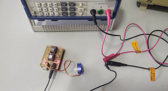
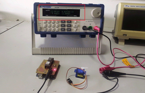
Here is our test setup After uploading the servo sweep program we attached the servo and hooked the shield to the power supply
You can see the test video above that the servo sweeps fom 0 to 180 degree and vice versa and we also observed the current consumption from the Power supply live reading
- Given Voltage = 12V
- Observed Current maximum = 0.1A
- the Power = 12x 0.1 = 1.5 Watts
- So the power of the servo alone = 1.5-0.8316
- =0.6684 Watts
Then we also tried giving a load push by our hand fingers pushing against the sweeping direction That takes more current for running the servo in position
- Given Voltage = 12V
- Observed Current maximum = 0.5A
- the Power = 12x 0.5 = 6 Watts
- So the power of the servo alone = 6-0.8316
- =5.1684 Watts
Power Consumption of a Stepper Motor
Now let's try a stepper motor in action , we are using NEMA 17 Stepper motor from our Inventory @ 12 volts in combination with the DRV 8825 Stepper drivers
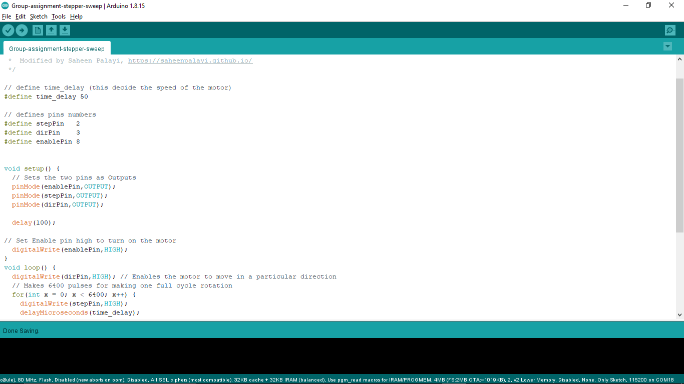
The code actually borrowed from HowToMechatronics.com stepper motor tutorials and made some changes of owr own for the hardware setup
STPPER SWEEP CODE :-
                    /*     Simple Stepper Motor Control Exaple Code
                    *
                    *  by Dejan Nedelkovski, www.HowToMechatronics.com
                    *  Modified by Saheen Palayi, https://saheenpalayi.github.io/
                    */

                    // define time_delay (this decide the speed of the motor)
                    #define time_delay 50

                    // defines pins numbers
                    #define stepPin   2
                    #define dirPin    3
                    #define enablePin 8


                    void setup() {
                    // Sets the two pins as Outputs
                    pinMode(enablePin,OUTPUT);
                    pinMode(stepPin,OUTPUT);
                    pinMode(dirPin,OUTPUT);

                    delay(100);

                    // Set Enable pin high to turn on the motor
                    digitalWrite(enablePin,HIGH);
                    }
                    void loop() {
                    digitalWrite(dirPin,HIGH); // Enables the motor to move in a particular direction
                    // Makes 6400 pulses for making one full cycle rotation
                    for(int x = 0; x < 6400; x++) {
                    digitalWrite(stepPin,HIGH);
                    delayMicroseconds(time_delay);
                    digitalWrite(stepPin,LOW);
                    delayMicroseconds(time_delay);
                    }
                    delay(1000); // One second delay

                    digitalWrite(dirPin,LOW); //Changes the rotations direction
                    // Makes 6400 pulses for making one full cycle rotation
                    for(int x = 0; x < 6400; x++) {
                    digitalWrite(stepPin,HIGH);
                    delayMicroseconds(time_delay);
                    digitalWrite(stepPin,LOW);
                    delayMicroseconds(time_delay);
                    }
                    delay(1000);
                    }
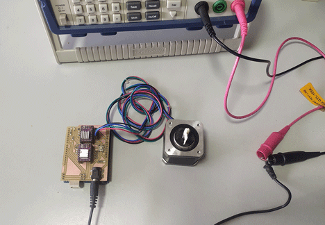
Here is our Stepper sweep test setup just like the servo. But we are using the DRV8825 module as the stepper driver for the NEMA17 stepper motor.
In the test 1 the motor moves back in forth 1 revolution we taped the motor shaft for capturing the motor movement in camera. At the is condition no load on the motor presents and the current was very less.
- Given Voltage = 12V
- Observed Current maximum = 0.35A
- the Power = 12x 0.35 = 4.2 Watts
- So the power of the Stepper alone at no load condition = 4.2-0.8316
- =3.3684 Watts
We decide to give some load on the motor.so, for that we attached a GT2 pulley for trying to hold the motor while running.
Here the above video shows the test 2 of the stepper motor that we are trying to hold the motor while rotating which act as a load on the motor and the current dose increased littil bit.
- Given Voltage = 12V
- Observed Current maximum = 0.48A
- the Power = 12x 0.48 = 5.76 Watts
- So the power of the Stepper alone at no load condition = 5.76-0.8316
- =4.9284 Watts
And still it's not reach the specified power consuption by the manufacturer . we thought the load wasn't enough and we need to increase.
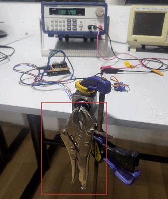
so we built a test bench set up using a wrench and holded the motor on the table's end using a clamp.
In the video of test 3 we can see the motor skipping the steps to lift the wrench which is attached to the stepper motor's shaft.Which means it doesn't have the poer to list the wrench.
Then we realize this happening becouse the stepper driver not allowing to rise the current for the stepper motor over a certine level so we adjusted the Vref for the DRV8825 by turning the pot on the stepper driver.
Then we repated the test again this time the minmum power increased to 0.55A first we did the no load test also turned on the microsteppring for the motor driver.
- Given Voltage = 12V
- Observed Current maximum = 0.557A
- the Power = 12x 0.557 = 6.684 Watts
- So the power of the Stepper alone at no load condition = 6.684-0.8316
- =5.8524 Watts
Then we repated the wrench load test again as test 5 this time the current rised .
- Given Voltage = 12V
- Observed Current maximum = 0.61A
- the Power = 12x 0.61 = 7.32 Watts
- So the power of the Stepper alone at no load condition = 7.32-0.8316
- =6.4884 Watts
From all of these 5 tests with the stepper motor we undersatand the we can mess with the power consuption by adjusting the stepper driver's Vref voltage.
References
- Fab Academy Output Devices classes
- www.analog.com | I2C Tutorial
- howtomechatronics.com | I2C Arduino Tutorial
- u8g2 github Repository
- Vincent-Zhou's Fab documentation
- Stefan Wagner's ATtiny13-TinyOLEDdemo github Repository
Downloads
- Attiny Tachometer PCB Design files