Week 15 SYSTEM INTEGRATION
Objectives
Design and document the system integration for your final project
- This week the main objective was to thoughrly think about how we can package the hardware components of our final project.
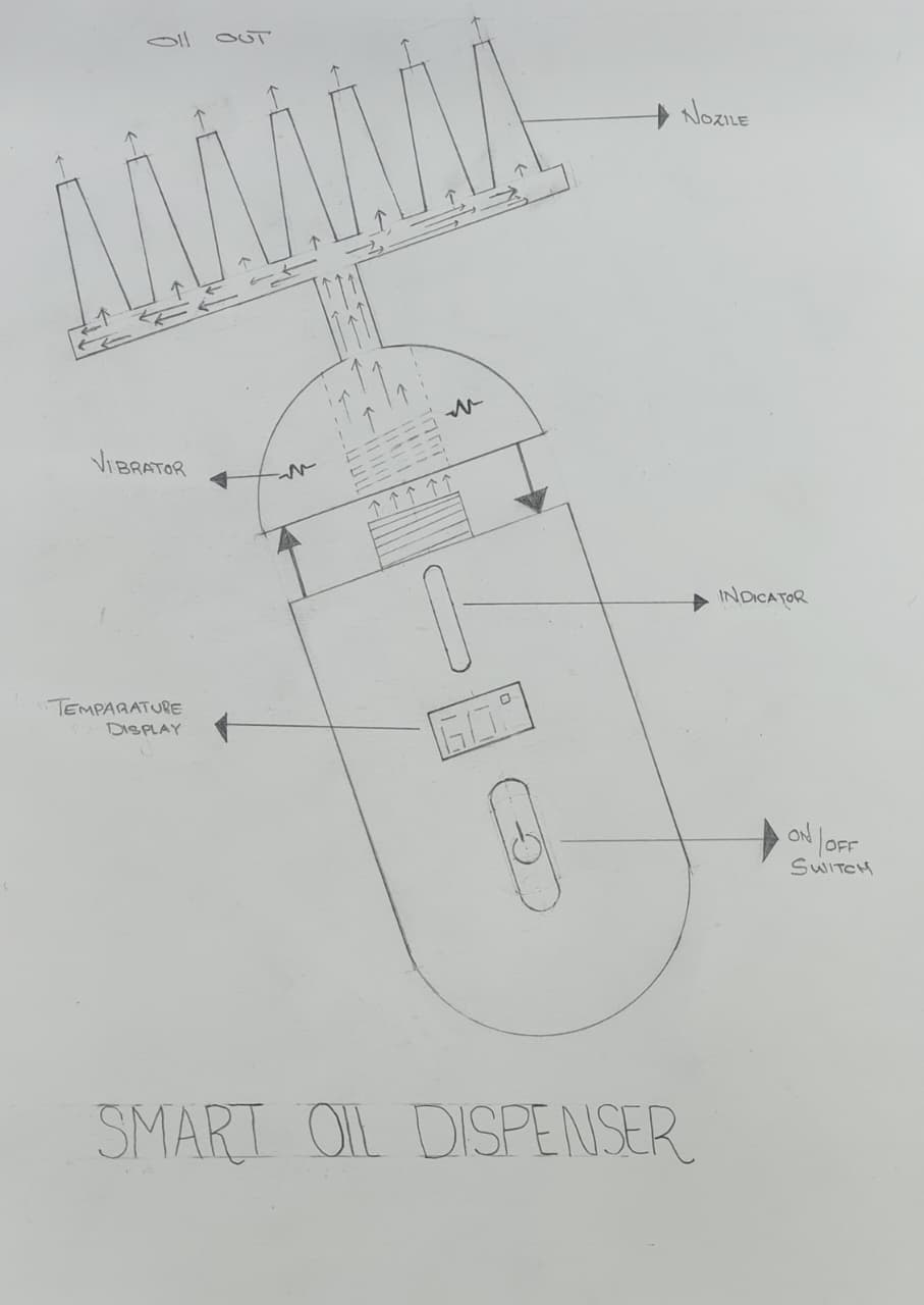
- Aura Smart Hair Oil Dispenser is a compact personal care device that combines controlled oil heating, precise dispensing, and scalp massage to improve hair nourishment. It uses a thermally efficient aluminum chamber (up to 60 °C), a precision nozzle, and a vibration motor to enhance oil absorption and blood circulation. The device features an ergonomic design with wireless charging for safe and convenient use.
Product Image Prompt
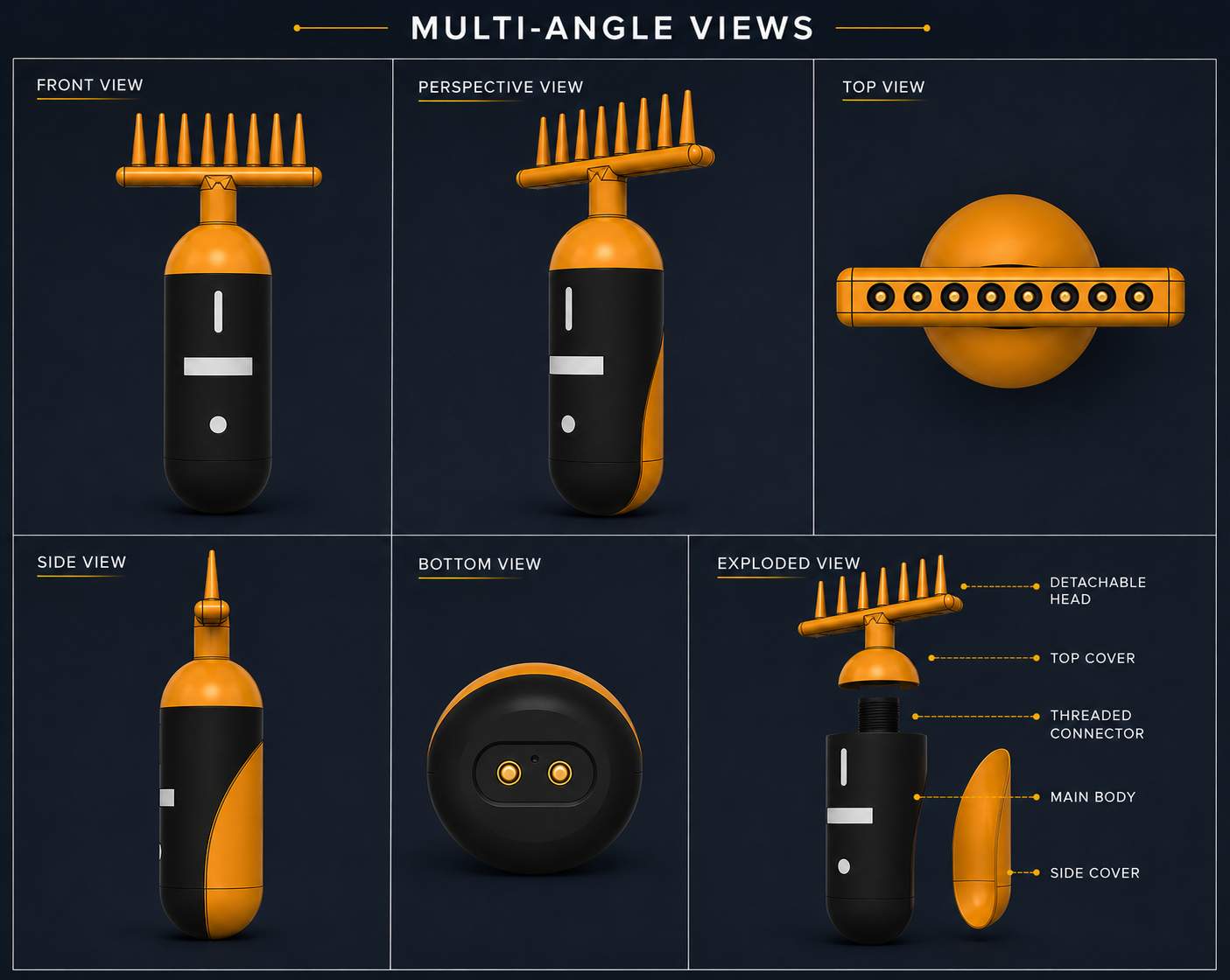
Make a cool product image showing a smart hair oil device in many angles like front, side, top, and bottom. Keep the same dark blue background and do not change it. Use black and orange colors for the device. Show one exploded view where parts are separated and labeled. Add soft light and shadow to make it look real and professional. Keep the layout neat like a grid with small titles for each view.
AI Tool Used: ChatGPT
Color Palette Prompt
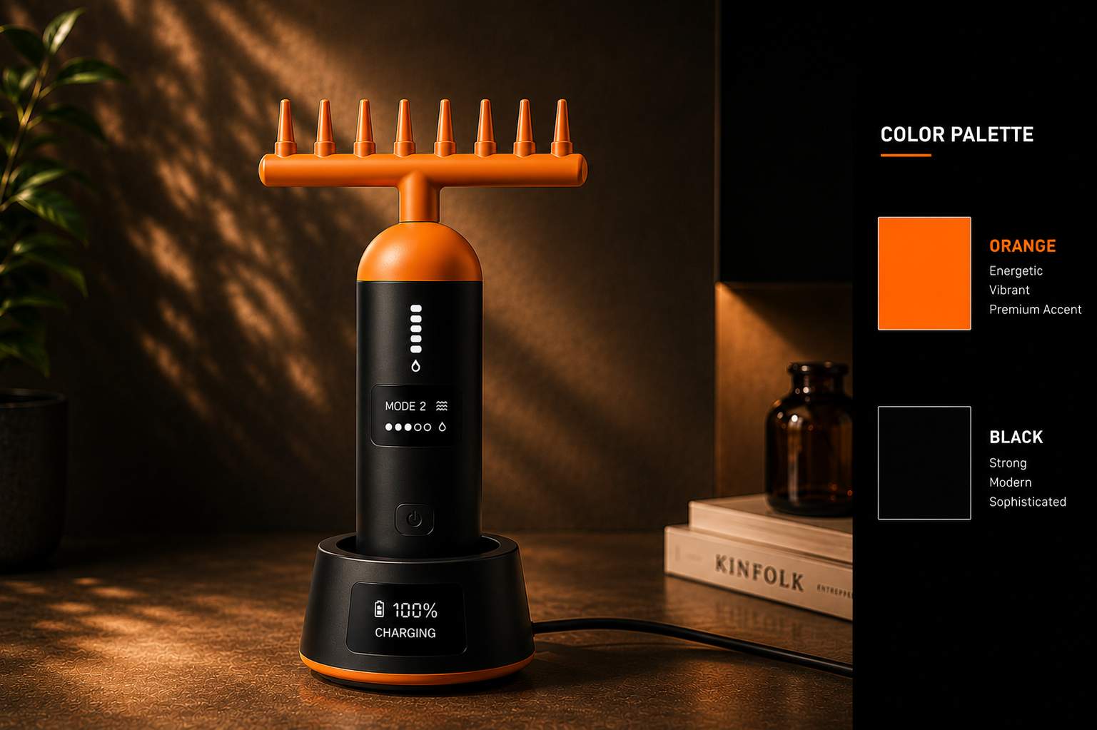
Add a small color palette in the corner of the image. Use only orange and black colors. Show two simple color boxes with labels orange and black. Keep it clean and minimal. Do not change the main product or background. Place it neatly in the corner like a professional design.
AI Tool Used: ChatGPT

Iteration 1
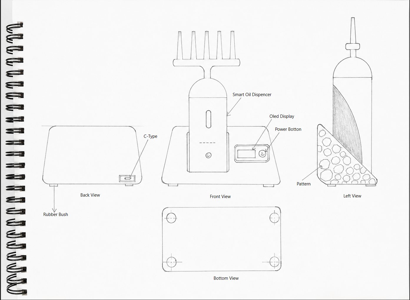
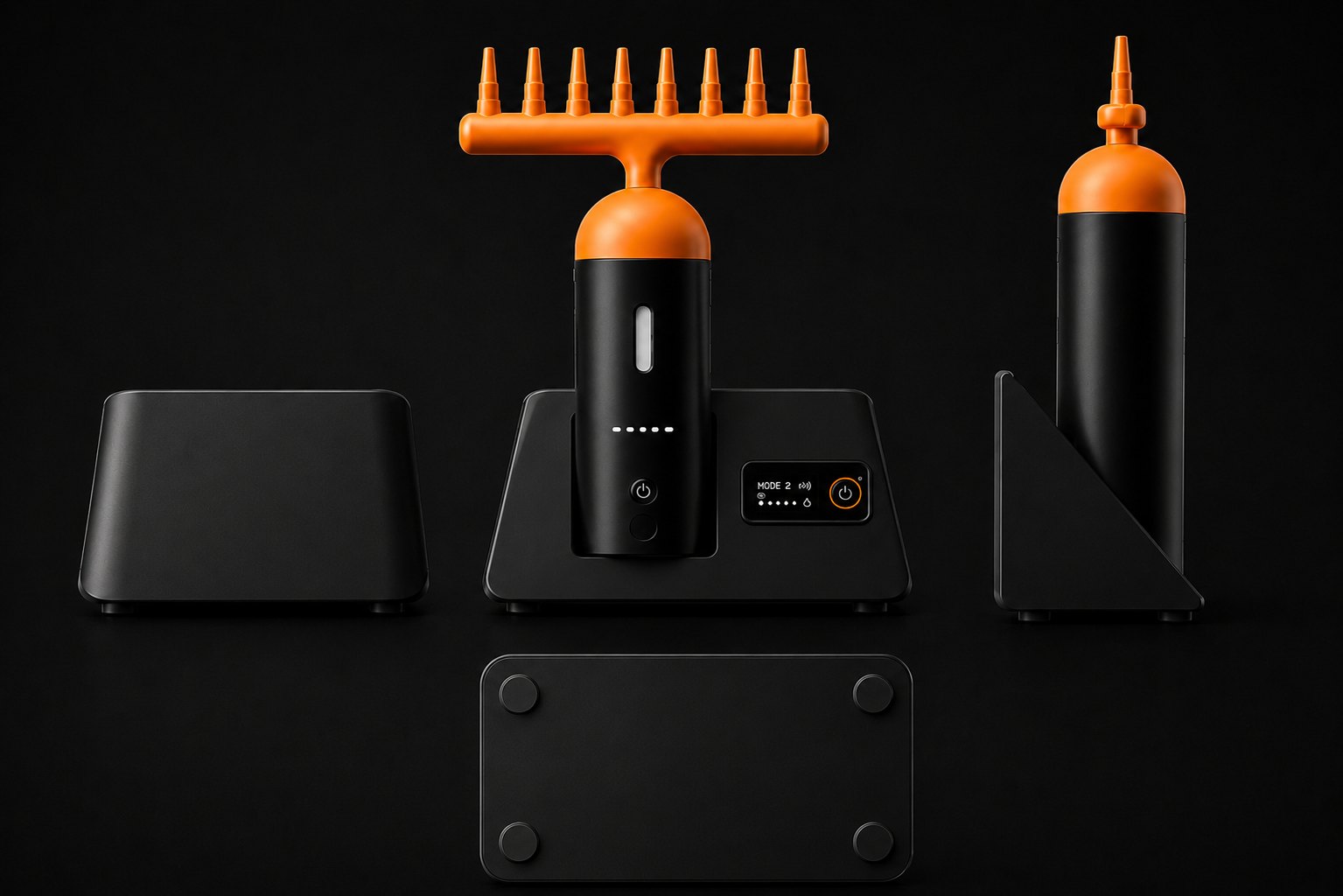
Image Prompt
Design a compact smart oil dispenser with a docking station. The device has a vertical cylindrical body with a small display and a power button in front. The top has multiple nozzle outlets for dispensing oil. The docking station is simple and stable with a slight angled support. Include a small OLED display and control button on the base. Add a USB Type-C charging port at the back and rubber supports at the bottom. Keep the design minimal, easy to carry, and modern using black and orange colors.
AI Tool Used: ChatGPT
Design Note
Userflow Diagram
The first step was to define and document the complete user flow in a notebook, outlining how users would interact with the product from charging and heating to oil application and vibration control.
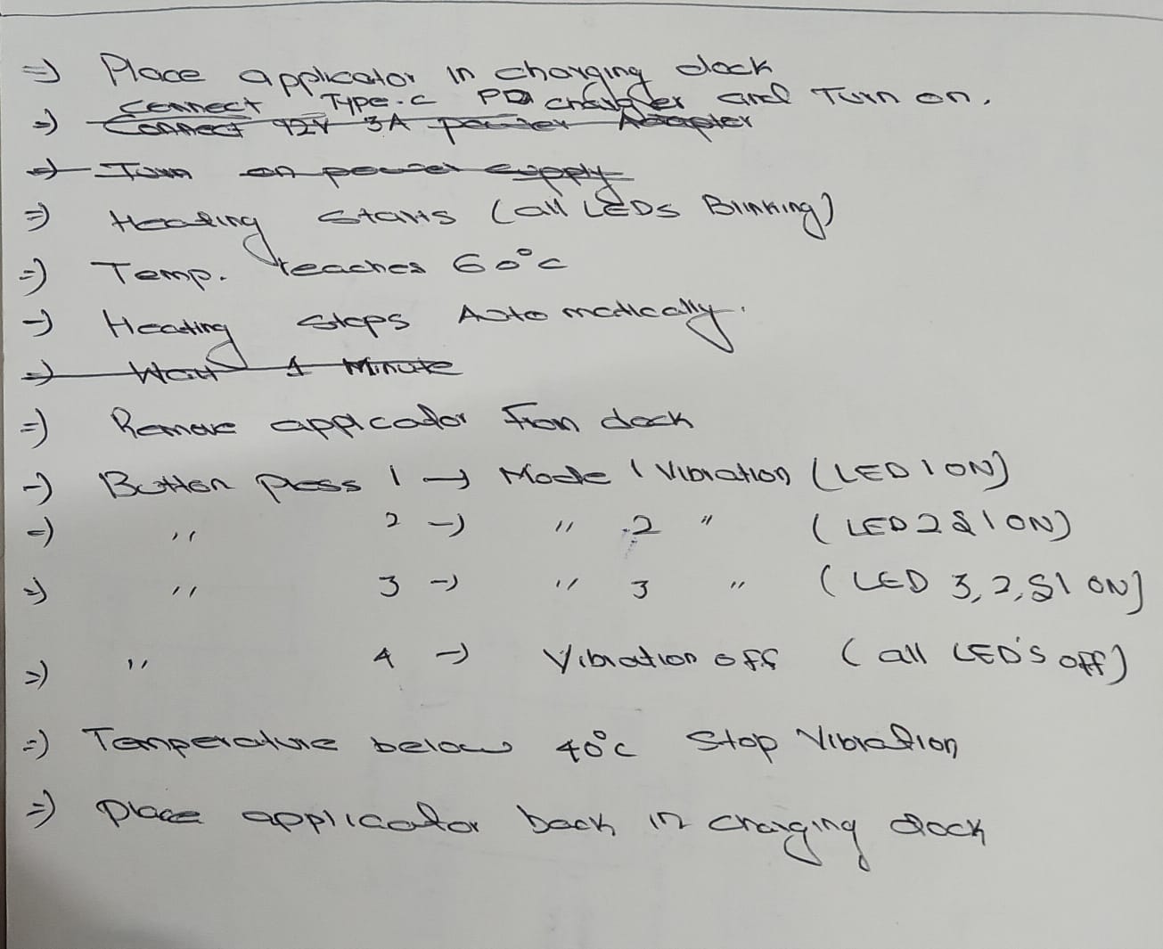
After that I asked to chatgpt to make a userflow diagram
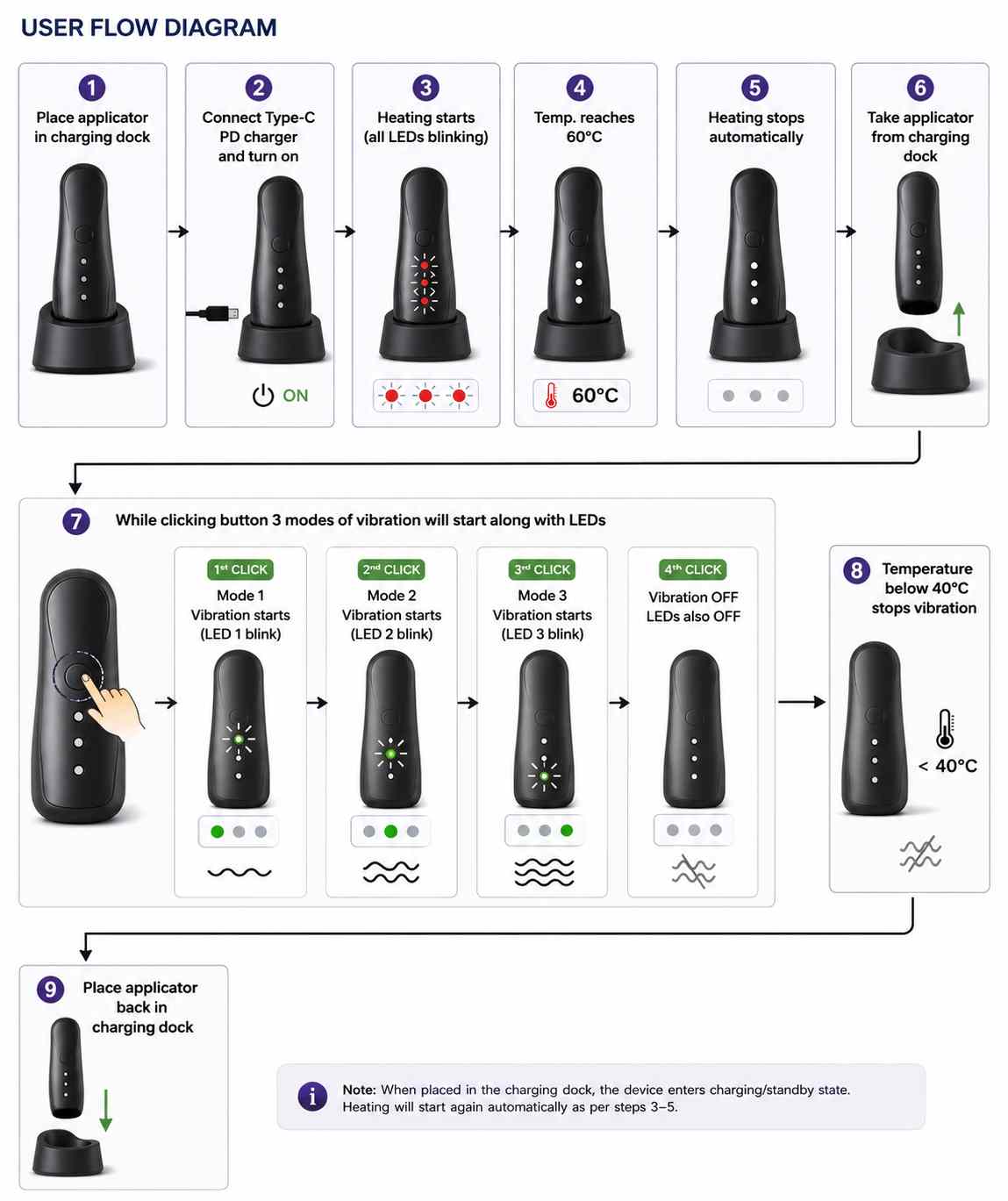
AI Image Prompt
Prompt: " make a user flow diagram. 1.place applicator in charging dock 2.connect type-c pd charger and turn on 3.heating starts (all leds blinking) 4.temp.reaches 60°c 5.heating stopes automatically 6.take applicator from charging dock 7.while clicking button 3 modes of vibration whill start along with leds 1 1st click mode 1 vibration will start (led 1 blink) 2 2nd click mode 2 vibration will start (led 2 blink) 3 3rd click mode 3 vibration will start (led 3 blink) 4 4rth click vibration will off and leds also off 8.temparature bellow 40°c stops vibration 9.Place applicator back in charging dock.
AI Tool Used: ChatGPT
Cardboard Mockup
I made a cardboard mockup to try this out and also check how the dimensons turned out
Laser Cutting Process
I used a 3mm Cardbord for cutiing
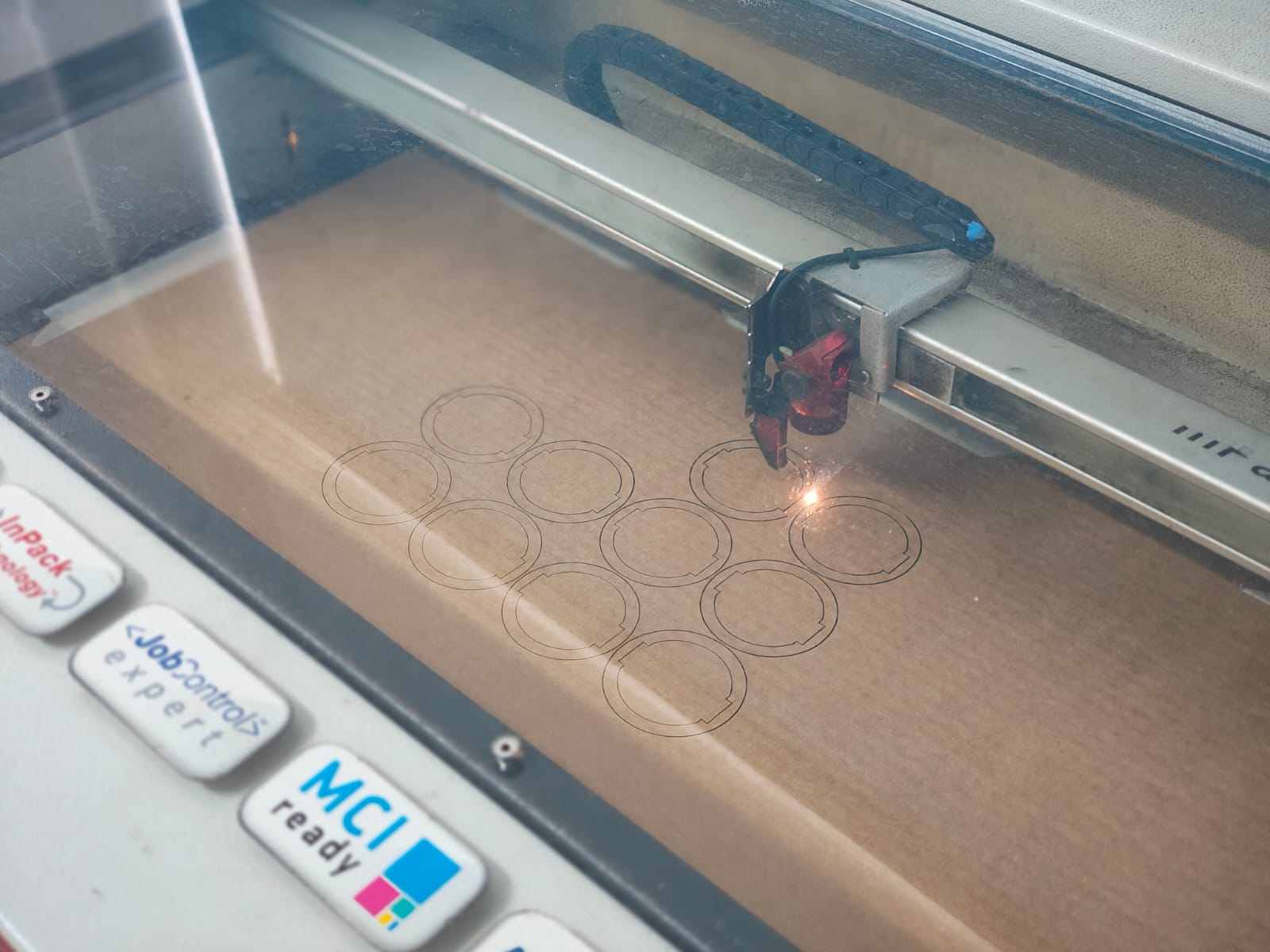
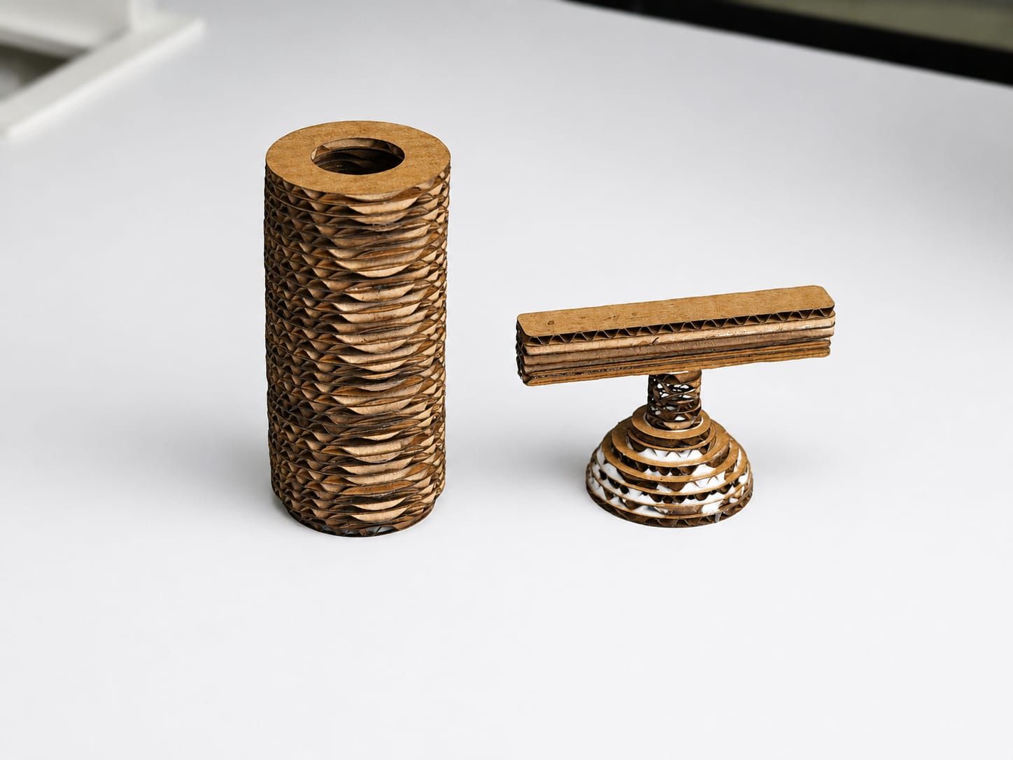
This is final view of laser cutting here there is all shapes iwant for making mockup
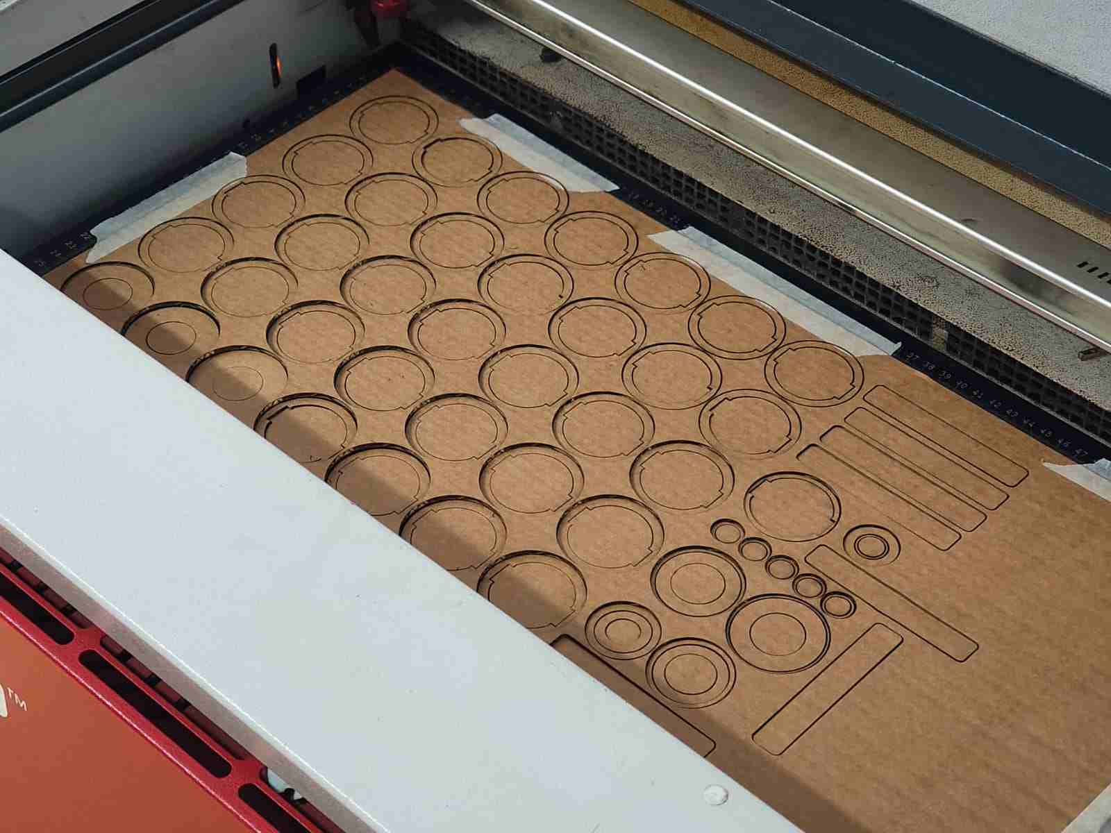
After laser cutting, all the inner shapes were carefully removed from the parts. The individual layers were then aligned and assembled according to the design. I used Feviquick adhesive to bond the layers together, creating a strong and rigid stacked structure. The assembled parts were held in position until the adhesive cured completely, ensuring proper alignment and structural stability.
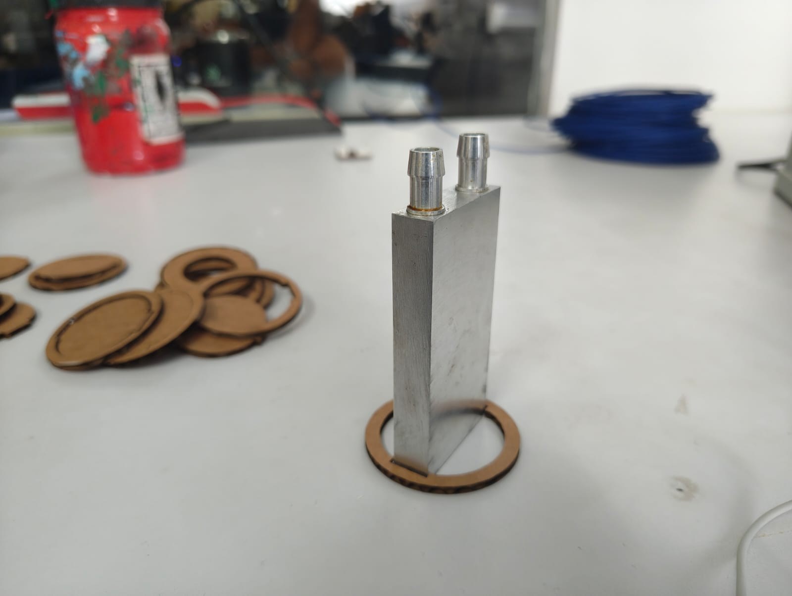
When the cardboard assembly was approximately halfway completed, I inserted the aluminum cooling block into the structure. Before continuing the assembly, I carefully checked the fit and tolerance to ensure that the aluminum oil block could be placed securely without excessive force or looseness. After confirming proper alignment and clearance, the remaining layers were glued and assembled, permanently fixing the cooling block within the structure.
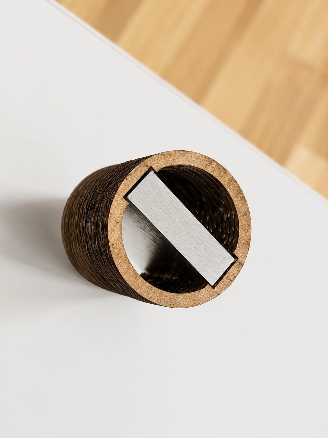
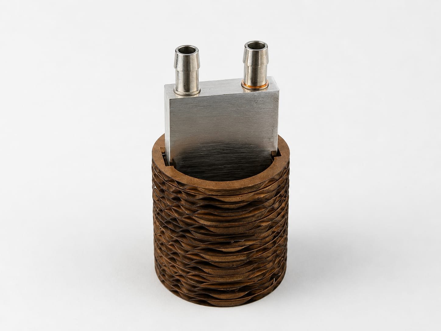
After completing the assembly process, the final cardboard mockup was successfully fabricated by stacking and bonding the laser-cut layers using Feviquick adhesive. The assembled prototype accurately represents the intended form and dimensions of the final product. This mockup was used to verify the overall shape, structural integrity, component placement, and fit of the aluminum cooling block before proceeding to the next stage of development. The successful assembly confirmed that the design, tolerances, and manufacturing approach were suitable for the final implementation.
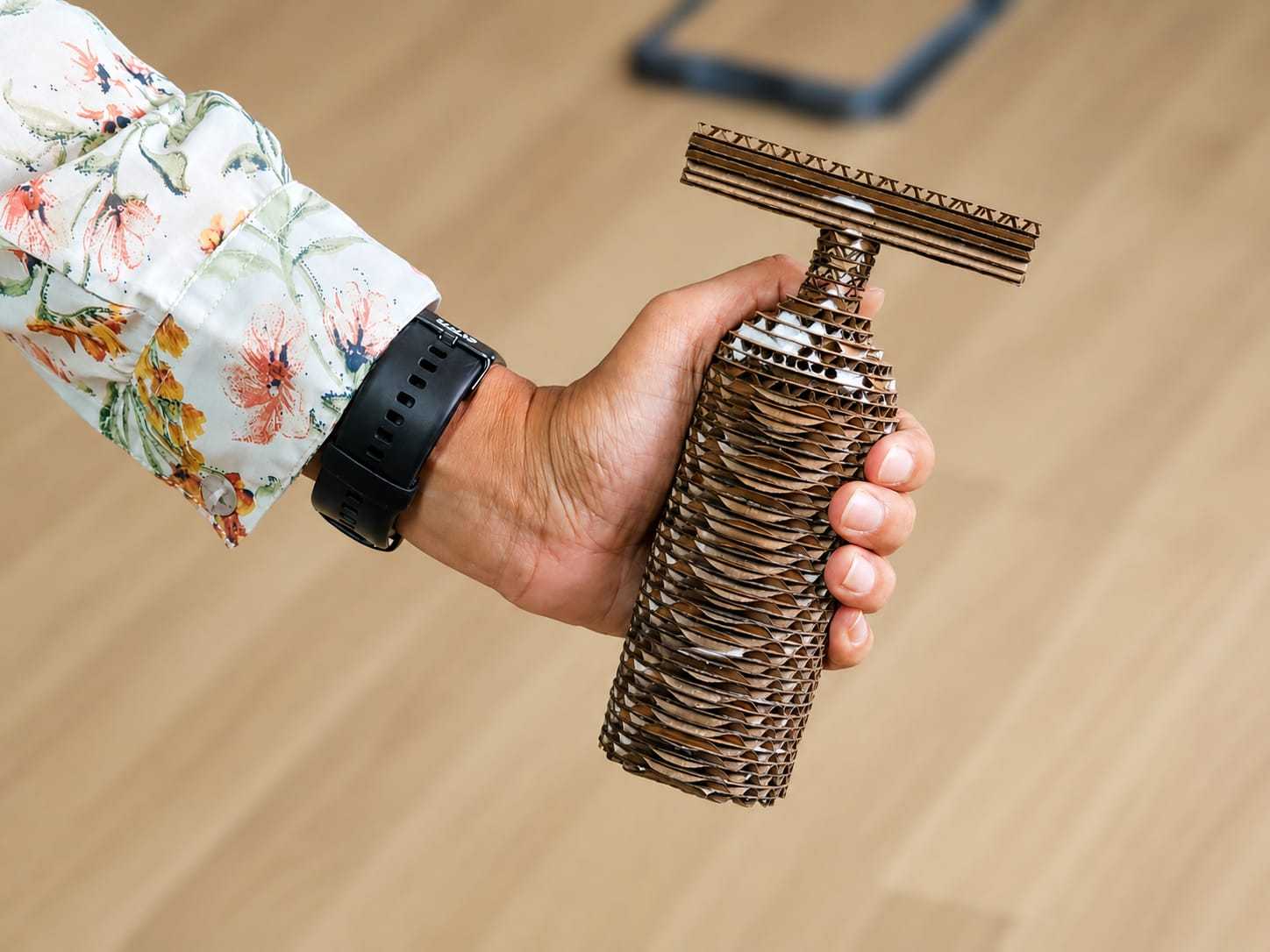
After completing the assembly, I performed a grip and ergonomics test to evaluate how the mockup felt in the user's hand. The prototype was held in a natural operating position to assess comfort, balance, and ease of handling. This test helped verify that the dimensions and overall form factor were suitable for prolonged use. The results confirmed that the design provided a comfortable grip and could be easily operated with one hand.
PCB Testing
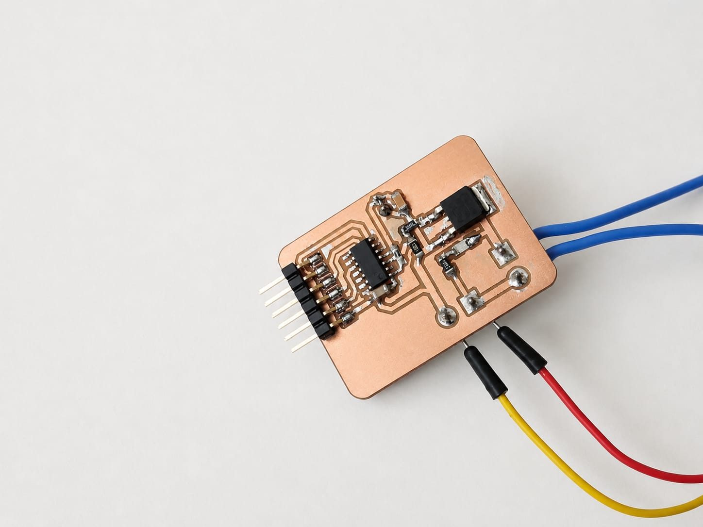
Pcb With Ptc heater and Thermister. For more detailes you can go and visit Week 10
Section Analysis
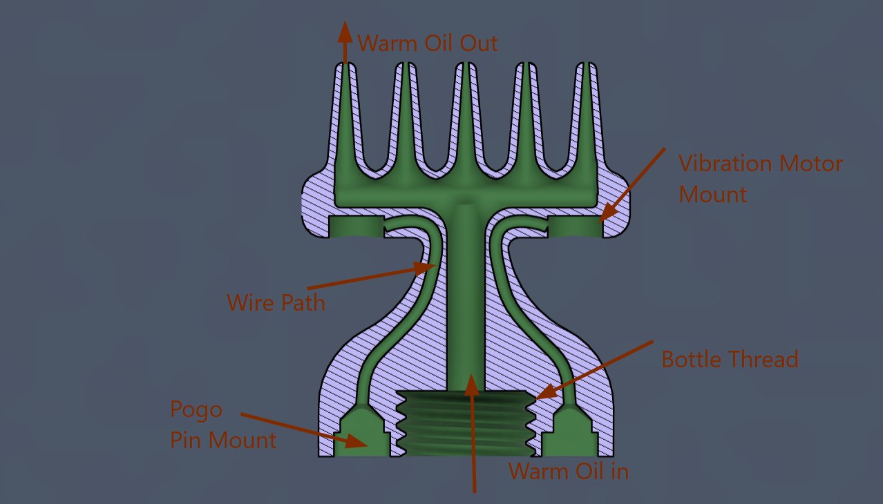
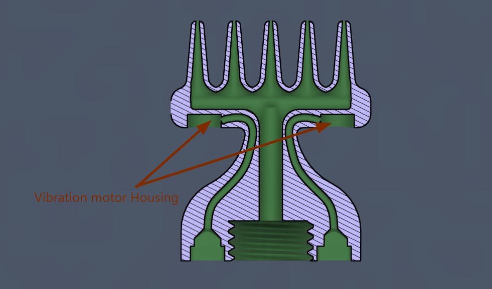
This sectional view illustrates the internal design of the oil applicator head. Warm oil enters through the threaded bottle connection at the bottom and flows upward through the central channel before being distributed to the applicator tips. The design includes dedicated wire paths for routing electrical connections from the main body to the vibration motors mounted on both sides of the applicator head. Pogo pin mounts are integrated into the structure to provide detachable electrical connections between the applicator and the main device. This arrangement enables simultaneous oil dispensing, vibration massage, and easy assembly while maintaining a compact and ergonomic design.
Exploded View

- Outer Body, Oil Applicator, Top Cover, and Bottom Cover – Manufactured using 3D printing (PLA material).
- PCB – Fabricated by PCB milling on FR1 board.
- Heating Block – Produced through silicone molding and casting using an aluminum-filled casting material.
- Battery, Heater, and Electronic Components – Purchased standard components and assembled into the final product.
Wiring
System integration diagram showing the interconnection of the custom PCB, 100K NTC thermistor, 12V PTC heater, vibration motors, pogo pin connectors, TP4056 charging module, and rechargeable battery. This diagram illustrates how the electronic, thermal, power, and vibration subsystems are integrated to form the complete Smart Hair Oil Dispenser.
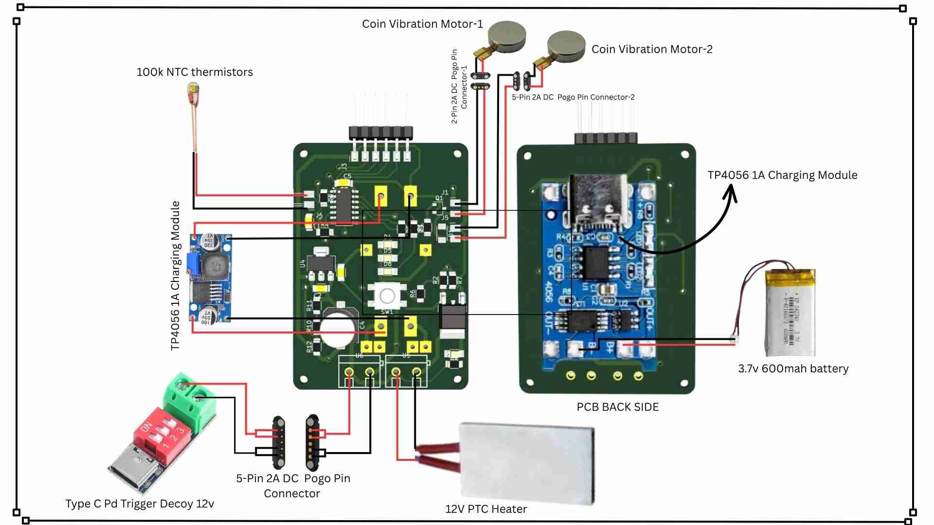
- Canva – Used to create wireing
Connectors and Wiring
Wire
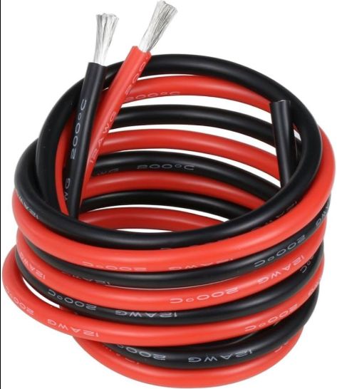
Silicone wire was used for the electrical connections inside the oil applicator because it is highly flexible, making it easy to route through the internal wire channels. In addition, silicone insulation provides good heat resistance, allowing the wire to operate safely near the heated oil path and heating block without degrading or becoming brittle over time.
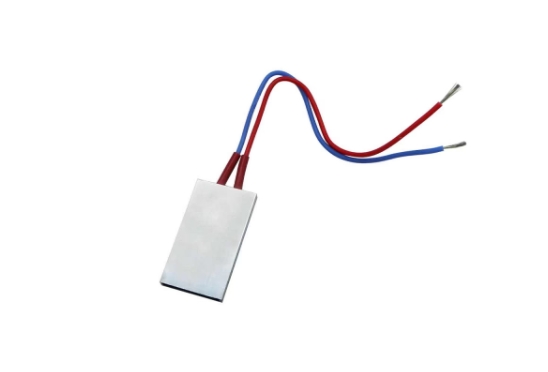
in this 1st image you can see ptc heater itself comes with silicone wire
Connectors
Applicator and comp
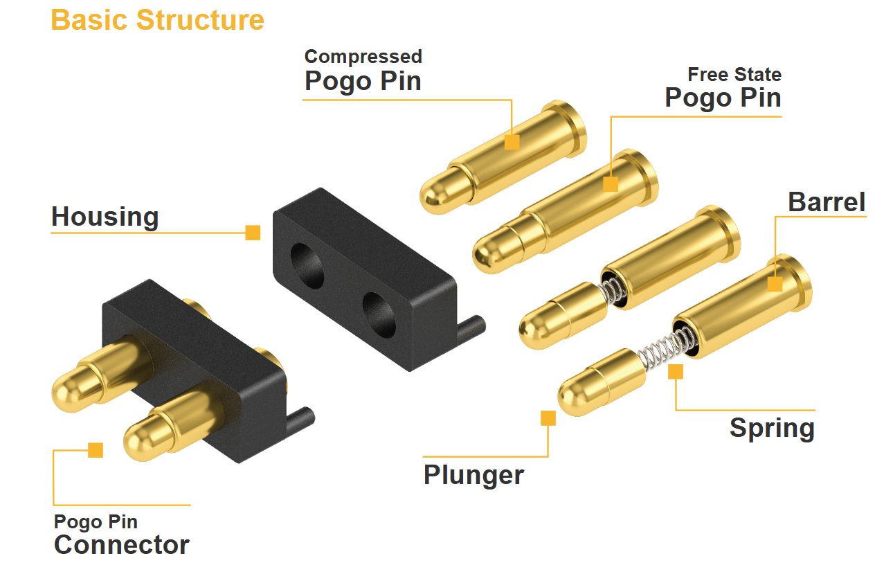
To power the vibration motors in the detachable oil applicator, I designed and fabricated custom pogo pin connections. These pogo pins provide a reliable electrical connection while allowing the applicator head to be easily removed and reattached without the need for exposed wires or connectors.
To provide a clearer understanding of the concept and user interaction, I have included an image from the final project presentation. This image helps visualize the overall workflow, design intent, and key features of the product, making the development process easier to understand.
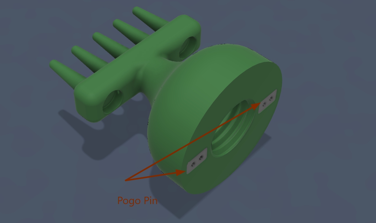
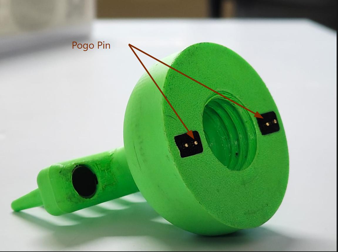
Comparison between the KiCad 3D PCB model and the final assembled prototype, showing the alignment of the pogo pins used to transfer power to the vibration motor through dedicated PCB contact pads. The image captured after the final project assembly provides a clearer understanding of how the mechanical and electrical components integrate in the completed design.
Connection between dock and applicator
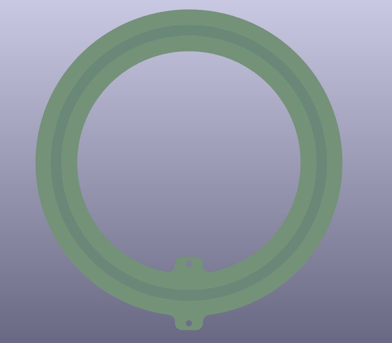
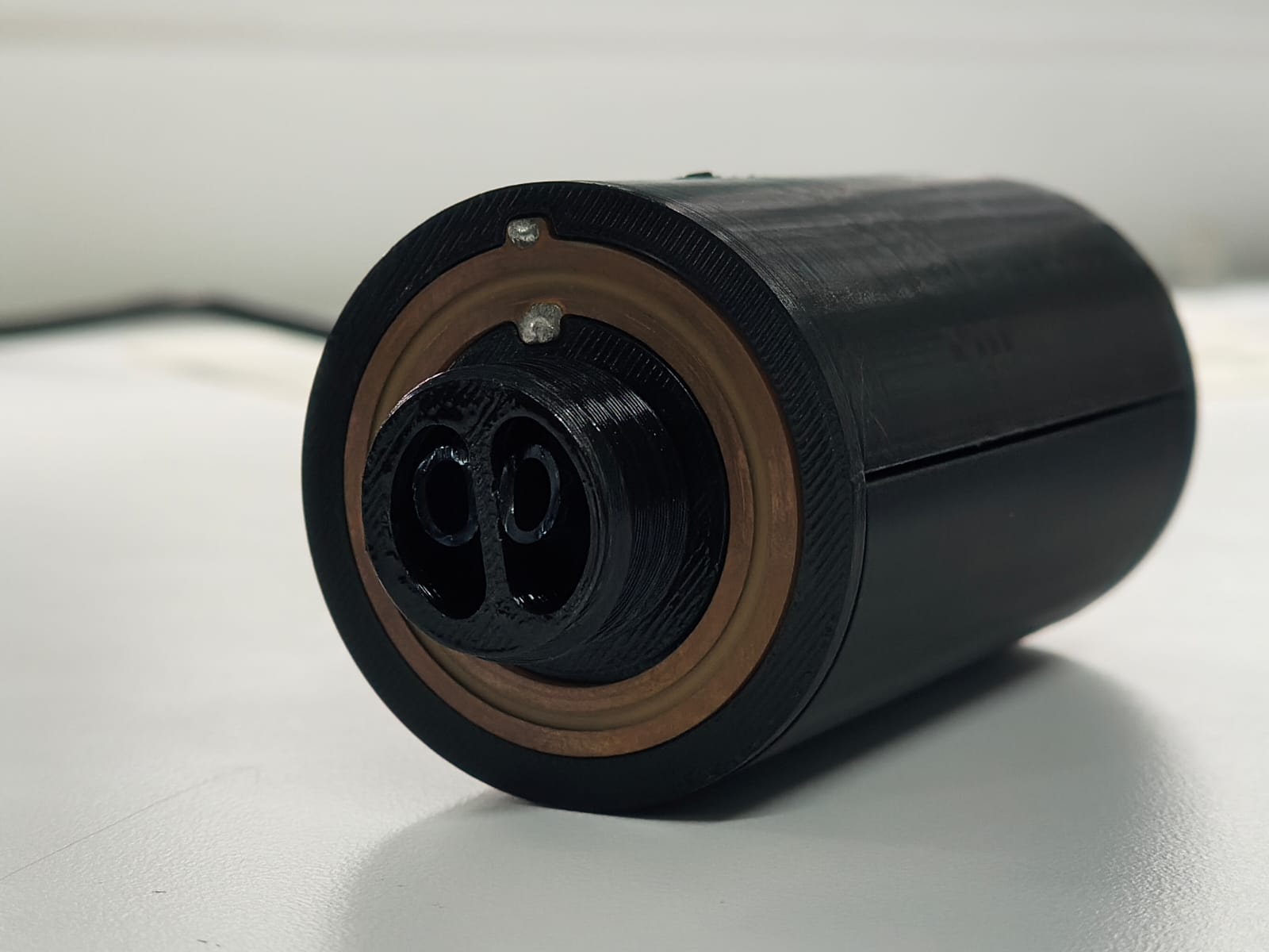
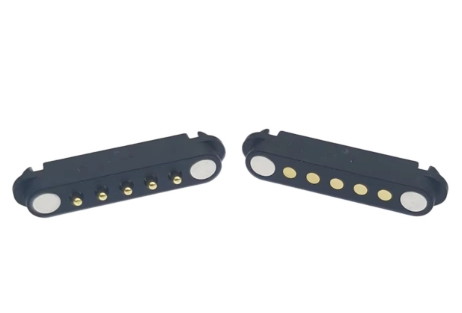
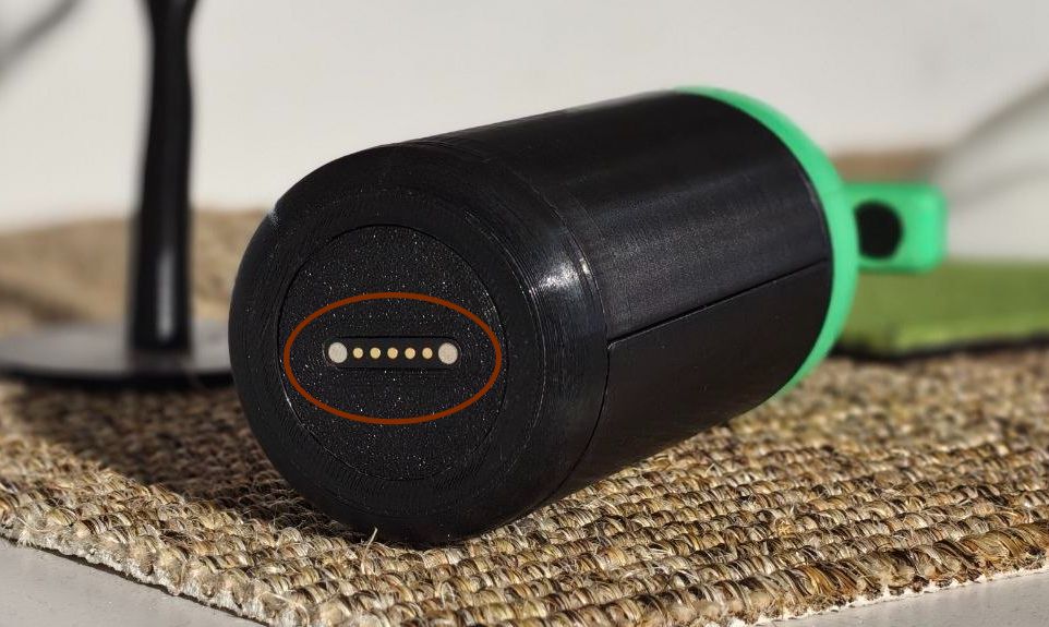
To transfer power between the charging dock and the applicator, I integrated a custom 5-pin pogo pin connector system. The pogo pins are designed to carry up to 12V at 2.5A, providing a reliable electrical connection while allowing the device to be easily docked and removed. This approach eliminates the need for exposed wires and improves the overall user experience and durability of the product.
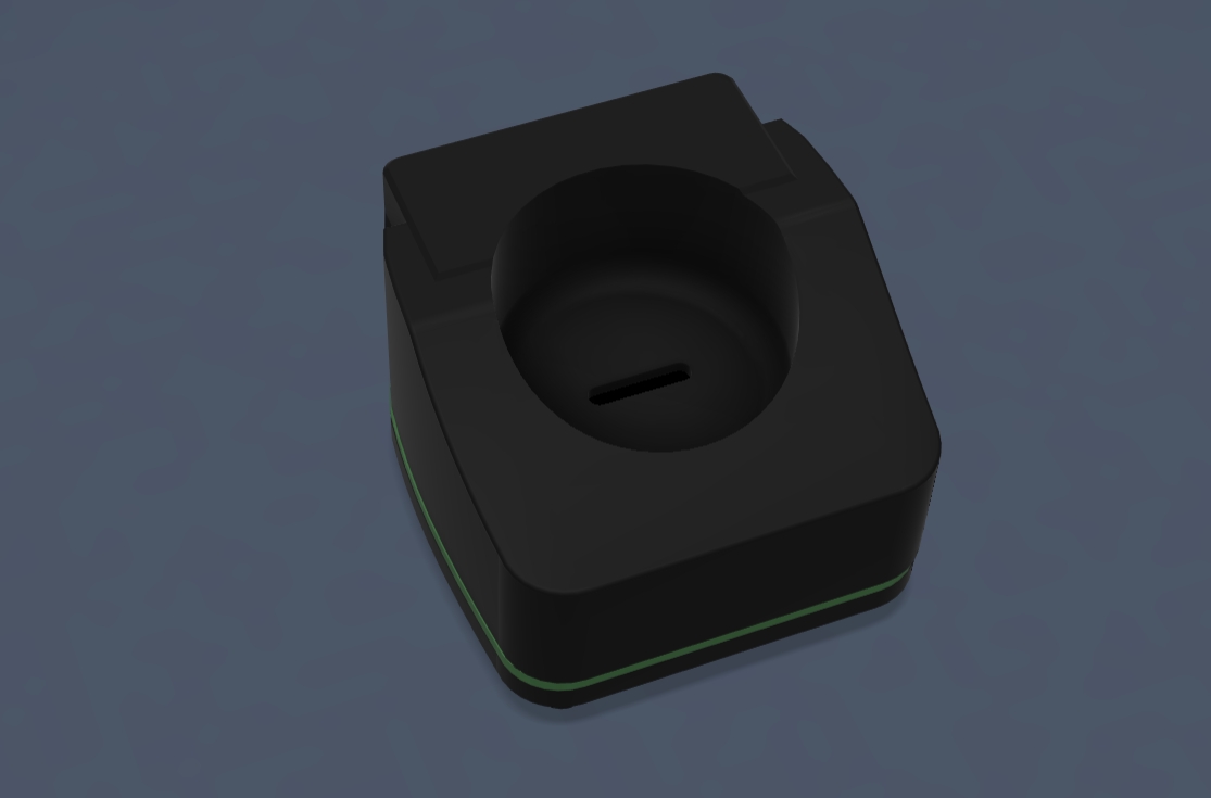
CAD visualization of the charging dock and applicator assembly. The applicator is designed to sit securely inside the charging dock, where the pogo pins establish electrical contact for battery charging and power transfer.
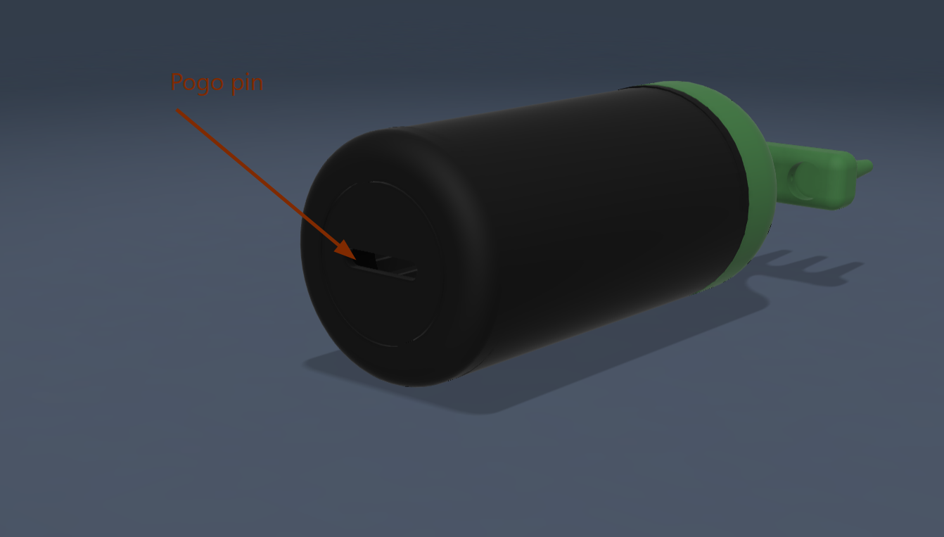
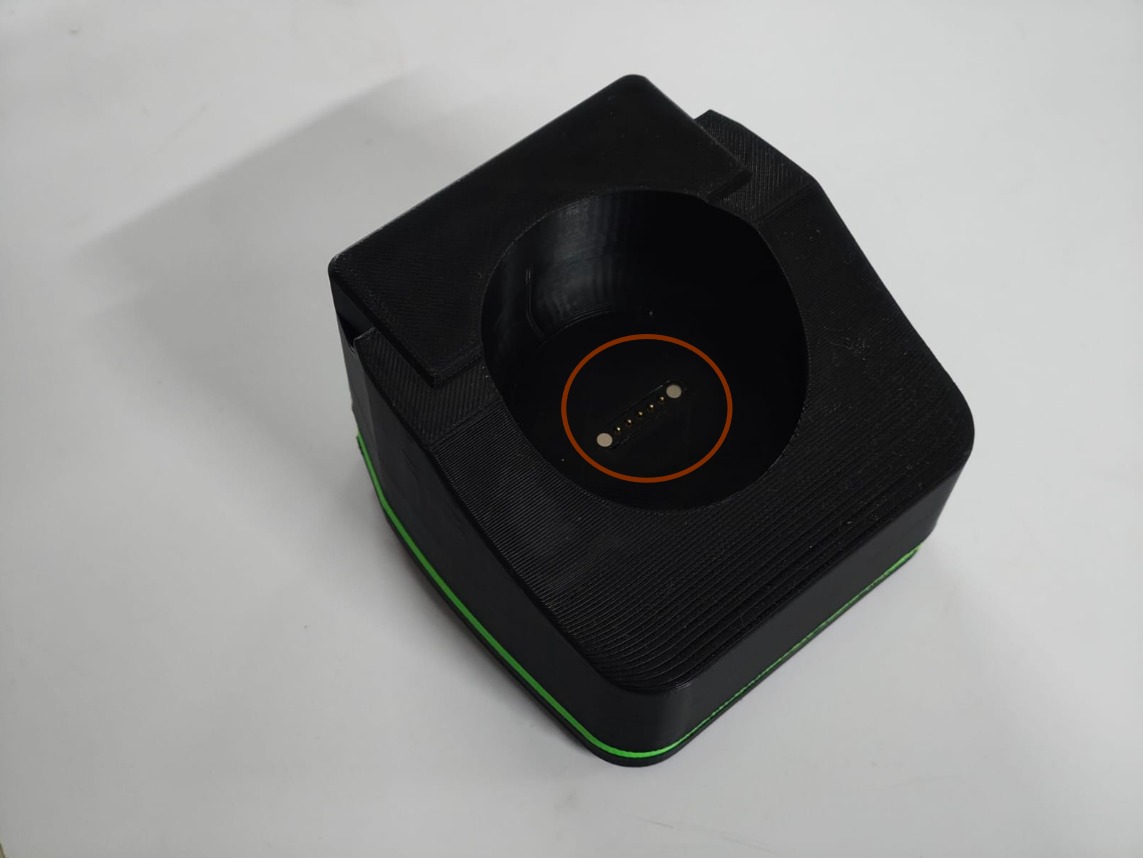
To provide a clearer understanding of the charging interface shown in the CAD model, I added photographs of the final assembled charging dock and applicator. The highlighted pogo pins and contact pads demonstrate how the electrical connection is established when the applicator is placed in the charging dock, validating the design shown in the CAD model.
Vibration Motor
To better visualize the internal design, I created a section view of the CAD model showing the vibration motor housing and PCB enclosure. This view helps illustrate how the components are securely mounted and integrated inside the applicator.
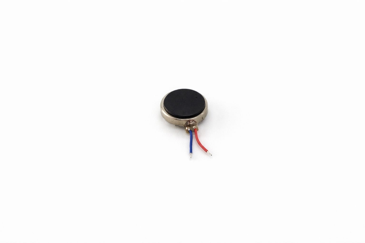
The same coin vibration motor I used in Week 10– Output Devices
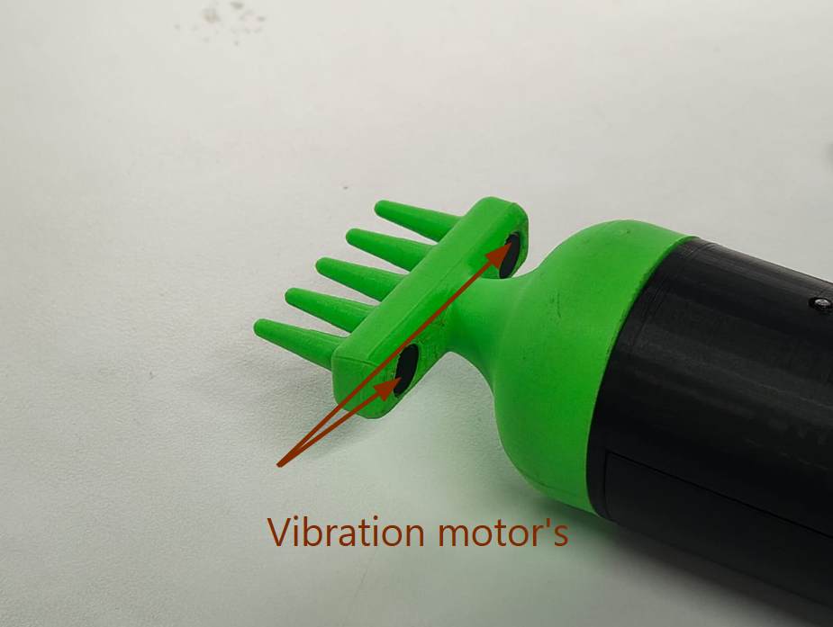
To provide a better understanding of the vibration mechanism, I added a photograph of the final assembled applicator. The highlighted openings show the location of the vibration motors positioned inside the massage head, which transfer vibrations directly to the scalp through the applicator tips.
Heating Block Fabrication Using Silicone Casting
The CAD model bellow illustrates the heating block assembly used for the silicone casting process. A 2 mm hole was drilled into the aluminum block to accommodate a 100k NTC thermistor. The thermistor was inserted into the hole using thermal paste to ensure accurate temperature sensing and efficient heat transfer.
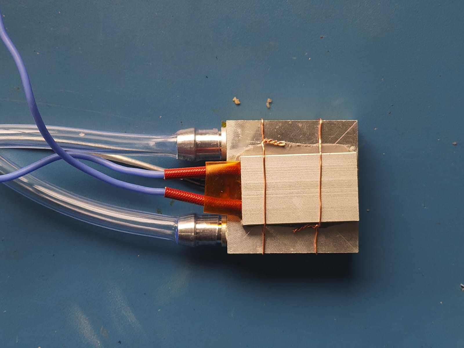
A PTC heater was then placed on top of the aluminum block. To maintain good thermal contact during casting, the heater was securely fixed using Kapton tape and copper wire. This assembly ensured that the heater and temperature sensor remained in their correct positions throughout the molding process.
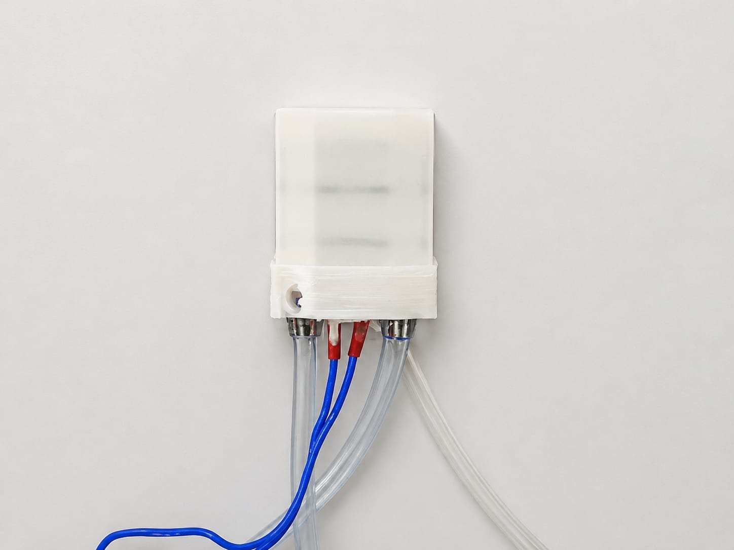
A 3D-printed enclosure was used as the mold for the silicone casting. Silicone was poured into the mold to encapsulate the aluminum block, PTC heater, and thermistor, creating a compact and insulated heating module. After the silicone had fully cured, the 3D-printed mold was carefully removed, leaving the completed silicone-cast heating assembly ready for integration into the final product.
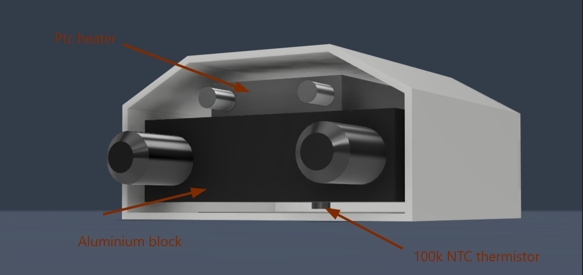
To provide a clearer understanding of the final heating module, I have included photographs taken after the fabrication process was completed. These images show the assembled aluminum heating block with the PTC heater, NTC thermistor, silicone encapsulation, and fluid connections. Comparing the fabricated module with the CAD model demonstrates how the design was successfully implemented in the final prototype.
BOM
| Sl | Component | Qty | Specification | Unit (₹) | Total (₹) | Vendor | Link |
|---|---|---|---|---|---|---|---|
| 1 | XIAO ESP32C6 | 1 | Controller | 677 | 677 | Need to Purchase | View Product |
| 2 | Aluminium Block | 1 | 40×80 mm | 250 | 250 | Local Market | View Product |
| 3 | PTC Heater | 1 | 12V Heater | 195 | 195 | Need to Purchase | View Product |
| 4 | SMD Push Button | 6 | Tactile Switch | 8 | 48 | Local Market | View Product |
| 5 | USB-C PD Decoy | 1 | 12V Trigger | 160 | 160 | Local Market | View Product |
| 6 | Coin Motor | 2 | 3–5V | 67 | 134 | Local Market | View Product |
| 7 | WS2812B RGB Strip | 1 | Addressable LED | 100 | 100 | Local Market | View Product |
| 8 | Resistors | Assorted | SMD Components | - | - | Lab | View Product |
| 9 | MOSFET | 1 | IRLZ44N | - | - | Lab | View Product |
| 10 | Diode | Assorted | 1N4007 | - | - | Lab | View Product |
| 11 | ATtiny1624 | 1 | MCU | - | - | Lab | View Product |
| 12 | Custom PCB | 2 | FR1 PCB | - | - | Lab | - |
| 13 | PLA Filament | 1 | 1.75 mm | - | - | Lab | View Product |
| 14 | BMS | 1 | 1S Protection | - | - | Local Market | View Product |
| 15 | Battery | 1 | 3.7V 1500mAh | 250 | 250 | Local Market | View Product |
| 16 | 5-Pin Pogo Connector | 1 | Magnetic | 239 | 239 | Lab | View Product |