System Integration
Objectives for Week 15
- Design and document the system integration for my final project.
Individual Assignment
System Integration
System integration is the process of combining different components or modules of a project—such as hardware devices, software applications, and communication systems—into one unified system that works together smoothly. In my project, this involves ensuring that all parts, like sensors, actuators, and microcontrollers, are properly connected and can exchange data correctly. The goal of system integration is to make the entire setup function as a single, reliable system, rather than separate parts working on their own. This is an important step to ensure the overall performance and success of the project.
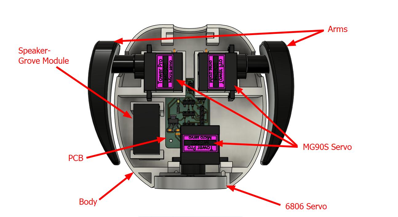
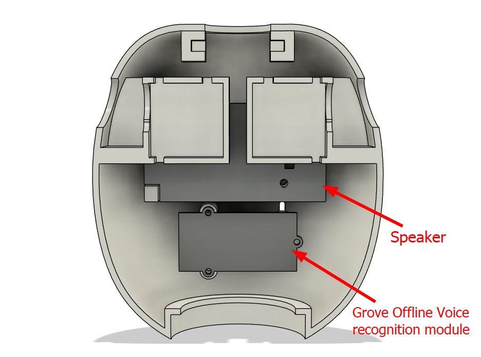
The below images shows how the toy looks and the placement of each components.
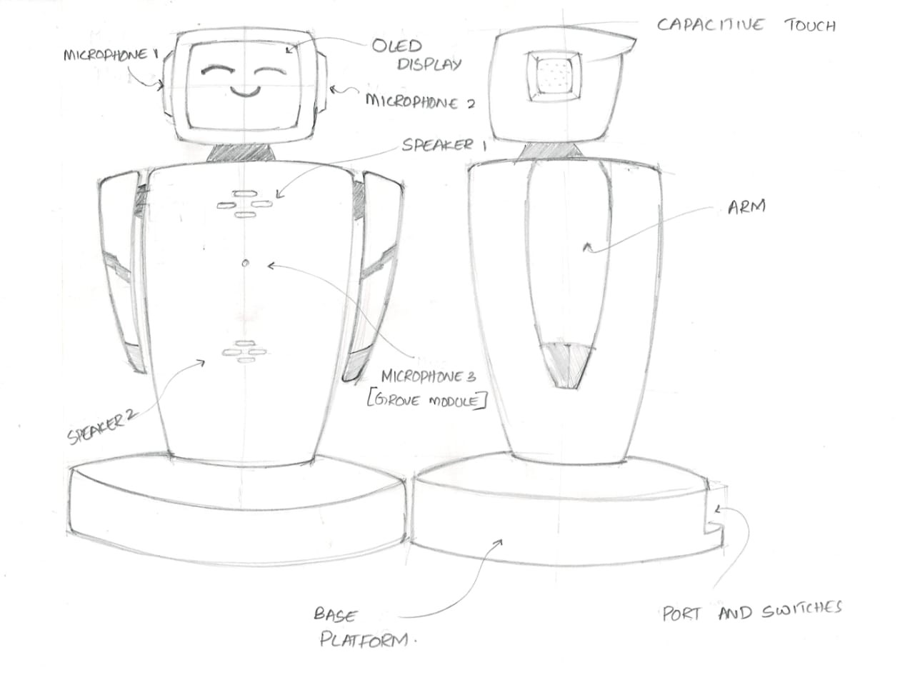
This is the finalized design of the toy. It plays audio stored on an SD card. Two microphones are placed on either side of its head to detect the direction of sound, allowing the toy to rotate toward the source. It also features a talkback function, similar to a talking toy. The arms move in sync with the MP3 playback. A capacitive touch sensor is placed on the head—when touched, the toy displays cute animations on an OLED screen and plays corresponding sounds. Additionally, song information is shown on the display.
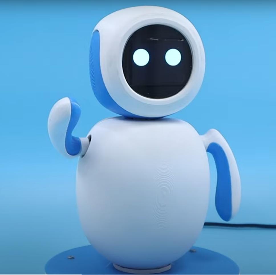
I refered many sources to get a similar product like my project and at last I found one. Its name is Eva.
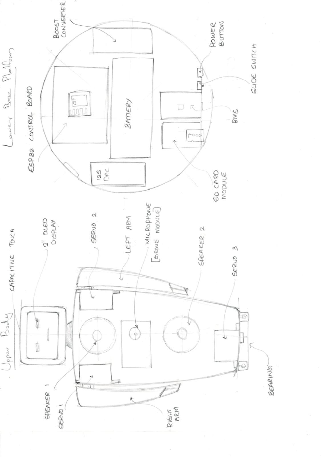
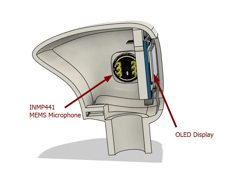
In head the toy contains 2 0.96 OLED displays, 2 INMP441 MEMS Microphones, and a touch switch as well.
The body contains most of the electronic components and here I face most difficulty to integrate all of them inside it. It contains 3 servo motors, A grove offline voice recognition module and its speaker, speaker for audio playback and the connector board as well.
 |
 |
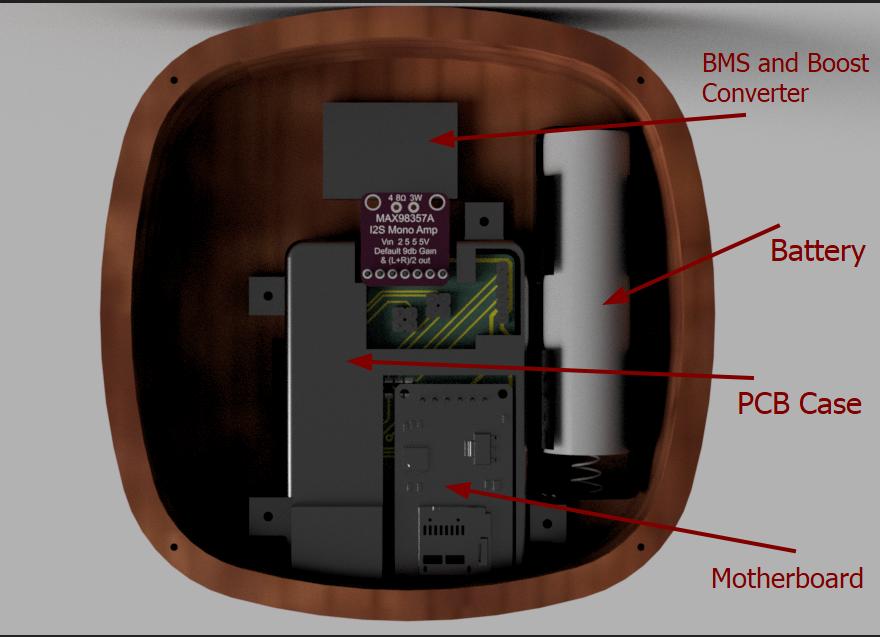
The base contains the mother board, Battery, BMS and boost converter and the holder for the bearing as well.
 |
 |
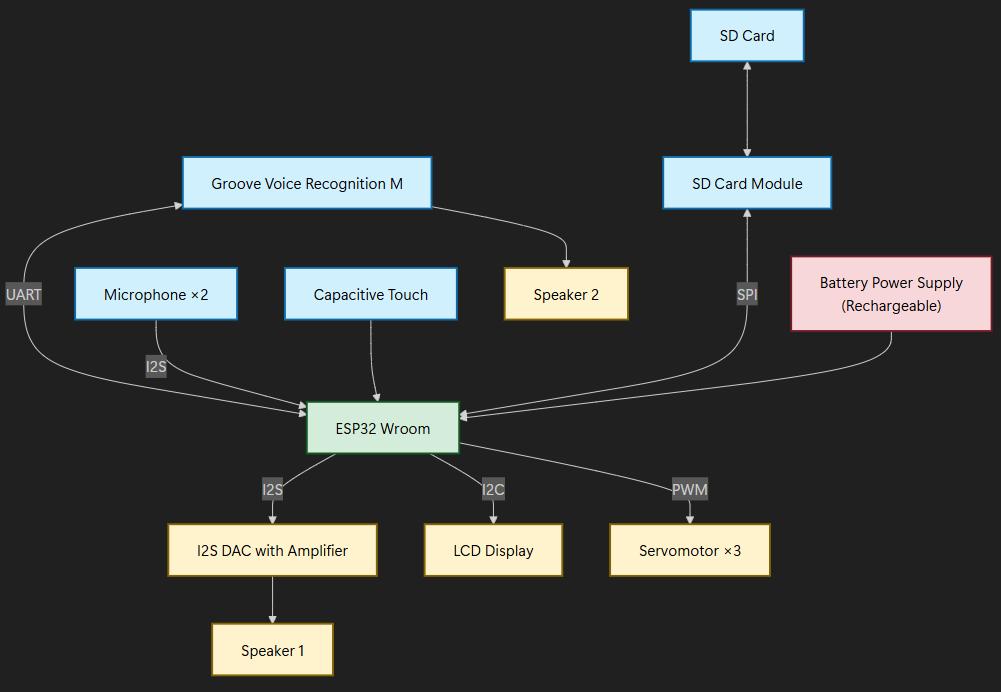
Block Diagram
This is the block diagram of the project. These all modules were included in the project. Also mentioned their communication protocol.
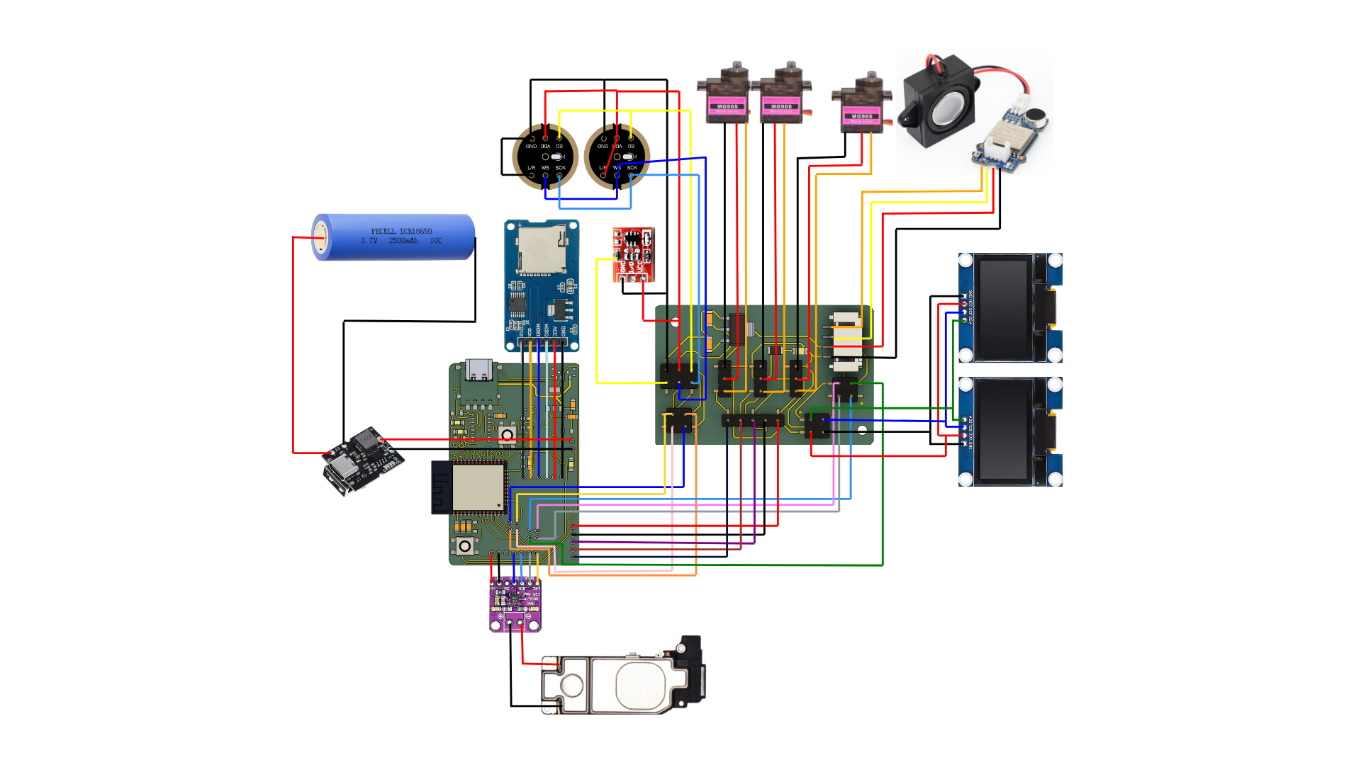
Wiring
I have 2 boards for my project a mother board and a connector board. The mother board is placed inside the base and the connector board is placed in the body. The connector only have header pins and a 3.3V regulator. The connector board is used to reduce the number of wires running down to the main board which is located in the base. Only 1 pair of power line is going up and it is then split in the connector board and the 5V is converted into 3.3V by the regulator in the connector board.
Features
- MP3 Playback from SD Card
- Talkback Functionality (Like Talking Tom)
- Voice-Controlled Commands
- Start/stop music playback
- Change tracks
- Adjust volume
- Directional Sound Detection
- Capacitive Touch Interaction
- Cute animations on an LCD display
- Fun sound effects
- Motion-Activated Arms
- LCD Display Animations
- Song Info Display
Plays audio files stored on an SD card
Records voice using a microphone and repeats it back.
Responds to voice inputs to control actions like:
Uses two microphones to detect the direction of sound and rotates it body towards the sound source.
A touch sensor on the head triggers:
Arms move in sync with the music, enhancing interactivity and realism.
Shows animations and visual effects while music is playing or touch is detected.
Displays the current song title or audio details on the LCD screen.
Fabrication Methods
- 3D Printing- Major part of the toy is going to be 3D printed.
- Laser Cutting- The covering of the LCD display is acrylic and cut using laser cutter.
- Routing- The base of the toy is made of wood and needed to route housing for the components. ShopBot or Zund needed for this operation.
- Circuit Designing- PCB designing for the toy.
- PCB Milling- manufacturing PCB for the toy.
- Soldering and Assembly- Placing the electronics components on the PCB.
- Embedded Programming- Programming the microcontroller to control the toy.
BOM
| Sl No | Part | Quantity | Unit Cost | Total Cost | Supplier |
|---|---|---|---|---|---|
| Mechanical Components | |||||
| 1 | SG90 Servomotor | 3 | 149 | 447 | Robu |
| 2 | 6806 Bearing | 1 | 750 | 750 | Amazon |
| 3 | M3 Bolts | 5 | 2.5 | 12.5 | Fab Inventory |
| 4 | M3 Threaded Inserts | 5 | 6.5 | 32.5 | Fab Inventory |
| 5 | M2 Bolts | 17 | 5 | 85 | Fab Inventory |
| 6 | Wood 130 x 130 x 28 mm | 1 | 100 | 100 | Fab Inventory |
| 7 | Acrylic Sheet 150 x 150 x 6 mm | 0.5 sqft | 125 | 125 | Fab Inventory |
| Electronics Components | |||||
| 8 | 0.96 inch SSD1306 OLED Display (128x64) | 2 | 175 | 350 | Robu |
| 9 | INMP MEMS Microphone | 2 | 198 | 396 | Robocraze |
| 10 | Iphone 7 plus speaker | 1 | 299 | 299 | Flipkart |
| 11 | Grove Offline Voice Recognition Module | 1 | 1889 | 1889 | Robu |
| 12 | Micro SD Card Reader Module | 1 | 40 | 40 | Fab Inventory |
| 13 | Micro SD Card | 1 | 398 | 398 | Fab Inventory |
| 14 | Type-C USB 5V 2A Step-Up Boost Converter | 1 | 57.99 | 57.99 | RoboticsDNA |
| 15 | ProshPlay Type C Breakout Board | 1 | 20 | 20 | Fab Inventory |
| 16 | ESP32 WROOM 32E | 1 | 250 | 250 | Fab Inventory |
| 17 | 3.6V Lithium Ion battery | 1 | 131 | 131 | Fab Inventory |
| 18 | Slider Switch | 1 | 7 | 7 | Fab Inventory |
| 19 | MAX98357 I2S Amplifier Module | 1 | 149 | 149 | Rytronics |
| 20 | Touch Switch | 1 | 30 | 30 | Local Shop |
| 21 | Capacitor 10uF | 5 | 1.9 | 9.5 | Fab Inventory |
| 22 | Capacitor 0.1 uF | 2 | 1 | 2 | Fab Inventory |
| 23 | Capacitor 1 uF | 1 | 1 | 1 | Fab Inventory |
| 24 | Resistor 10K | 4 | 0.5 | 2 | Fab Inventory |
| 25 | Resistor 500 ohm | 4 | 1 | 4 | Fab Inventory |
| 26 | Resistor 10 ohm | 1 | 1 | 1 | Fab Inventory |
| 27 | Resistor 0 ohm | 1 | 1 | 1 | Fab Inventory |
| 28 | LED_1206 | 5 | 1 | 5 | Fab Inventory |
| 29 | CH340C | 1 | 42 | 42 | Fab Inventory |
| 30 | VREG IC 3.3V 1A LDO | 2 | 28 | 56 | Fab Inventory |
| 31 | Push Button 6x6mm | 2 | 18 | 36 | Fab Inventory |
| 32 | MOSFET N-Ch SOT23 | 2 | 3 | 6 | Fab Inventory |
| 33 | Slide Switch EG1215AA | 1 | 6 | 6 | Fab Inventory |
| 34 | Conn Header Pin 02x02 | 3 | 5 | 15 | Fab Inventory |
| 35 | Conn Header Pin 01x03 | 3 | 5 | 15 | Fab Inventory |
| 36 | Conn Header Pin 02x03 | 1 | 7 | 7 | Fab Inventory |
| 37 | Conn Header Pin 01x02 | 5 | 4 | 20 | Fab Inventory |
| 38 | Conn Header Pin 01x04 | 1 | 5 | 5 | Fab Inventory |
| 39 | Conn Header Pin 01x05 | 2 | 6 | 12 | Fab Inventory |
| 40 | Conn Header Pin 01x06 | 1 | 7 | 7 | Fab Inventory |
| 41 | Conn Header Pin 01x07 | 1 | 8 | 8 | Fab Inventory |
| 42 | IDC 2x02 Connector Female | 6 | 80 | 480 | Fab Inventory |
| 43 | IDC 2x03 Connector Female | 2 | 110 | 220 | Fab Inventory |
| 44 | JST Connector 1x05 Female | 2 | 11 | 22 | Fab Inventory |
| 45 | JST Connector 1x05 Male | 1 | 5 | 5 | Fab Inventory |
| 46 | PCB Single Side | 1 | 100 | 100 | Fab Inventory |
| 47 | PCB Double Side | 1 | 150 | 150 | Fab Inventory |
| Total | ₹6806.49 | ||||
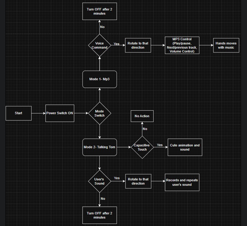
User Flow Diagram
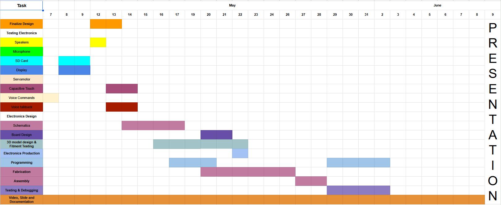
Project Schedule
Conclusion
This week, I focused on system integration by understanding how different components work together within a project. I finalized my project design and completed the Bill of Materials (BOM), ensuring everything aligns for smooth integration.