Week 7 – Computer-Controlled Machining
This week is about learning how computer controls machine tools to cut, drill, mill or shape materials automatically.
The objective is to first design a 3D object in CAD software, then use a CAM software to create a toolpaths (G-Code), then do Machine setup, and lastly perform machining.

AI prompt ChatGPT: "Can you give me a animated image of myself giving G-code to CNC machine, this week is about designing a 3D object in CAD software, then use a CAM software to create a toolpaths (G-Code), then doing Machine setup, and perform machining work."
Assignment Overview
- Do the lab's safety training
- Test runout, alignment, fixturing, speeds, feeds, materials, and toolpaths for your machine
- Make (design+mill+assemble) something big (~meter-scale)
- extra credit: don't use fasteners or glue
- extra credit: include curved surfaces
- extra credit: use three-axis toolpaths
| Day | Activity | Status |
|---|---|---|
| 🛠 Thursday | Class - Computer Controlled Machining & Group Assignment | Completed |
| 🛠 Friday | Individual - 3D Designing | Completed |
| 🛠 Saturday | Remake 3D design -> Parametrically Scalable Model | Completed |
| Make a downscale model using cardboard | Completed | |
| 🛠 Sunday | Machine-setup, generate G-Code and Plywood Machining/Cutting | Completed |
| 🛠 Monday | Post-Procession | Completed |
| Assembly and Testing | Completed | |
| 📘 Tuesday | Documentation and Regional Review | Completed |
| Revisit global class recording and class notes | Completed | |
| 📘 Wednesday | Group assignment Documentation | Completed |
| Work on Final Project-page and HTML of About me page | Pending |
Group Assignment
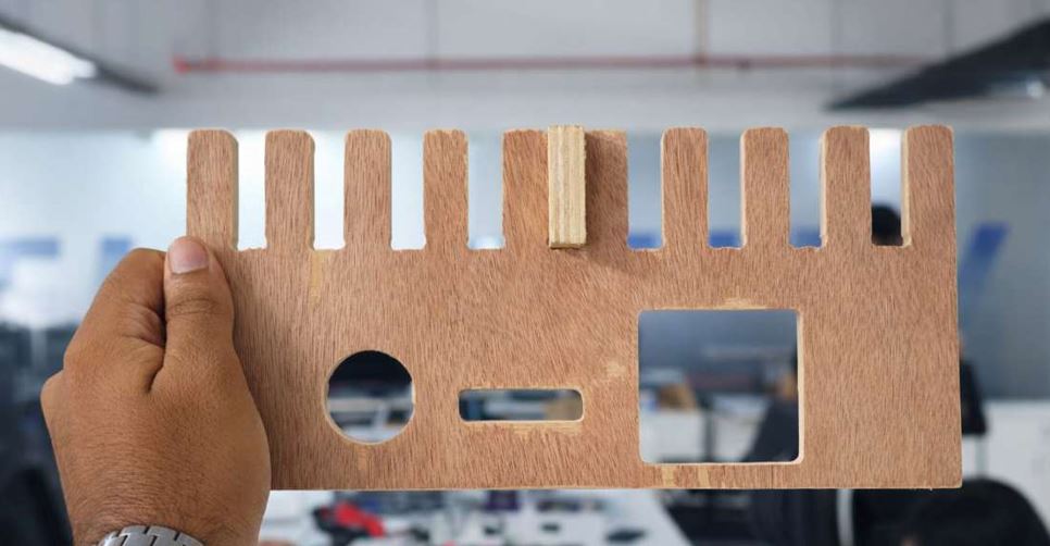
In our group assignment, we learned about the necessary safety equipment and precautions for operating the machine and post-processing. We then designed a jig with varying values to accurately measure the machine's runout. After testing the feed and speed rates, we created CAM toolpaths using VCarve software. Finally, we post-processed the jig and determined the runout value to be Ply_thickness - 0.1mm.
3D Designing
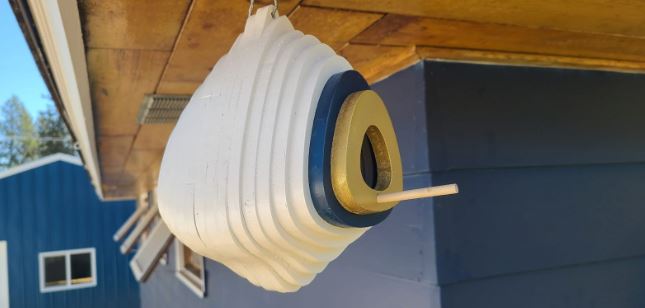
First, I decided to make bird nest but after discussing with my instructor - the bird nest may not fulfill the dimensional criteria of meters scale object of the week's assignment and also I may not learns joints in making bird nest, thus I decide to make something else.
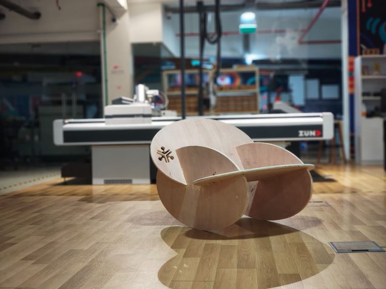
Then I explored furnisher projects from ShaperHub and I find an inspiration rocking chair and I decide to make that chair. The design was very minimalist but technically it involved concept of center of gravity center of gravity and balancing.
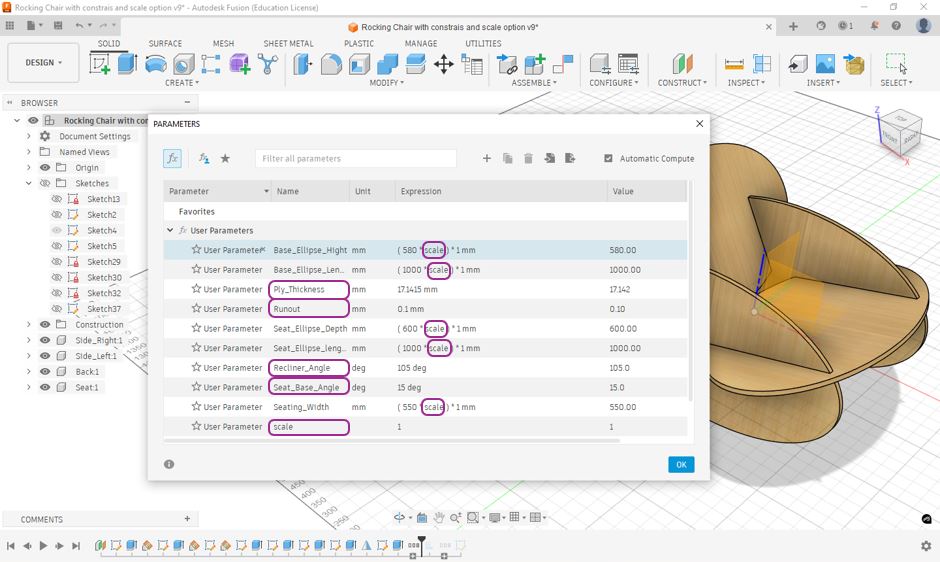
As this was a big design our instructor as informed us that before cutting the design on the wood at full scale we need to cut the design on cardboard and test the downscaled model thus we need to make the 3D design in using parametric so that we can downscale it and test it on cardboard. Thus I gave below parameter as I progressed through my 3D design.
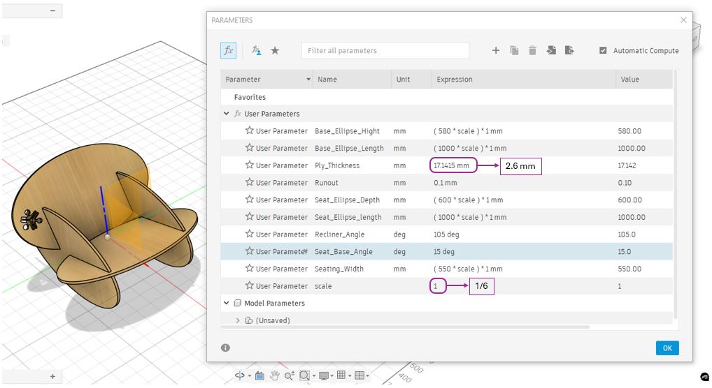
Here, a few important parameters are Ply_Thickness which varies and depends on quality of Plywood and more importantly at the time of downscaling the model this value we need to replace with cardboard thickness. Then, Runout is the factor that we got from our group assignment. This is the access material that spindle and tool remove due to alignment. Thus this value is reduced from the thickness of plywood in order to get accurate cut. Seat_base_Angle and Recliner_Angle are angle that I defined for seating comfort. and most important is the scale, I can change the scale to for example 1/6 to downscale the model and cut on the cardboard. we can see that scale does not have any unit and I have multiplied with all the parameters except - ply_thickness, runout, Seat_base_Angle and Recliner_Angle.
Steps that I followed to make this design are first I made one of the side ellipse and constructed two planes at 15° with horizon and called it Seat_base_Angle plane and 105° degree and called it Recliner_Angle, then constructed ellipse on these two planes extruded them with ply_thickenss. After that I used Projection operation to make the joints between these ellipse. and lastly I used the Mirror function to mirror the side ellipse.
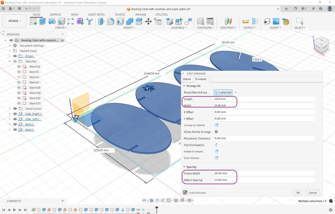
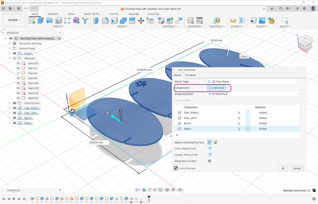
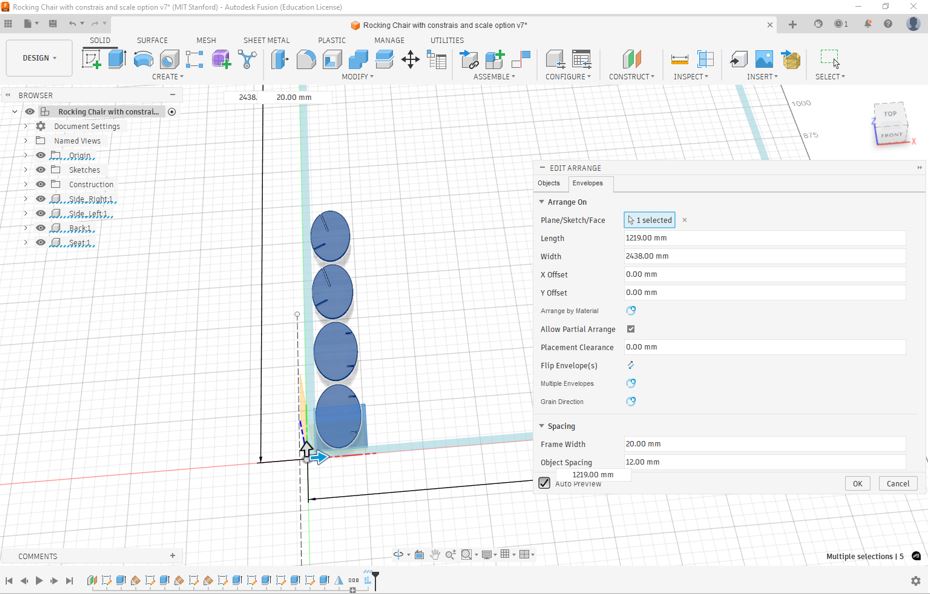
Unlike leaser cutting week when I made my fusion design in single body and thus I was not able to use arrange function, this time I made design in assembly so that each part appeared as individual body and thus I can use arrange function to arrange the assembly part in a single plane of plywood's overall dimensions that for my case is 1219mm X 2438mm (4ft X 8 ft). A few other things that need to be taken care is while using arrange function is Frame width and Object spacing, I defined frame width 20mm thus fusion will leave 20mm space from each side and then arrange the components, thus when this operation is executed by CNC router it will not cut on edges of the plywood. The object spacing should be more than twice of the tool dia meter because the tool will pass twice between the two components. Secondly, select all the components that need to be arranged in the defined frame size.
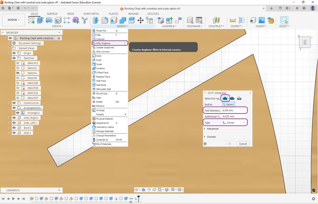
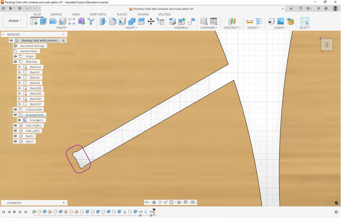
Then, I applied the Nifty Dogbone function. This is important to apply dog born type curves at the joining corners so that to components properly fits with each other. Nifty Dogbone is a plug-in to Fusion 360 that allows 30 days free trial. Click on Modify >> Nifty Dogbone >> select bodies >> Enter Tool diameter >> Types - Corners >> Ok . In my case, I was using 6mm tool thus I entered 6 mm as tool diameter. This will automatically apply Dogbone shape at the corners of the components.
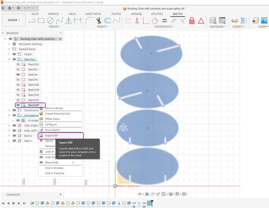
At the last, I used Projection function to create sketch of all four components to do this first select any one component press "p" >> select remaining 3 components >> ok now we will see a new sketch created under sketches. Now, we can Right click on sketch >> Export DXF. Later while machining we can import this DXF file in Vcarve Pro software of ShopBot Machine.
3D Model Viewer
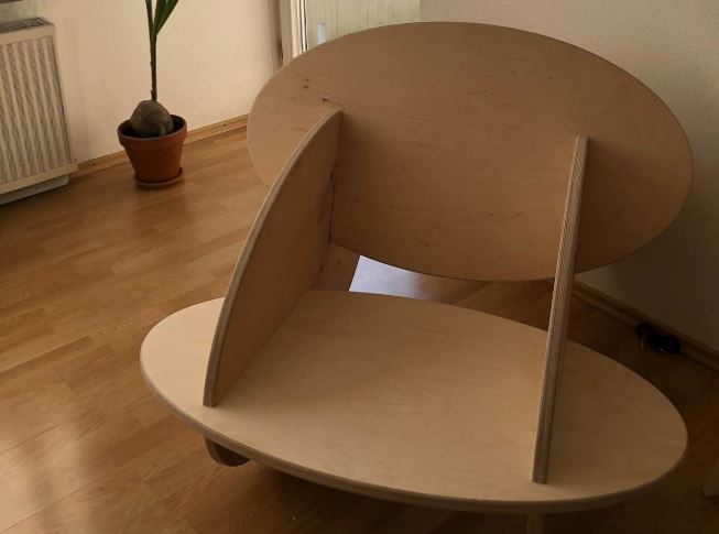
Testing on Cardboard
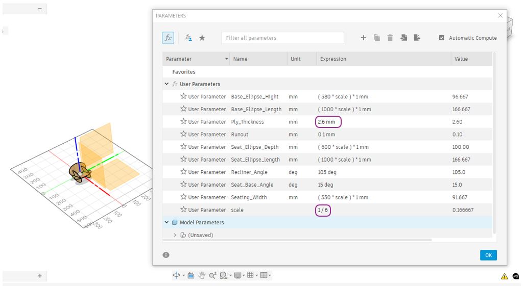
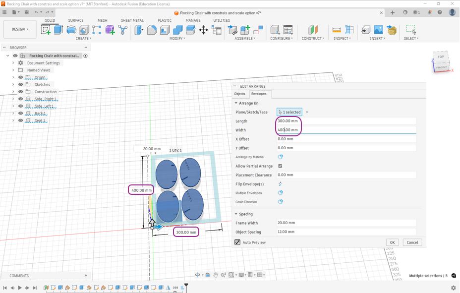
Downscaling - This is where making design parametric is very helpful, by changing the scale in my defined parameter I was able down scale my object by 1/6. The Ply_Thickness shall be changed with Cardboard Thickness.
My learning - Ensure that all bodies in the 3D model are properly constrained with respect to center of assembly and X, Y and Z movements. If they are not constrained, scaling the model will cause the bodies to remain in their original positions instead of scaling together as a single assembly, making the parts appear separated.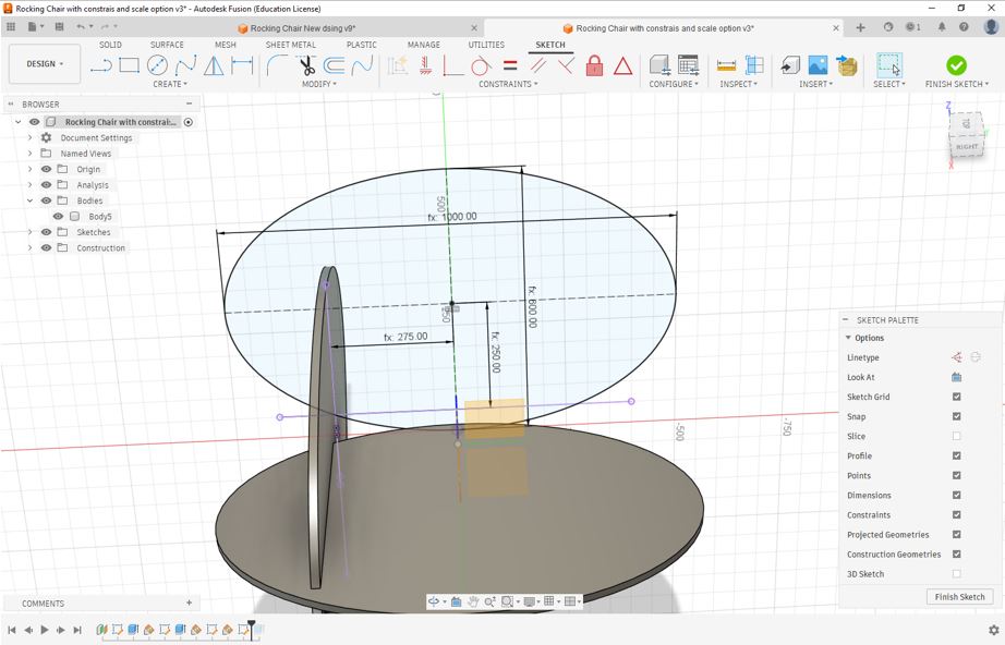
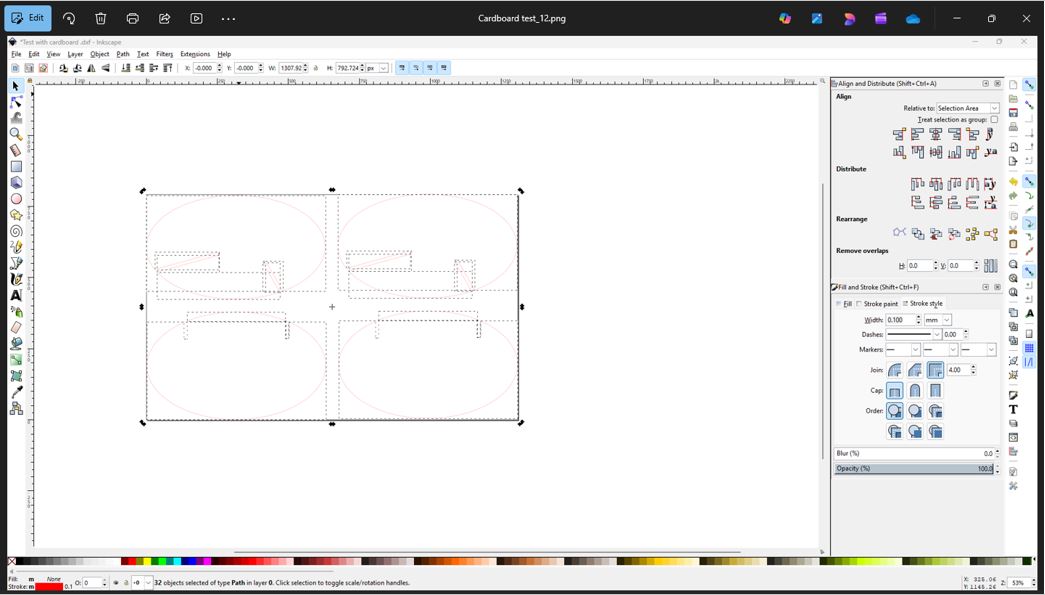
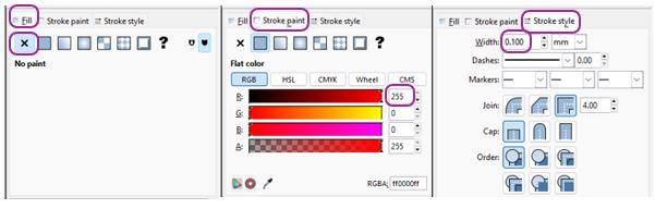
I generated the DXF file from fusion, Imported DXF file into Inkscape and updated the Fill as No Fill and Stroke as 255 (RED) and stroke width 0.1mm. Then, I used Trotec speedy 100 laser cutting machine machine to cut the cardboard. In the Trotec software, I kept the power as 80% and speed 3. (please refer my documentation from Computer-controlled cutting to learn more about laser cutting and related parameters).
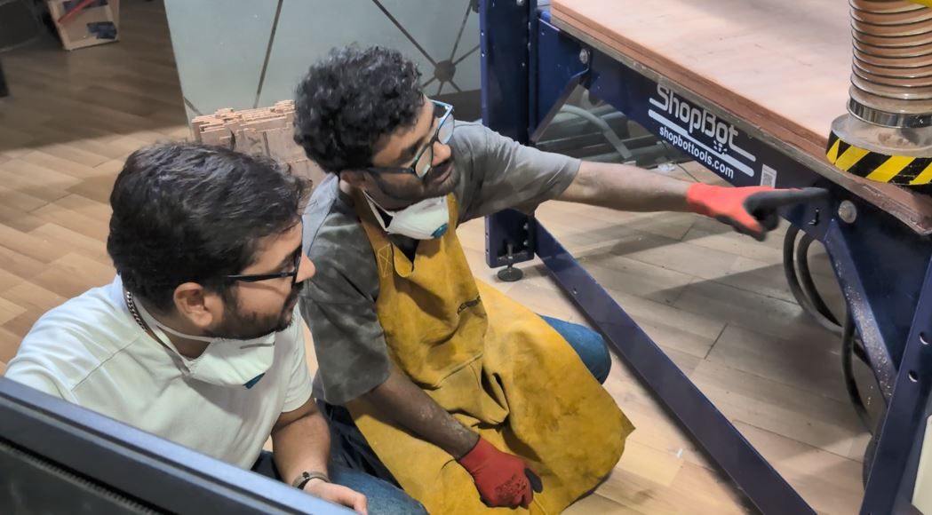
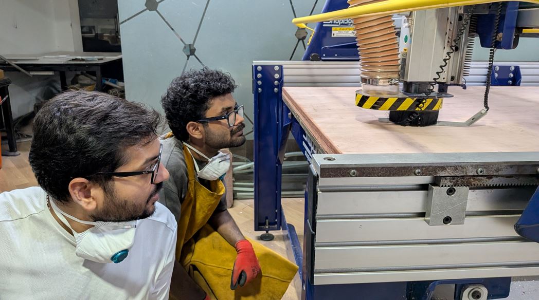
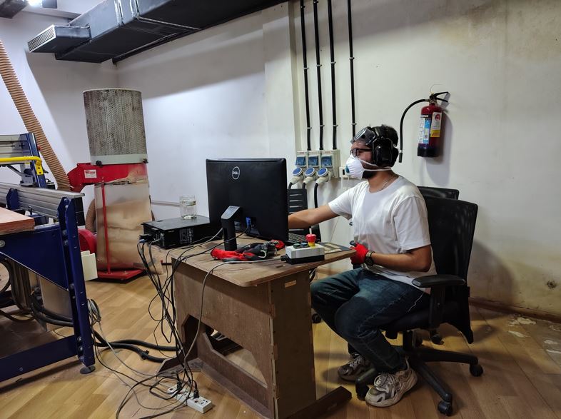
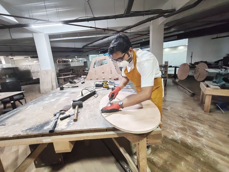
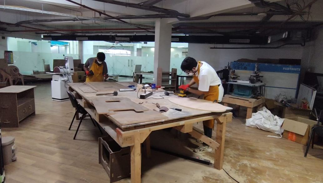
Machine Set-up and Cutting
Before starting machining, it is very important to be vary
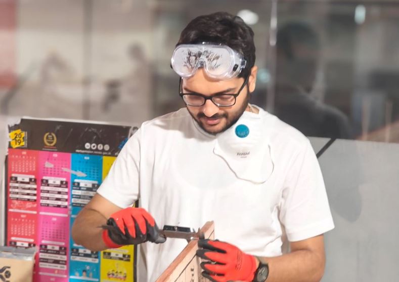
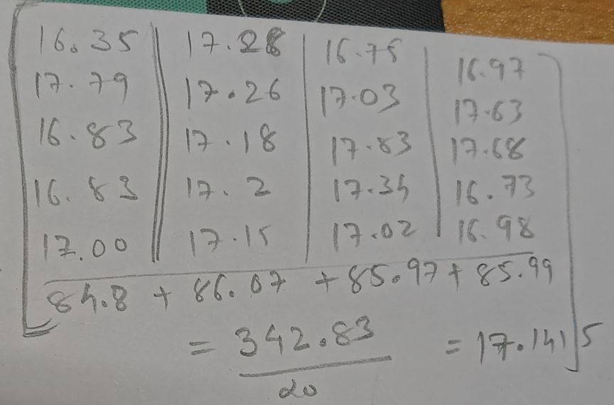
First of all, we need ot measure the thickness of the plywood that we are going to machine. I took about 20 reading, 5 from each side of the ply to get more accurate value, the Ply_Thickness was 17.1415 mm and I updated this value in to my Fusion parameters and also entered the Runover value of 0.1 mm exported the DXG from the fusion model.
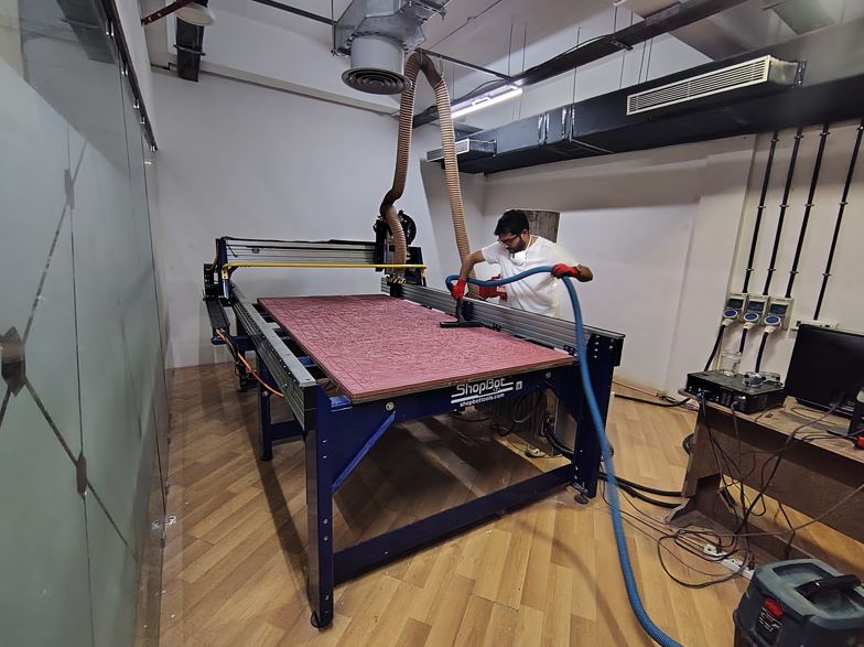
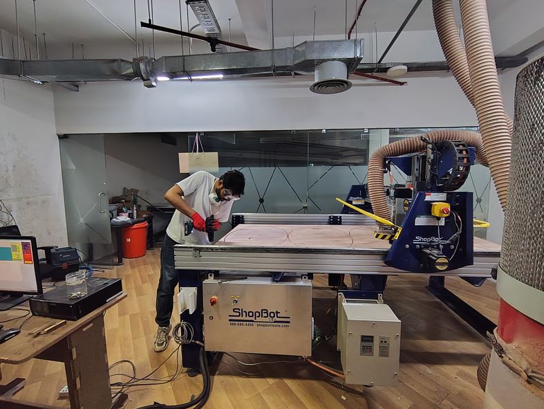
Next, I placed the Plywood on the top of sacrificing layer of the Shopbot machine.
Next, I vacuumed the sacrificial layer, as it is important to remove any wood chips or dust. These particles can create an uneven surface, which may lead to improper zeroing of the machine.
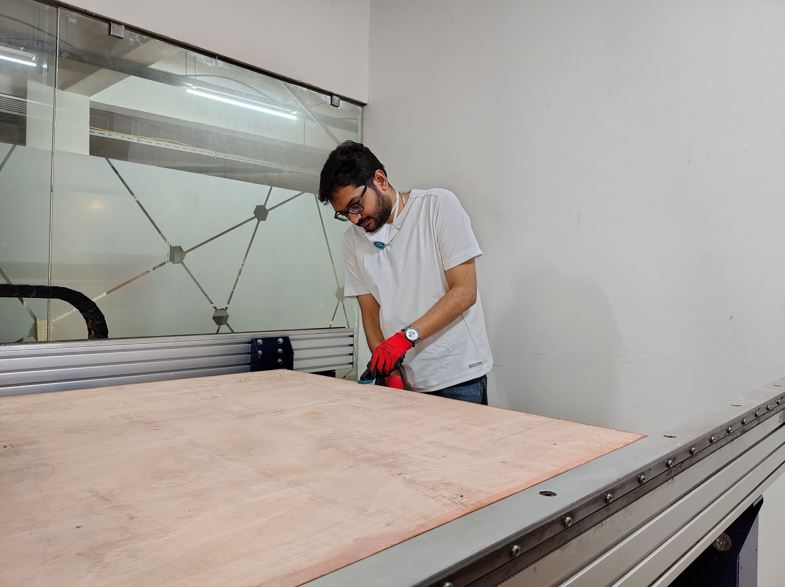
I aligned the plywood corners with the sacrificing layer and clamped it.
Next, we need to select the screwing location in the VCarve Pro software.
My learning : We can manually screw the plywood to the sacrificial layer, but doing so carries the risk that the cutting tool may collide with the screws, which can potentially damage or break the tool To avoid this, it is better to define the screw locations in the CAM software. This allows us to verify the toolpath before starting the main cutting operation, ensuring that the tool does not intersect with the screw positions.
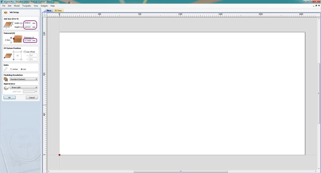
In the VCarve Software, first I entered the Plywood X and Y dimensions and its thickness.
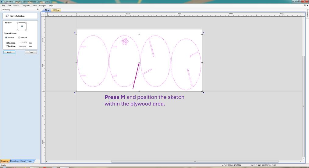
Press M and move the sketch to the center of the workpiece area.
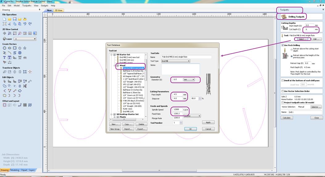
Now to do drill operation I selected the Drilling Toolpath entered drilling depth as only 6mm, so that screw gets grip with the plywood. Select the tool FAB END MIll (6mm) single >> Enter tool diameter 6mm >> Pass Depth 4.5mm >> Stepover 4.8 mm >> Spindle Speed 12000 r.p.m >> Feed Rate 1200 mm/min. There parameters depends on the tool datasheet, workpiece material and past observations.
Then using Draw circle tool I drew six screwing locations of 6 mm dia and then clicked calculate.
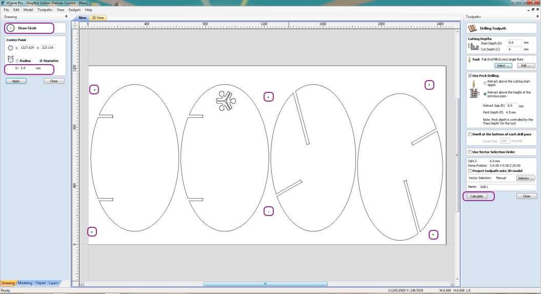
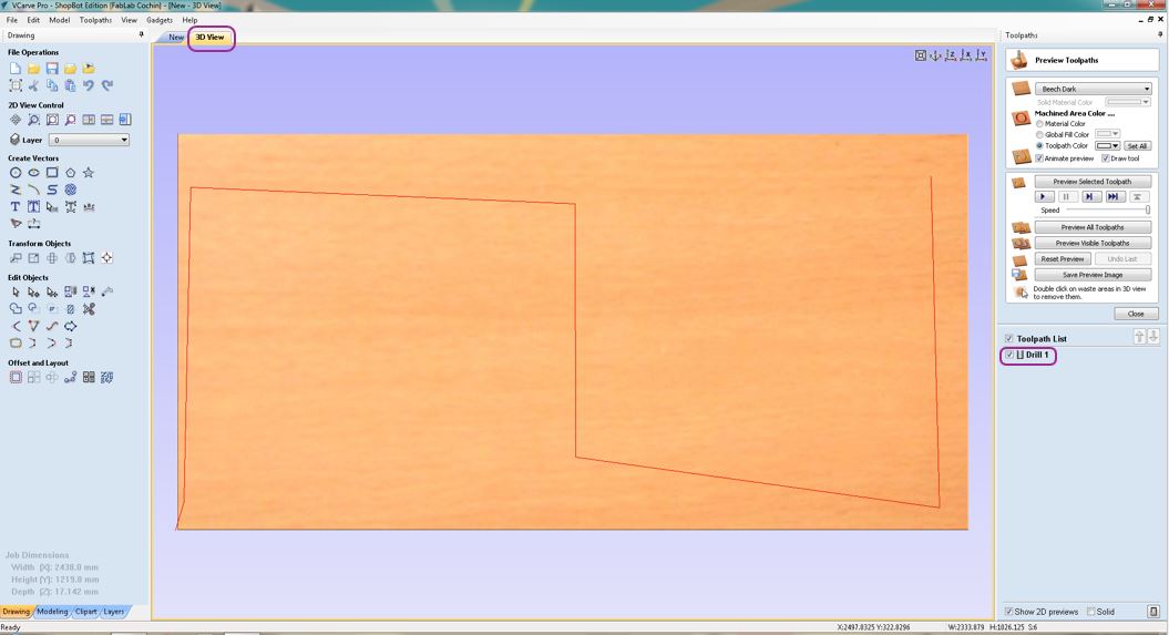
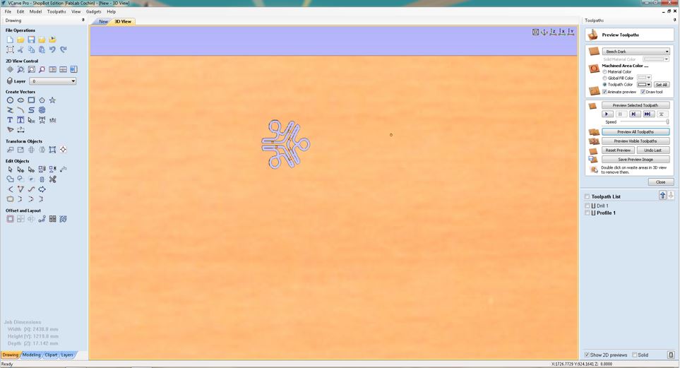
Now In the 3D View, we can see the tool path updated on the workpiece.
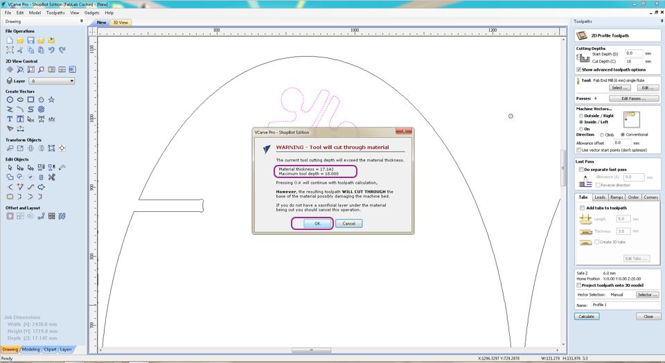
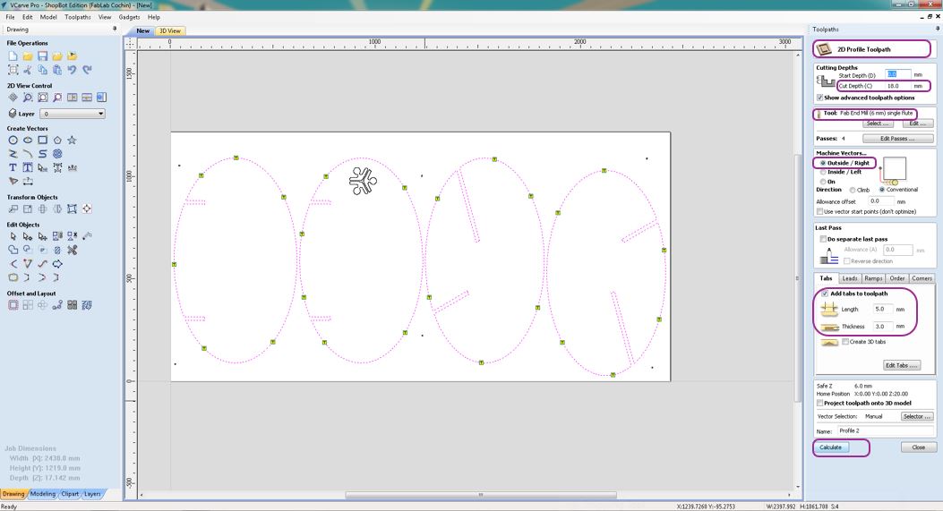
Next I selected the 2D Profile Toolpath to cut the Super Fablab Kerala logo from the inside cut operation. Before doint this please make sure that the curves/sketch Vector lines are connected as one single line, otherwise we can use Join Vector with smooth curve tool to select then and connect them. Next I gave 18mm cut depth and selected inside cut operation and calculate.
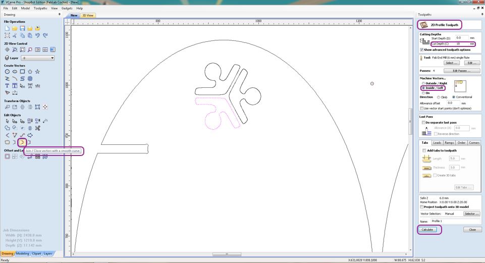
Here I gave Cut Depth > 17.1415 mm to ensure that the ply is cut through properly because it was having uneven thickness at various locations.
Using add tabs, we can add small tabs that holds the inner cut material. Otherwise while cutting operation it can move and collide or come on top of the workpiece.
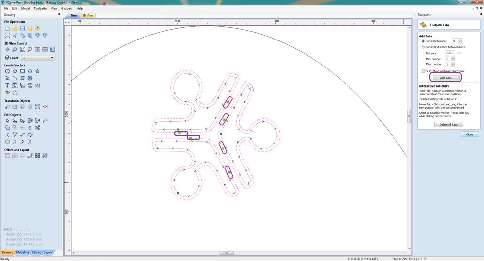
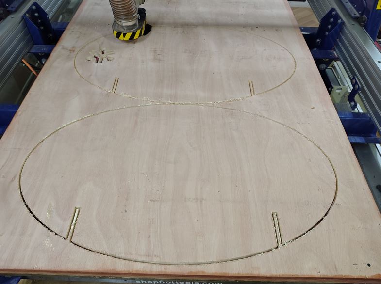
Then, I added Profile Toolpathoperation and gave 18 mm cut depth and selected Outer cut so that ir cuts from outside of my 3D object's bodies and added Tabs with dimension length 5 mm and thickness 3 mm.
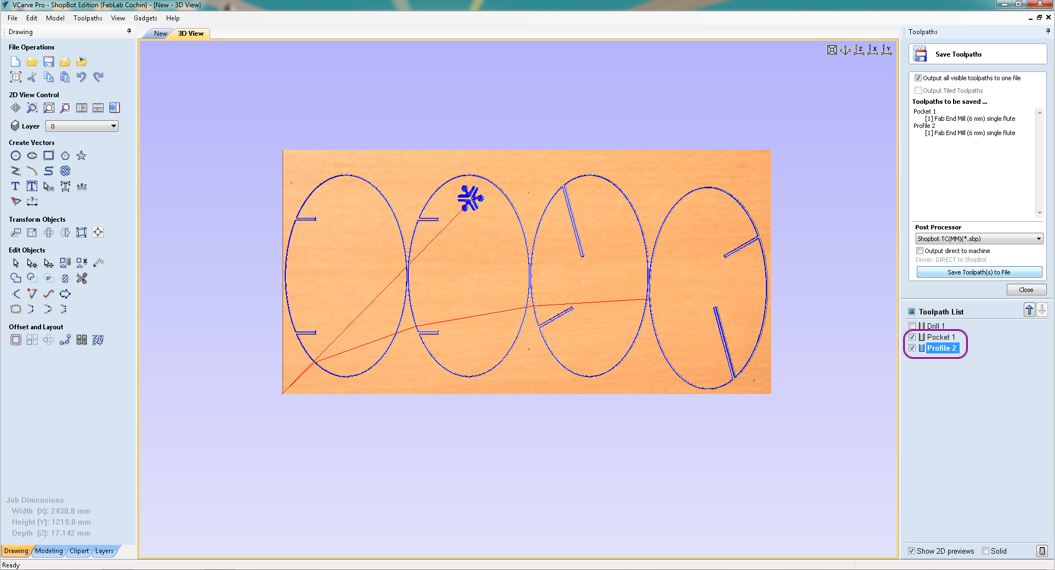
Here, we cna see three different cutting paths - Drill Path is for screwing the workpiece, Pocket Path is for cutting the FABLAB kerala logo and Drill Path is for cutting the main bodies of the assembly.
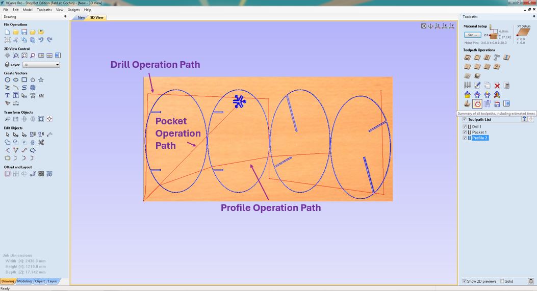
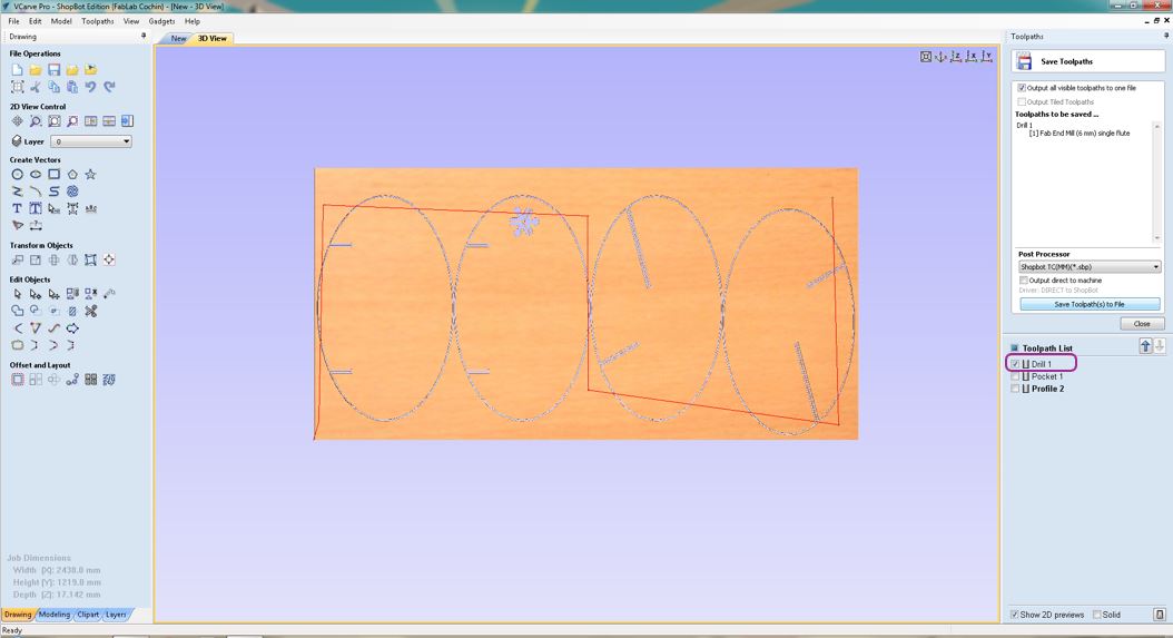
We need to separate the Drill path with other paths, so that we can only run first G-code of Drill operation and fix the screws and then run the G-code of Pocket Operation and Drill Operation.
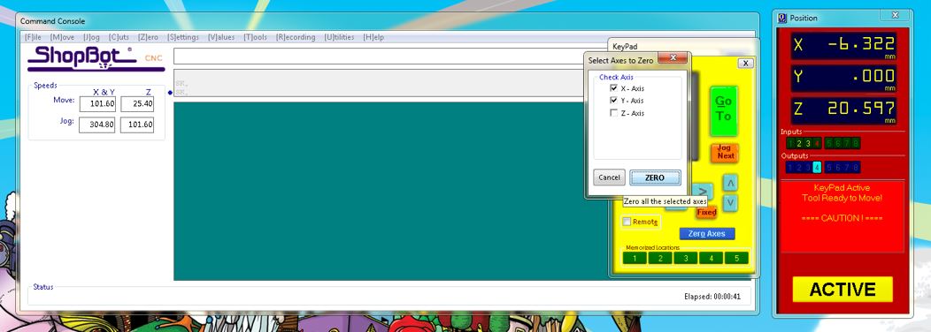
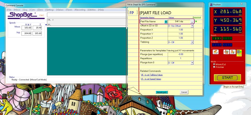
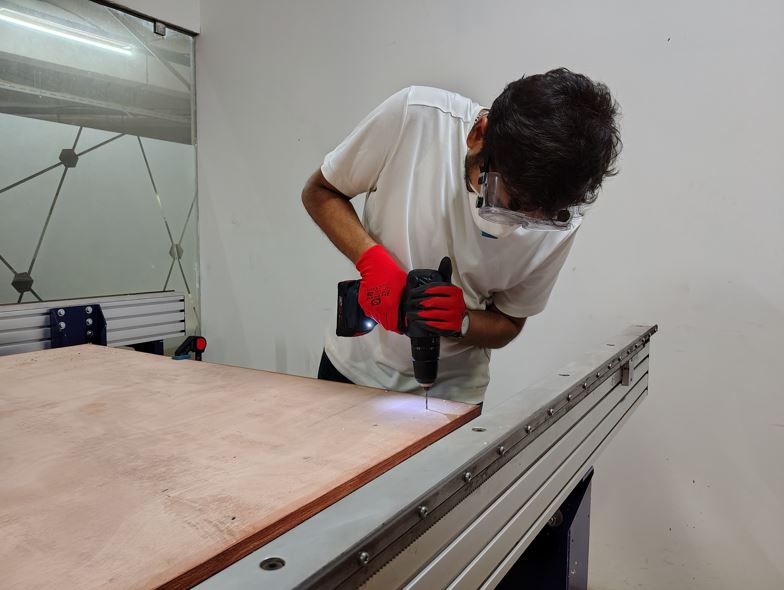
Now, I open the command console of the ShopBot machine and set the X zero and Y zero, and Z zero using alligator pin and aluminum plate and it automatically reduces the thickness of aluminum plate from the Z zero settings.
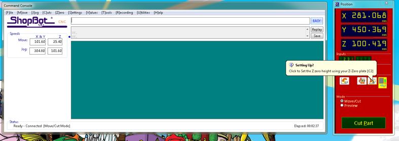
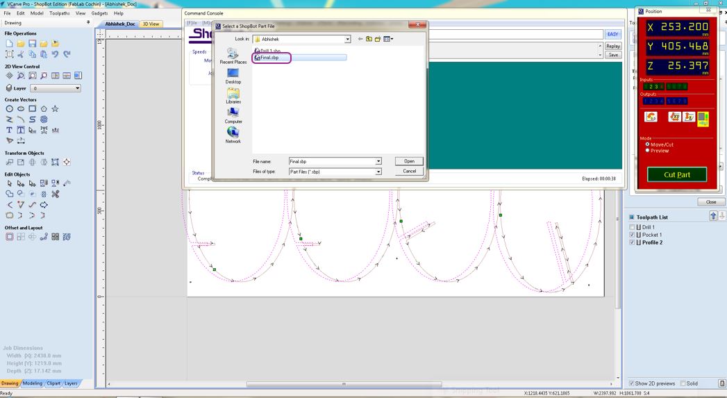
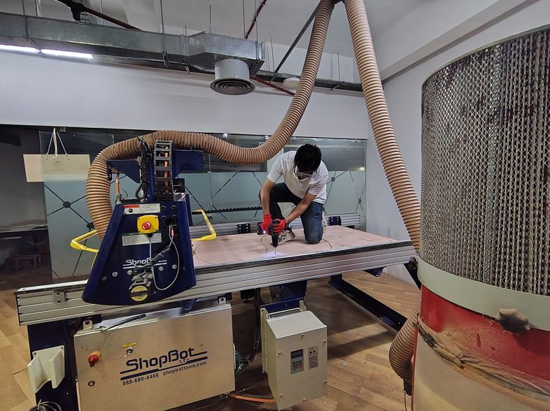
After performing X zero, Y Zero and Z zero settings, I executed G-Code of Drill operation by File >> Open >> Drill1.sbp file >> Start.
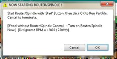
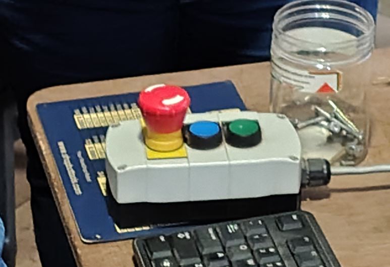
Below is very important, we need to start the router with the manual start button and then click ok, otherwise the ShopBot will understand that the router is rotating and it will start moving the tool even if spindle is not rotating.
Then I drilled through plywood and screw the plywood to sacrificing layer at all 6 selected locations.

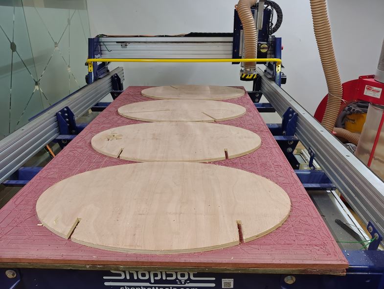
Then, run the final operation G-code of pocketing and cutting final bodies.
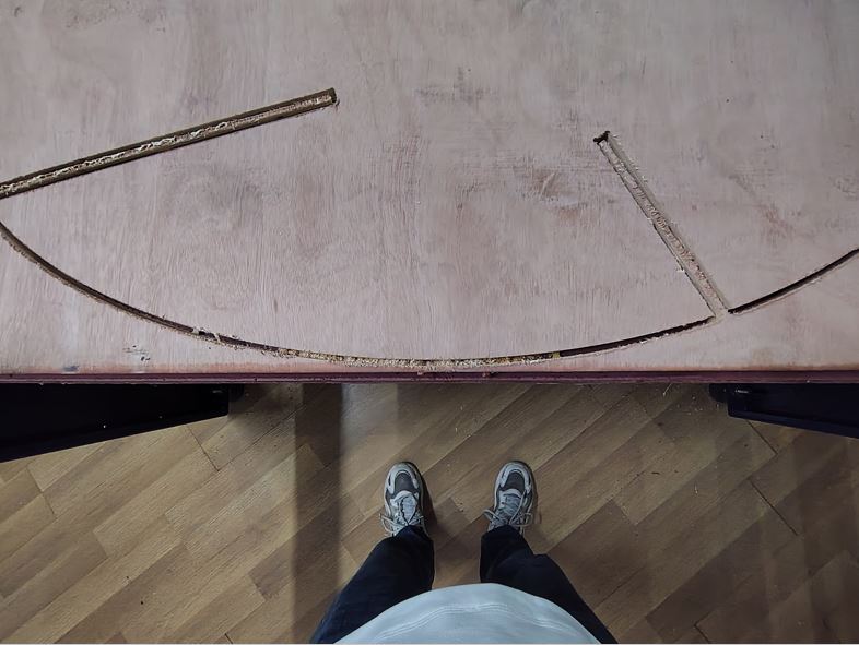
Now, I moved the spindle up and then moved away from the screws and removed the screws.
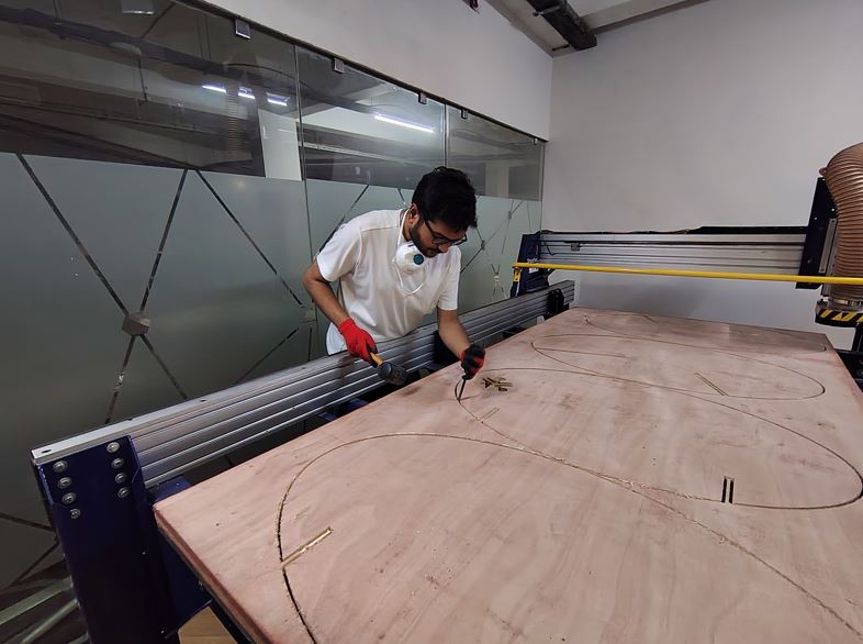
Now, I braked the tabs with chisel and hammer and moved the workpiece out of the ShopBot.
Post-processing and Assembling
Very first thing is to remove Tabs using chisel and hammer.
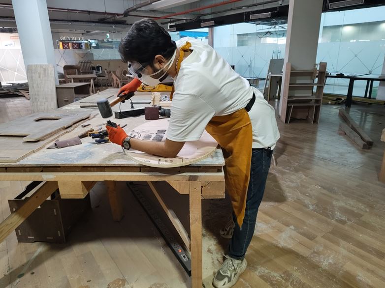
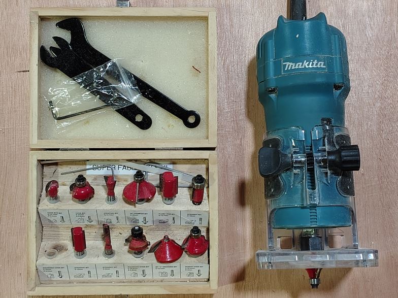
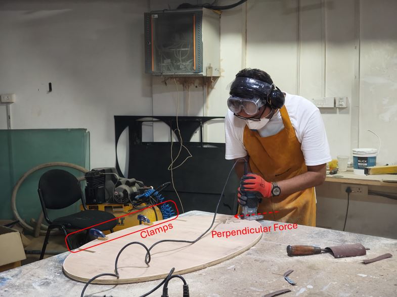
Then, I did manual routing to round the corners of seat and back rest ellipses because these are corners where we have user touch points.
I used half round file to file the curves of Fablab Kerala logo and regular file to file the edges of the Base ellipse which will be in contact of the ground so that it can swing smoothly.
Now, I tried to assemble but it was very tight and did not assemble.
My learning: Initially, I did not sand the flat mating surfaces of the ellipses, which resulted in a very tight press-fit and prevented the parts from being inserted into each other. My instructor advised sanding all four ellipses, which meant preparing eight contact surfaces in total. Sanding helped remove the surface irregularities and thickness variations of the plywood, improving dimensional tolerance and making the press-fit assembly feasible.
Additionally, I had not added chamfers at the edges of the intersection slots during the design stage. Because of the sharp edges, the ellipses could not easily slide into each other during assembly. To solve this issue, I manually created small chamfers using a hand file, which eased the insertion process and improved the overall assembly fit and alignment.
Finally, after sand and a lot of filling the matting cuts and lastly hammering we were able to fit the four ellipse together.
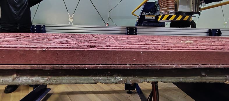
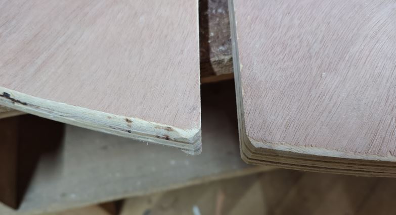
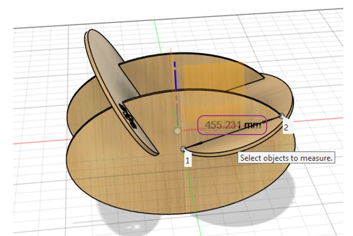
We realized that the Ply_Thickness is the issue, it has a lot of variation as we can see in the below image it ranges from 16.35 mm to 17.79 mm, this more than 1.3 mm variation makes it harder to depth of 455.5 mm.
Testing
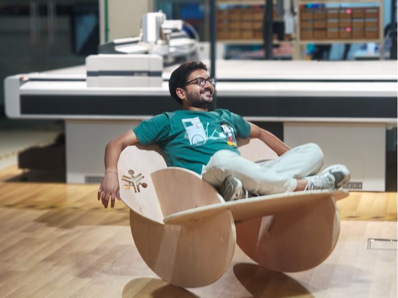
Approved!
Hero Shot
✨ Key Learnings This Week
- Ensure that all bodies in the 3D model are properly constrained with respect to center of assembly and X, Y and Z movements. If they are not constrained, scaling the model will cause the bodies to remain in their original positions instead of scaling together as a single assembly, making the parts appear separated.
- We can manually screw the plywood to the sacrificial layer, but doing so carries the risk that the cutting tool may collide with the screws, which can potentially damage or break the tool To avoid this, it is better to define the screw locations in the CAM software. This allows us to verify the toolpath before starting the main cutting operation, ensuring that the tool does not intersect with the screw positions.
- Initially, I did not sand the flat mating surfaces of the ellipses, which resulted in a very tight press-fit and prevented the parts from being inserted into each other. My instructor advised sanding all four ellipses, which meant preparing eight contact surfaces in total. Sanding helped remove the surface irregularities and thickness variations of the plywood, improving dimensional tolerance and making the press-fit assembly feasible
- We observed that the plywood thickness was the main issue. The thickness varied significantly across the sheet, ranging from 16.35 mm to 17.79 mm. This variation of more than 1.3 mm makes it difficult to achieve a consistent slot depth of 455.5 mm, which directly affects the fit and alignment of the assembled parts.
Reflection
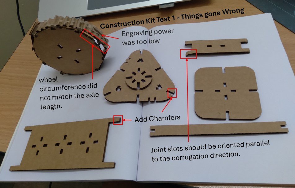
This week made me reflect on my approach to design compared to Week 3. During Week 3, my engineering mindset pushed me toward over-complicating the design. I attempted to create rotating wheels and additional mechanisms within a 2D design, which made the model unnecessarily complex. Although the assignment requirements were technically satisfied, the design became difficult to assemble and I was unable to properly fit the grips in the final assembly.
In contrast, this week I deliberately chose a simpler and more practical design approach. Instead of over-engineering the solution, I focused on creating a simple and functional object. By keeping the design minimal and applying only a small amount of engineering logic, particularly considering the center of gravity, the final result worked much better than expected.
This experience reminded me that effective engineering is not always about complexity, but about choosing the simplest solution that works reliably. A thoughtful application of basic engineering principles can significantly improve the functionality of even a simple design.