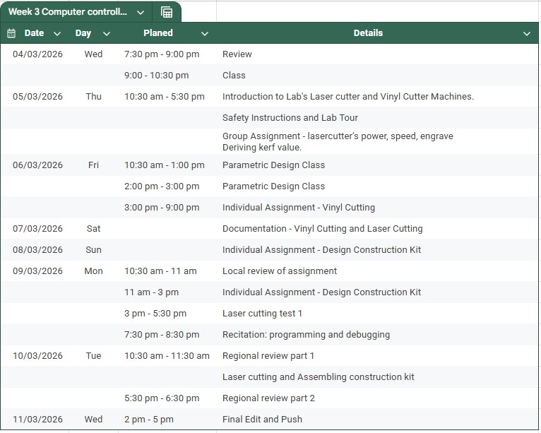
Week 3. Computer-Controlled Cutting
This week is focused on computer controlled cutting and below are the assignment points.
- Group assignment:
- Do your lab’s safety training
- Characterize your laser cutter’s focus, power, speed, rate, kerf, joint clearance and types.
- Document your work to the group work page and reflect on your individual page what you learned.
- Individual assignments
- Cut something on the vinyl cutter.
- Design, lasercut, and document a parametric construction kit, accounting for the lasercutter kerf.
- extra credit: design it to be assembled in multiple ways.
- extra credit: include elements that aren't flat.
- extra credit: engrave as well as cut.
Group Assignment
As part of our group assignment, we received safety training on operating the laser cutting machine.
- When machine is under operation, never leave the machine alone.
- If operating alone in the lab, then always inform someone to keep periodic check or even call every few hours to check if I am doing good (if operating risky machines such as laser cutting ot CNC wood milling ).
- Know the location of lab's first aid box, and maintain essential things in the first aid box.
- Know the location of lab's fire extinguisher and take nessesorly trainings to operate it.
- Always ware safety equipments whenever is nessesorly such as hand gloves, eye protector, earplugs, masks or even helmet.
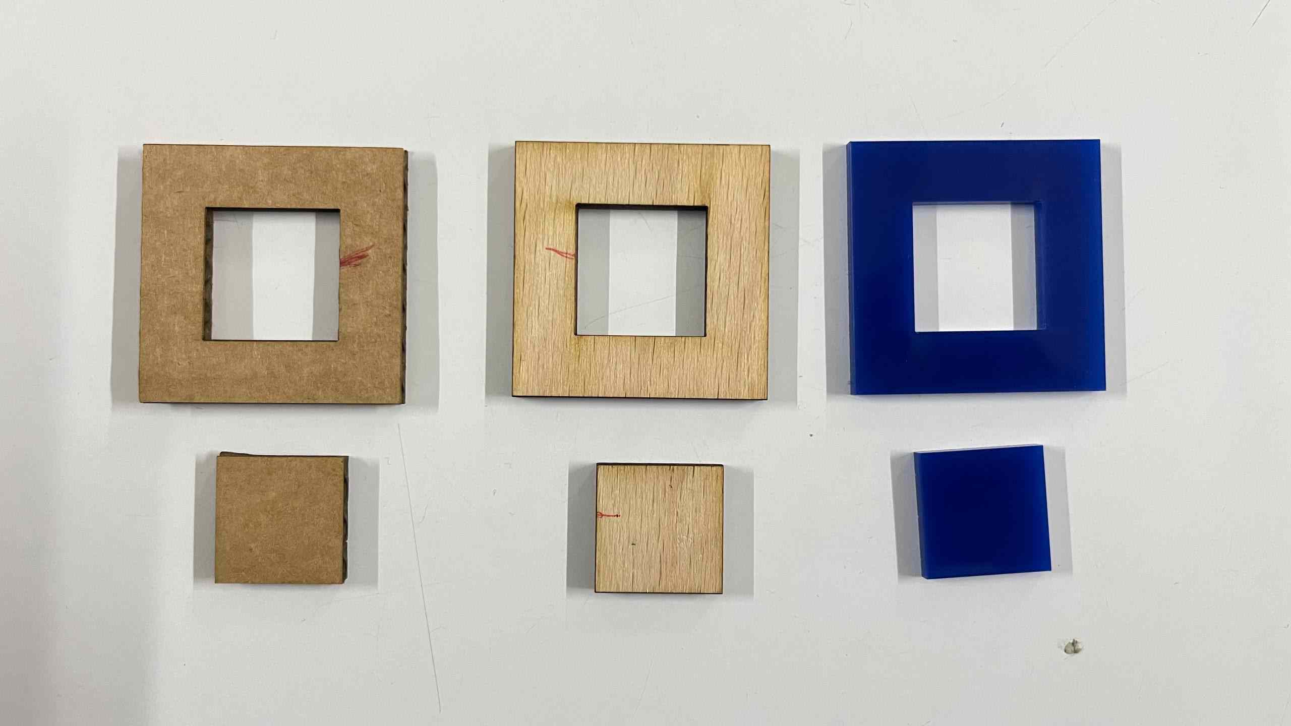
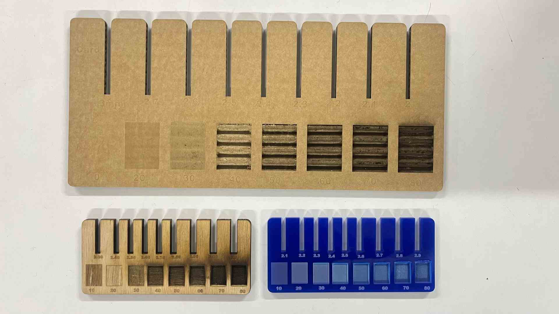
We also conducted kerf tests on different materials to determine precise values for achieving tight and reliable press-fit joints. My reflection of lab safety training is as below:
Kerf for 3mm thick cardboard = 0.3 mm
Compression value for 3mm thick cardboard = 0.2 mm
The effective kerf for wood and acrylic was :
Kerf for wood = 0.14 mm
Kerf for acrylic = 0.1 mm
Computer-Controlled Cutting [Overview]
It means a machine that is controlled by a computer using digital design files, instead of being operated by hand manually turning wheels and levers to cut. It is called CNC - Computer Numerical Control.
In simple words: A computer tells the machine exactly where to move, how fast to move, and how deep to cut — with high precision and repeatability.
Process Workflow:
- Design (CAD): You create a 2D or 3D model of your part using Computer-Aided Design software (Such as Fusion 360, FreeCAD, Blender for 3D, and Inkscape for 2D, CAD file like SVG, DXF)
- Translation (CAM): You convert that design (SVG and DXF) into "G-code" using Computer-Aided Manufacturing software. This G-code is the language the machine speaks.
- Execution: The CNC machine reads the G-code and moves the cutting tool along various axes (X, Y, and Z) to carve the part out of a solid block of material.
AI Prompt : What is computer controlled CNC?
Vinyl Cutting Machine
Vinyl cutting is a digital fabrication process that allows us to cut 2D designs and vector graphics from vinyl sheets. A vinyl cutter uses a tiny computer-controlled blade (like a super sharp pen) to cut thin materials such as:
- Vinyl sheets (stickers, T-shirt heat transfer)
- Thin films (copper)
Process Workflow: we give it a vector design → the mods CE converts it to machine instructions → the blade moves in X-Y directions → it cuts only the top layer → you peel away extra material.
In our lab, we use a Roland CAMM-1 Servo desktop vinyl cutter. Our technical instructor, Mr. Saheen, introduced us to its working principles, common applications, and operating process. The machine uses a computer-controlled blade mounted on a CNC linear motion system (moves alongside of X axes). The blade can freely rotate along its axis (Caster Angle-Movement) to follow curved paths, while rollers beneath the bed feed the vinyl sheet forward and backward (Z direction movement) with precision. The design is cut by guiding the blade across the material surface, and both cutting speed and cutting force (Y direction pressure on blade) can be adjusted based on the type and thickness of the material being used.
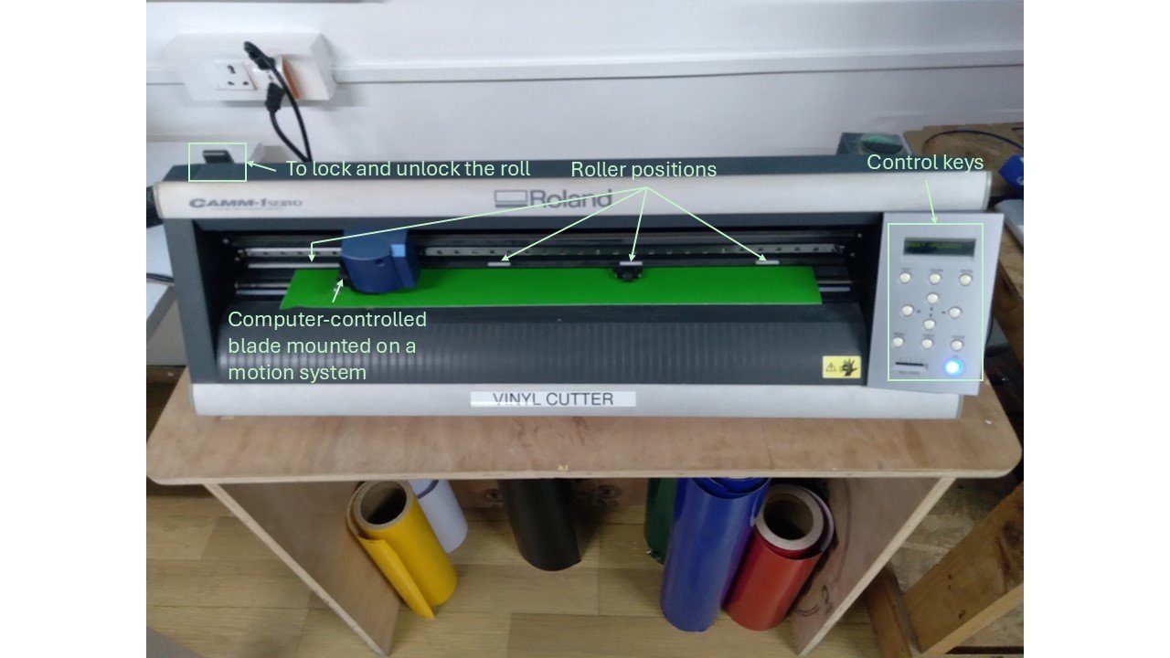
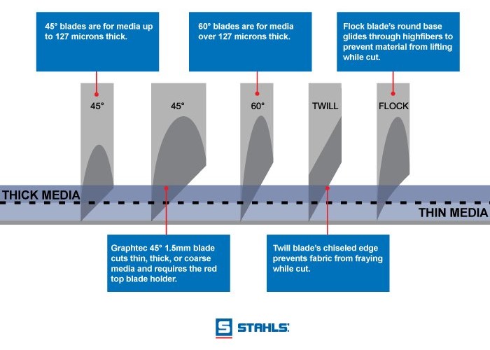
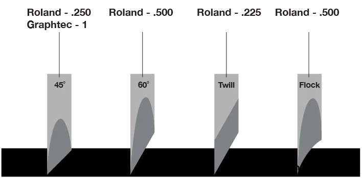
Blade selection: depends on the material vinyl or copper film, thickness of the film.
Designing files for Vinyl Cutter
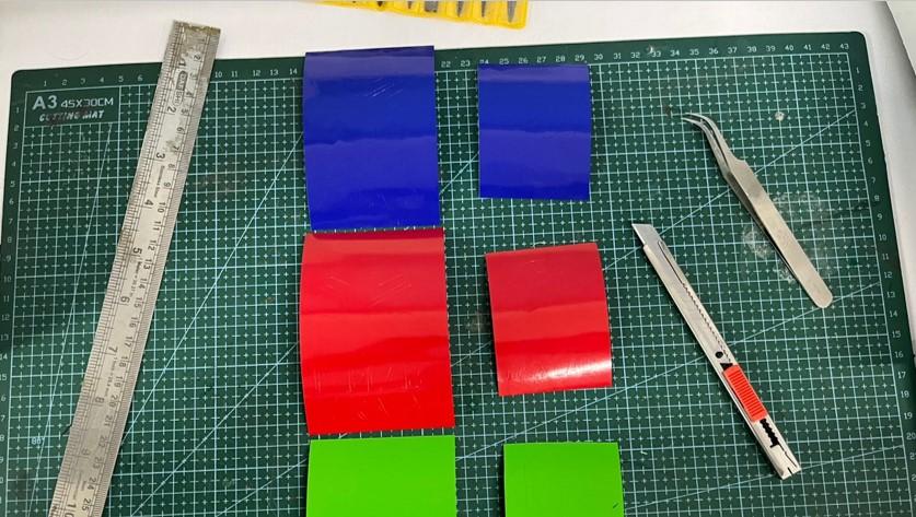
I planned to cut the FAB Academy logo and Super FabLab Kerala logo and paste it on my laptop or mobile cover. I used INKSCAPE to make SVG file of logo and then transferred the file to local desktop computer which is connected to Roland CAMM-1, this computer has a program Modsproject which runs on linux and which is used to feed or send the file to Roland CAMM-1.
First, I created three separate SVG files, since the Fab Academy logo contains three different colors, each requiring a separate vinyl cut. I downloaded the logo in PNG format and used Trace Bitmap (Shift + Alt + B) in Inkscape to convert the raster image into a vector file. After converting, I scaled each logo to 5 cm × 5 cm and arranged them side by side.
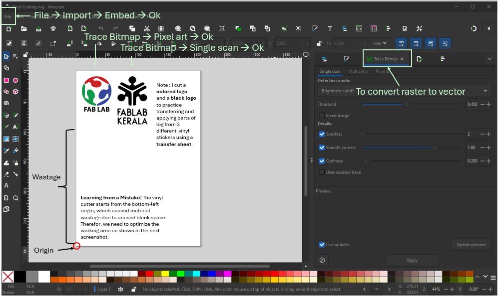
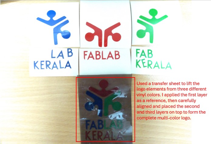
I experimented with a multi-color logo to practice vinyl cutting workflows. This helped me learn how to align multiple vinyl layers, transfer the designs using a transfer sheet, and apply them neatly onto my laptop surface.
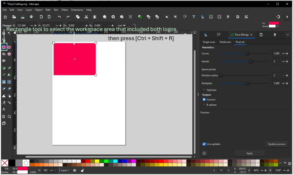
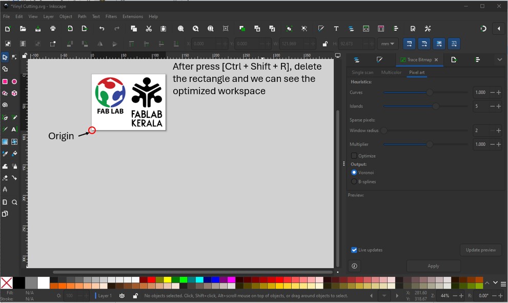
Learning from a Mistake: When sending this SVG file first time to the Roland vinyl cutter, it resulted in wasted vinyl material because the machine takes the bottom-left corner as the origin and cuts from bottom to top. This caused the unused blank area in between to be processed unnecessarily. To avoid material wastage, the design needs to be repositioned and optimized within the working area using [Ctrl+Shift+R], as shown in the next screenshot. Then save the files in SVG format.
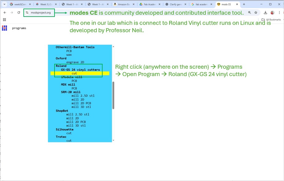
Mods CE is a modular cross platform tool for fablabs. It is based on independent but interrelated modules. mods could potentially be used for CAD, CAM, machine control, automation, building UI, read input devices, react to physical models, and much more.(mods CE)
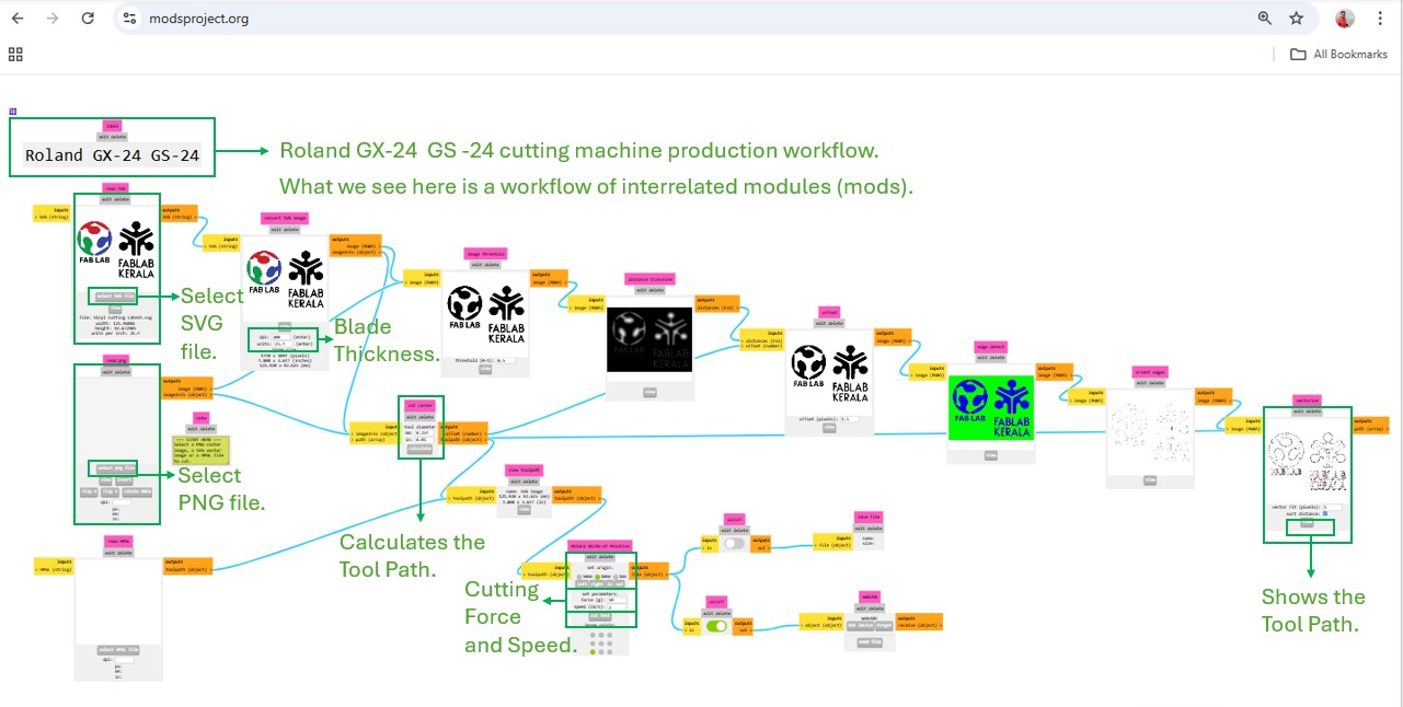
Next, we used mods CE to prepare the design for production on the Roland vinyl cutter. As shown in the images below, the SVG or PNG file is loaded into Mods by selecting the SVG file or PNG file module. After importing the file, the Calculate module is used to generate the toolpath, which converts the image into Vectors [cutting instructions for the machine].
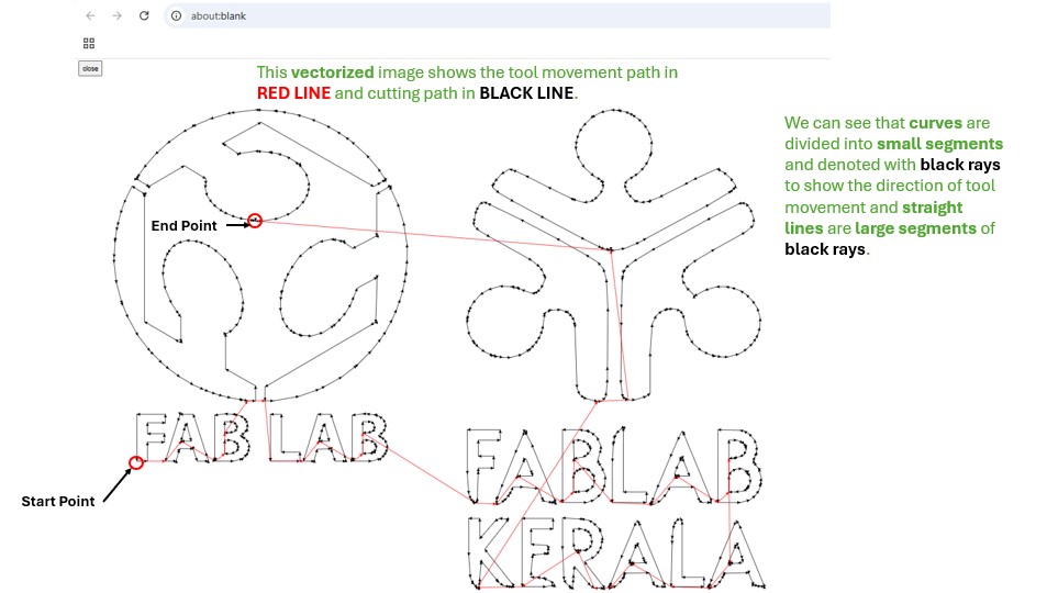
The vectorized preview displays the tool movement path in red and the cutting path in black. Curved shapes are broken into many small segments, shown as short black rays that indicate the direction of the blade’s movement, while straight lines appear as longer continuous segments. After reviewing and verifying this toolpath, the cutting instructions are ready to send to the Roland machine to begin the vinyl cutting process.
Before starting the cutting process, it is important to properly load the vinyl sheet into the machine. Release the roller pressure using the locking knob, place the vinyl roll or sheet in position, and lock it back securely. Always reset the machine before loading or unloading material so the tool head returns to the home position. Next, select the sheet type on the machine panel (Roll, Piece, or Edge) and press Enter. The cutter head will move to the left and automatically measure the width and length of the vinyl. After positioning the starting point, long-press the ORIGIN button to set the cutting origin. Before running the final job, always perform a test cut to ensure the vinyl is being cut cleanly and can be peeled easily. This helps in properly calibrating the cutting force and speed for the material being used. There are two parameters which need to be adjusted while we cut vinyl according to the material specifications.
- Force
- Speed
Now we can send the cutting instructions from mods CE to the Roland machine to begin the vinyl cutting process.
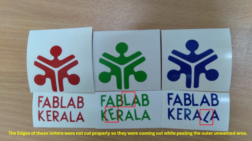
First, I carefully peeled away the unwanted surrounding vinyl. If any part of the logo lifted along with the excess material, it indicated that the cutting force or speed was not properly calibrated, and a test cut was required to adjust the settings.
I used a cooling film (also known as sun control film or window tint) as a transfer sheet to lift and align the logo from three different vinyl stickers.
After removing the outer area, I used a transfer sheet to lift the logo elements from three different vinyl colors. I applied the first layer as a reference, then carefully aligned and placed the second and third layers on top to form the complete multi-color logo.
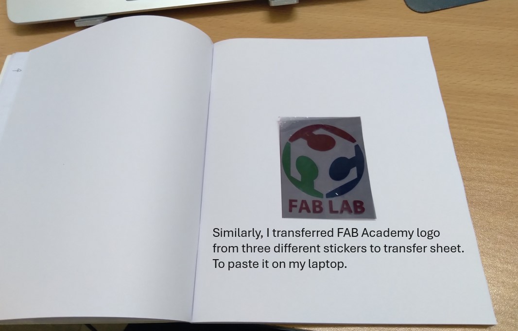
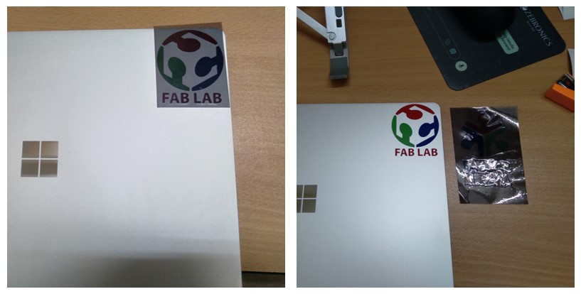
First sticker on my laptop Fab LAB looks cool!
Laser Cutting Machine [Overview]
A laser cutter is a computer-controlled (CNC) machine that uses a high-power focused laser beam to:
- Cut materials
- Engrave designs
The laser melts, burns, or vaporizes material with high precision. First designs are created in vector software (SVG, DXF, AI, and PDF-vector), then files are sent to laser machine software, the laser head follows the vector path, focused beam heats material instantly, material is cut or engraved cleanly. Laser cutter are very high precision, no physical tool contact, clean edges, fast prototyping, and complex shapes possible.
Main Parts of a Laser Cutter
- Laser source – generates the laser beam (CO₂ or fiber laser)
- Mirrors & lens – guide and focus the beam to a fine point
- X–Y gantry system – moves the laser head precisely
- Bed / honeycomb table – holds the material
- Exhaust system – removes smoke and fumes
- Controller (CNC) – reads design files and controls motion
Key laser parameters
- Power (%) – strength of the laser
- Speed – how fast the head moves
- PPI/Hz – pulse density (for engraving)
(More power + slower speed = deeper cut)
Common Material for Laser Cutting are Cardboard, Plywood, MDF, Acrylic, Leather, and Fabric. We should not cut PVC (dangerous fumes!) and Vinyl (chlorine gas) with a laser cutter.
Safety Basics
- Never cut PVC or unknown plastics
- Keep lid closed during operation
- Ensure exhaust is ON
- Never leave machine unattended
- Watch for flame on wood/acrylic
G-code vs Laser Path
Some lasers like diode lasers use G-code whereas most CO2 laser cutters use laser path.
G-code is the language used by CNC machines to move tools. It tells machine:
- Where to move (X,Y,Z)
- How fast to move
- When to turn tool ON/OFF
For example:
G1 X50 Y20 F1000-> Move to X=50mm, Y=20mm at speed 1000G1 X10 Y20-> Move tool to position (10,20)G1 Z-2-> Lower tool to cutG1 X50 Y20-> Cut straight line
Laser Path is made up of red lines, black lines and raster dots.
- Red lines → travel/movement paths
- Black lines → cutting paths
- Raster dots → engraving fills
AI prompt : Explain : G-code vs laser path explanation (Fab style)
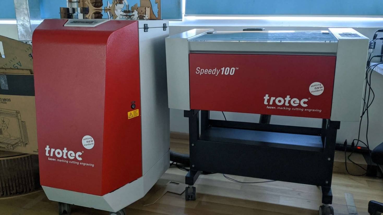
In our lab, we use a Trotec Speed 100 laser cutter.
Power–Speed Test Matrix (Very Important)
This matrix is important to find perfect cutting parameters for the material because these parameters depend on material and its thickness. This gives the best power + speed combination for the material.
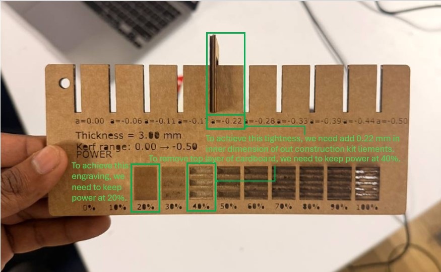
To better understand laser cutting parameters, we collaboratively designed a testing jig (fixture) as part of the group assignment and performed cutting tests on 3 mm cardboard. Our classmate Nadec Biju exceeded the expectation by developing a web-based tool that automatically generates SVG files for test jigs, which greatly streamlined the testing process. From the group assignment we find out that kerf of laser cutter for 3 mm cardboard:
What we observe is Clean edges, Full cut-through and Clear engraving.
Through this exercise, I learned the importance of parametric design in construction kit development. Since such kits often consist of dozens or even hundreds of identical interlocking parts, and may be fabricated from materials of varying thicknesses, defining material thickness and kerf as adjustable parameters is essential. By updating these values in the CAD model, all components automatically adapt, ensuring accurate fits for the given material and its thickness. This approach makes the design highly scalable, precise, and efficient.
Parametric Construction Kit
Based on the data collected during the group assignment, I began designing my own press-fit construction kit in Autodesk Fusion 360. I first defined the kerf and material compression values obtained from testing 3 mm cardboard as parametric variables.
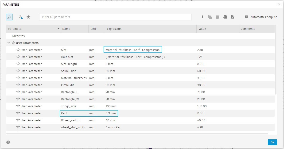
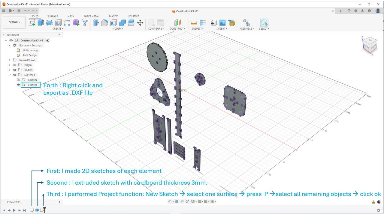
Using these parameters, I started creating various geometric components. As the design evolved, I logically identified and assigned additional key dimensions as parameters. This approach allows future adjustments to be made directly in the parameter table rather than modifying individual sketches, making the entire kit scalable and adaptable to different materials and thicknesses. In Fusion, first, I created 2D sketches for each individual element. Second, I extruded the sketches using the 3 mm cardboard thickness. Third, I used the Project function by creating a new sketch, selecting the target surface, pressing P, projecting all required edges, and confirming the operation. Finally, I right-clicked the sketch and exported it as a .DXF file for laser cutting.
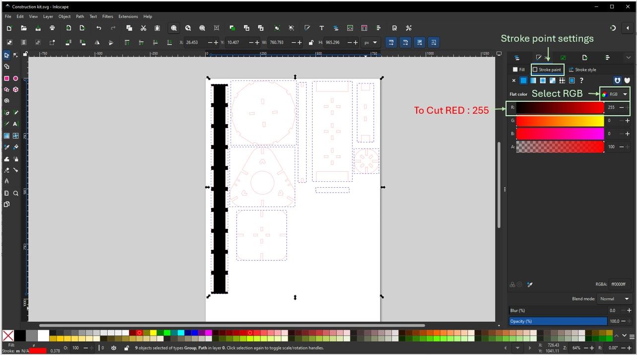
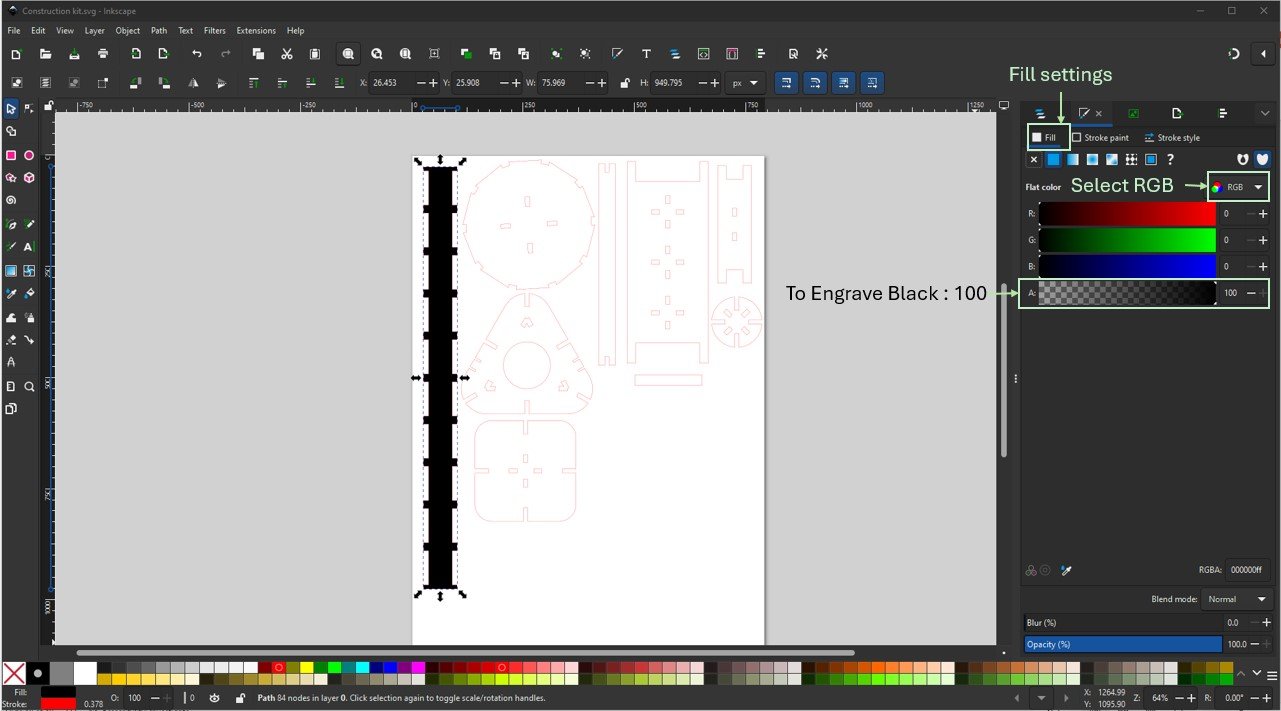
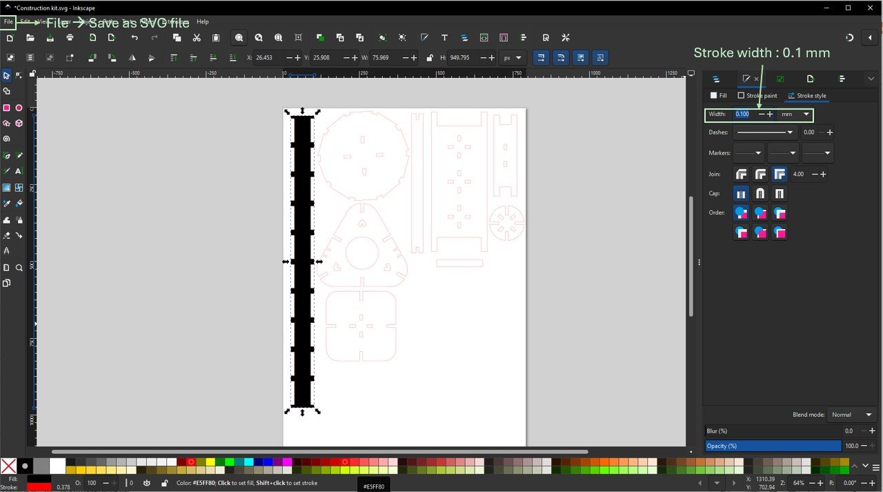
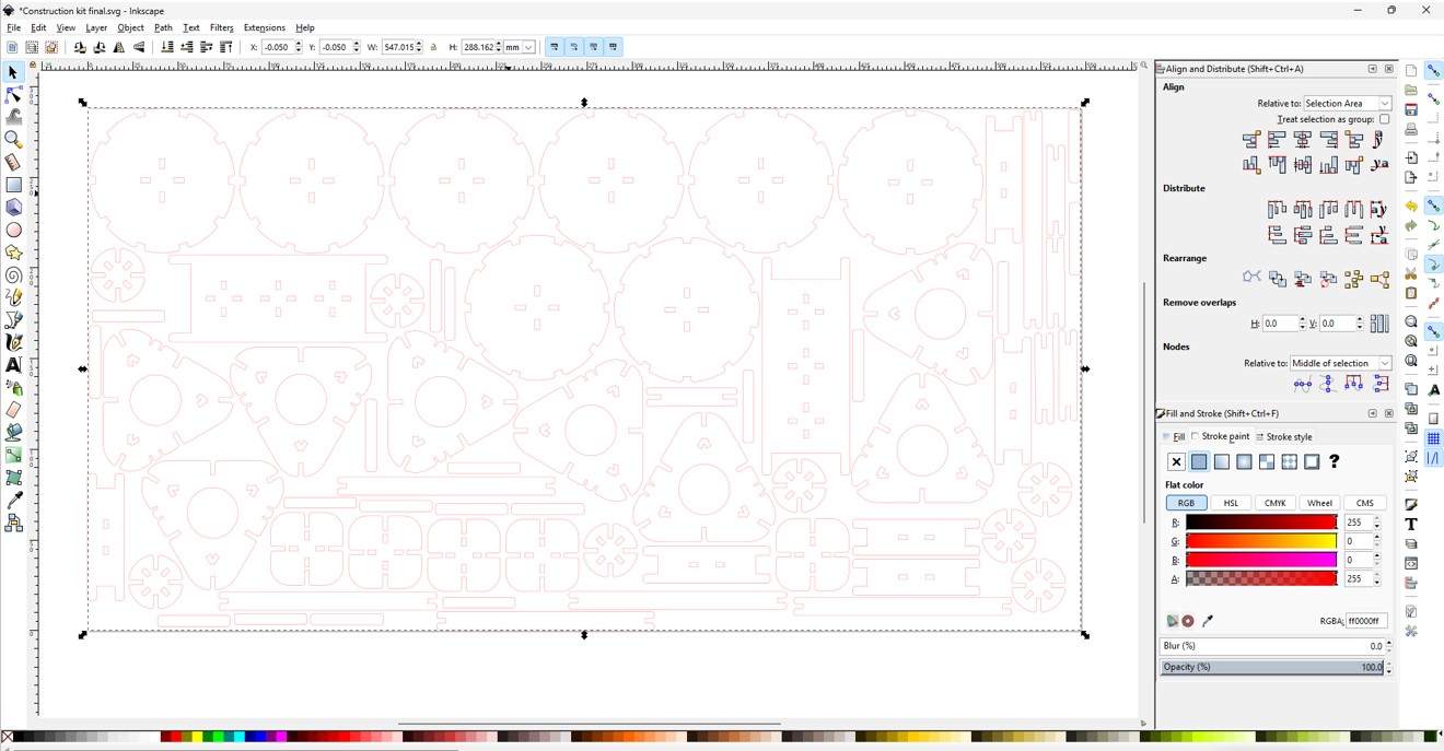
Next, I opened the DXF file in Inkscape, ungrouped the elements, and rearranged them to optimize material usage. After repositioning, I regrouped the design and set the stroke width to 0.1 mm. For engraving, I applied a black fill, and for cutting, I set the stroke color to red, as shown in the images below. Finally, I saved the file as an SVG for laser cutting.
Next, I transferred the prepared files to the local workstation connected to the Trotec Speedy 100 laser cutter. From there, the designs were set up for laser processing.
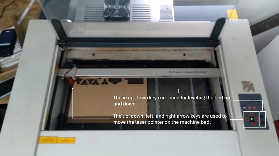
The video below demonstrates how to precisely set the laser focus on the cutting material. The work bed is slowly raised until the focus distance gauge drops, indicating the exact focal point where the laser beam is properly focused for accurate cutting.
The up, down, left, and right arrow keys are used to move the laser pointer on the machine bed. As the pointer moves, the reference position in the Trotec Job Control software also updates accordingly. This helps in precisely setting the starting point of the cut on the cardboard sheet.
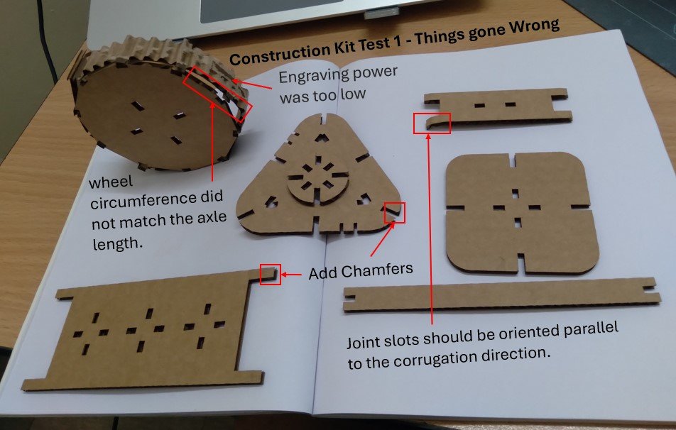
Construction Kit Test 1 – What Worked & What Needs Improvement
Areas for Improvement (to address in Test 2)
- The wheel circumference did not match the axle length, causing alignment issues
- Engraving power was too low and needs to be increased for better visibility
- Chamfers should be added to improve ease of insertion
- Joint slots should be oriented parallel to the cardboard fluting (corrugation direction) for better strength and fit
What Worked Well
- The fit tightness was excellent, confirming that the kerf and compression values are correct
- The parametric model performed as intended, allowing quick adjustments of kerf values and achieving optimal fit in Test 1
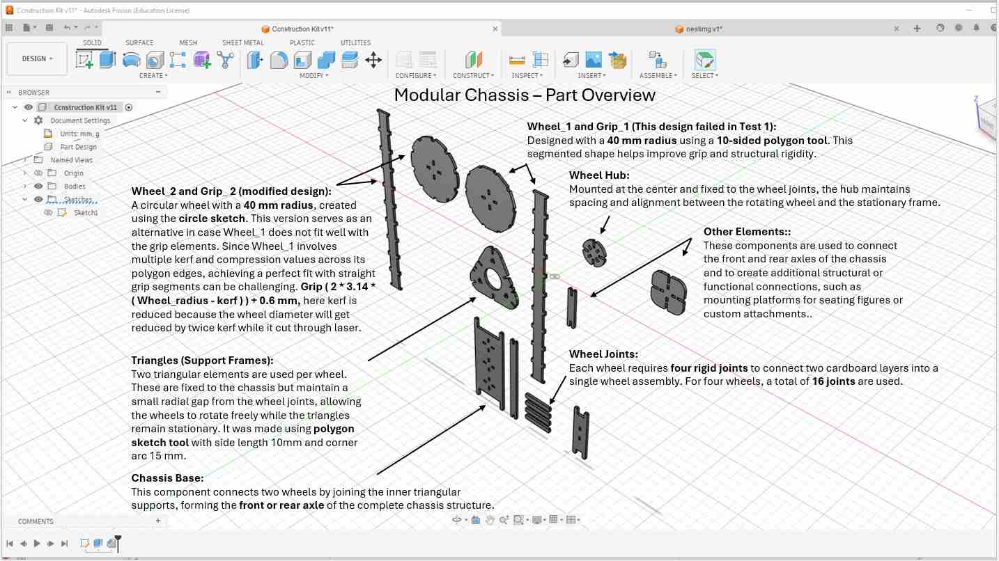
Based on the learnings from the initial tests, I redesigned the construction kit and clearly defined each component along with the tools and techniques used to create them.
I then followed the same workflow described earlier: projecting sketches in Fusion 360, exporting them as DXF files, importing them into Inkscape, and setting the appropriate fill and stroke values for laser cutting.
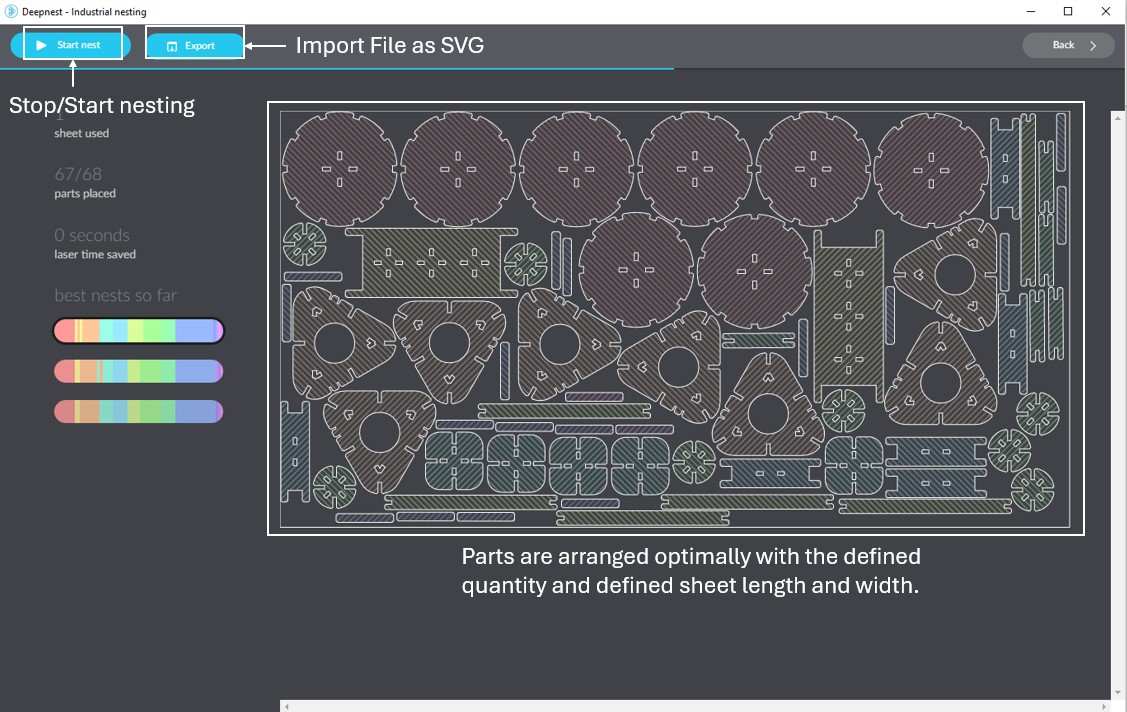
For efficient mass layout, I used the open-source nesting tool Deepnest. This automatically arranged the kit elements to optimize the cardboard sheet area and significantly reduce material waste.
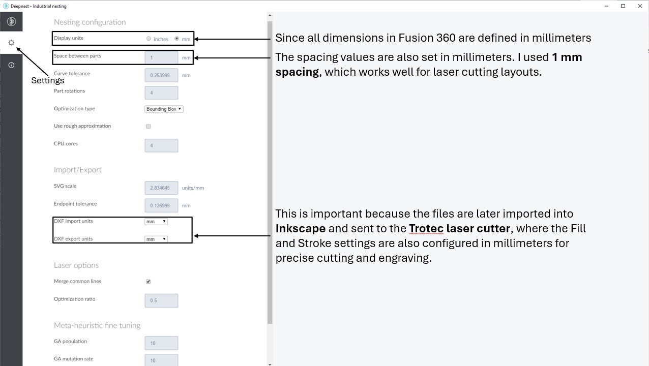
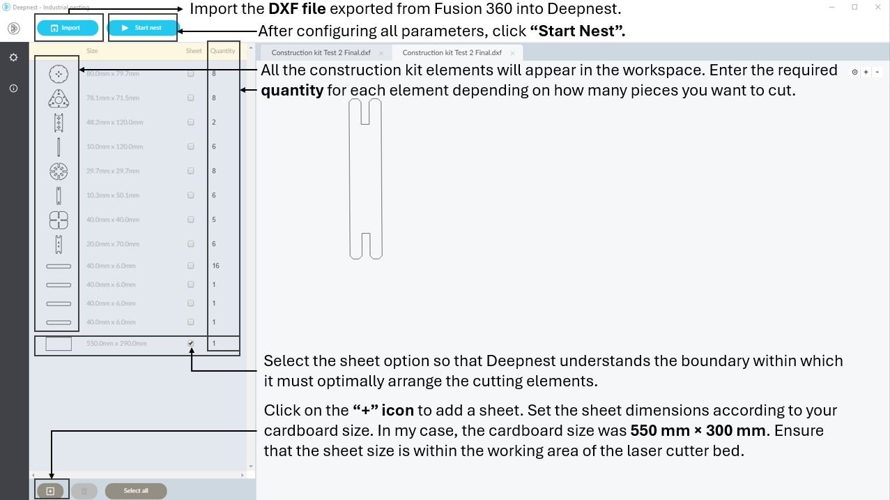
Import the DXF file exported from Fusion 360 into Deepnest. All the construction kit elements will appear in the workspace. Enter the required quantity for each element depending on how many pieces you want to cut. Click on the “+” icon to add a sheet. Set the sheet dimensions according to your cardboard size. In my case, the cardboard size was 550 mm × 300 mm. Ensure that the sheet size is within the working area of the laser cutter bed. Select the sheet option so that Deepnest understands the boundary within which it must optimally arrange the cutting elements. After configuring all parameters, click “Start Nest” to automatically optimize the layout and minimize material waste.
Once the parts are arranged optimally, stop the nesting process and click Import, then save the layout as an SVG file. This SVG can now be opened in Inkscape to verify and adjust the Fill and Stroke settings for laser cutting.
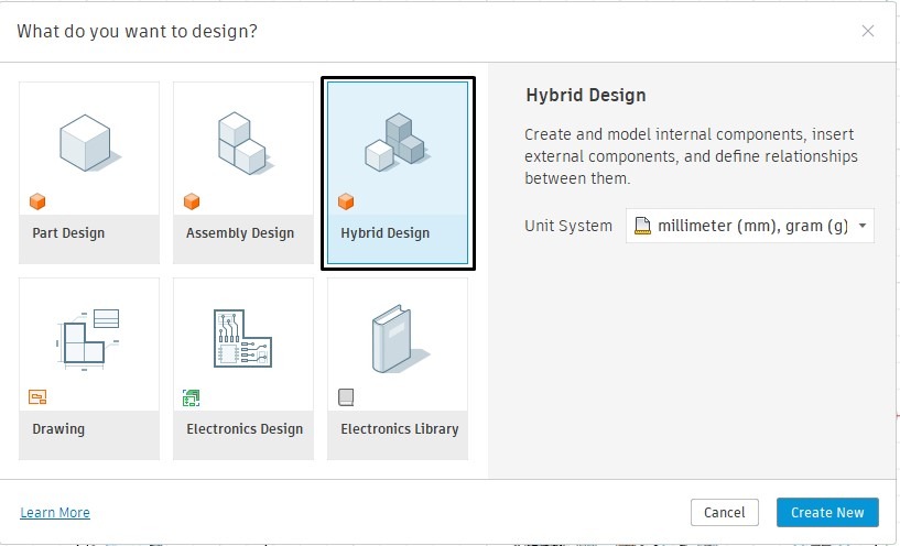
Note: This nesting process can also be done directly in Fusion 360 using the Arrange function. However, since my construction kit was designed within a single part file, Fusion treated all elements as one component, which prevented the Arrange tool from working properly. In future designs, I will use a hybrid or multi-component approach to enable nesting directly within Fusion 360.
Next, I transferred the SVG file to the local desktop computer connected to the Trotec laser cutter using the Send Anywhere file-sharing tool. I opened the file again in Inkscape to double-check the laser settings:
- Black fill for areas to be engraved
- Red (RGB 255,0,0) stroke for cutting paths
- Stroke width: 0.1 mm
Once everything was verified, I pressed Ctrl + P to print. The Trotec laser cutter appeared in the printer list, which automatically opened the Trotec JobControl software to begin the cutting process.
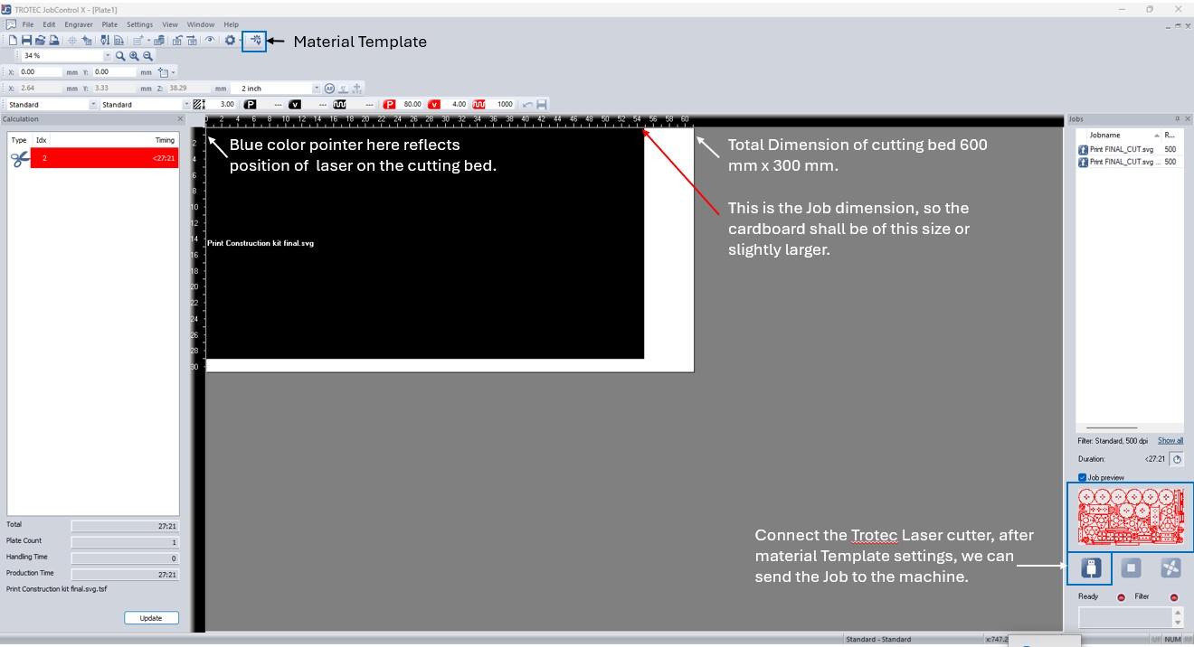
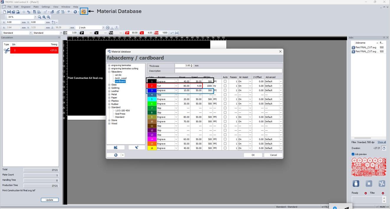
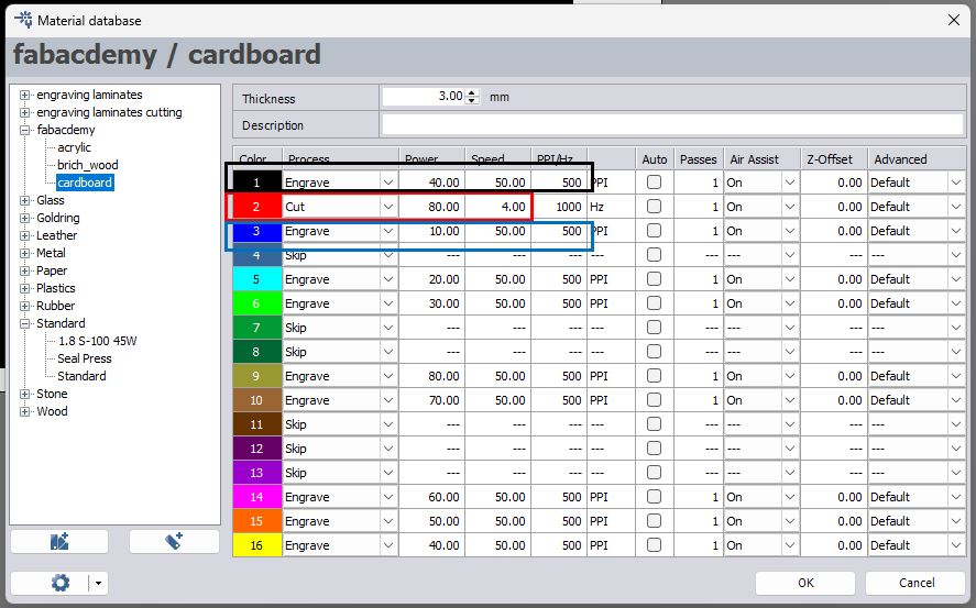
As shown in the image below, different colors are assigned to different laser operations such as cutting and engraving. The red color represents cutting, so in Inkscape I set all cut lines to red. In Trotec JobControl, the cutting parameters were set to speed 4 and power 80, based on the optimal values obtained from our group test jig.
The black color was assigned for engraving at 40% power, while blue was used for light engraving at 10% power, producing different surface effects. As observed in the test jig, 40% power removed the top layer of cardboard clearly, whereas 10% power produced a very subtle mark.
These parameter settings can be saved in the Trotec material database, making it easy to reuse accurate cutting and engraving profiles for future jobs.
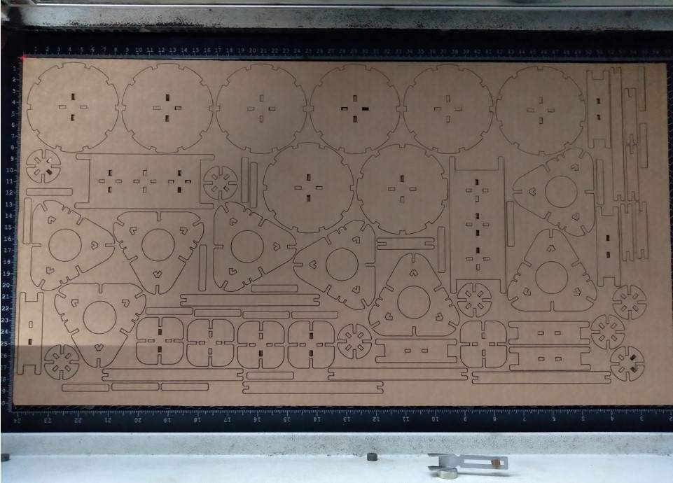
Once we sent the file to machine, the laser cutter then began the cutting process.
Below is the final output after the laser cutting was completed. I used one pass of the laser however a few elements we not cut properly from the bottom layer of the cardboard for which I need to use cutter to remove it carefully.
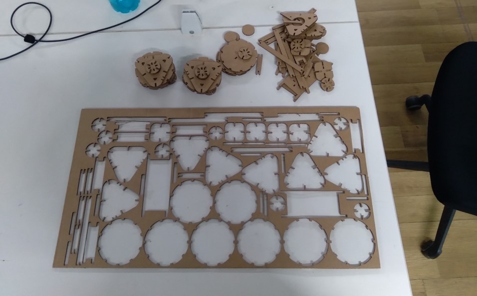
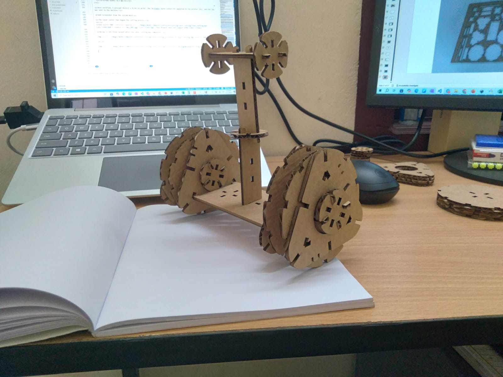
After cutting, I began assembling the construction kit elements. Since the chassis was designed in a modular form, I first assembled the wheels and then explored multiple ways of connecting them using the other chassis components.
The first structure I successfully built was a two-wheel Segway-style vehicle.
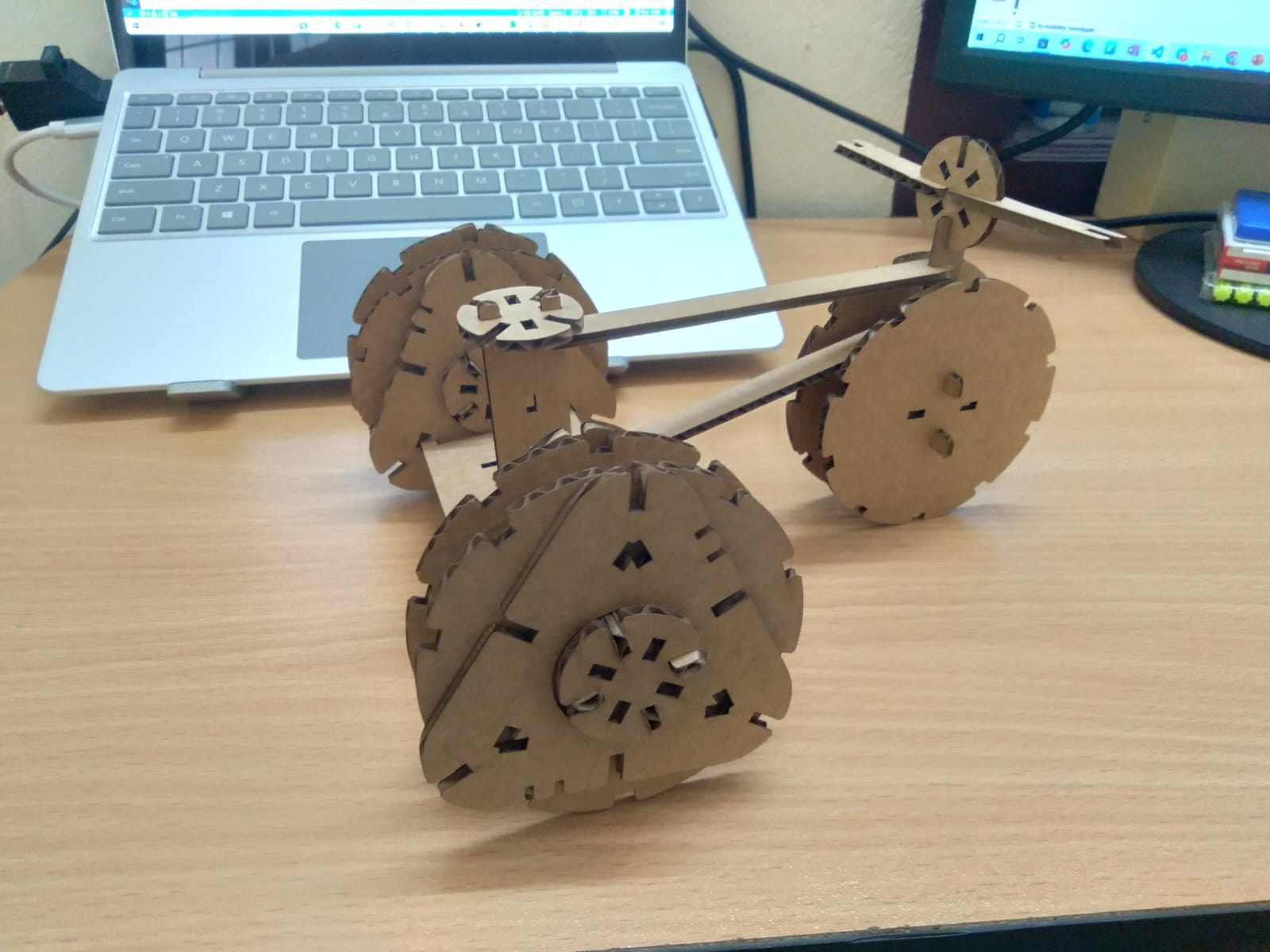
Next, I assembled a three-wheel tricycle configuration, demonstrating the flexibility of the modular design.
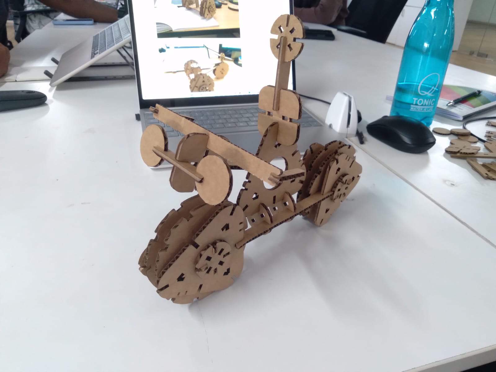
Finally, I assembled a bike with a rider figure from the modular elements.