Week 9 — Input devices
Group assignment for this week is on the Chaihuo Week 9 group assignment page. The rest of this page is my individual work.
Individual assignment
I read a rotary encoder on the milled board from
Week 6 and
Week 8. The input device is a
KY-040 module, driven by pcb_testing on the
W9 INPUT page.
Assembled circuit
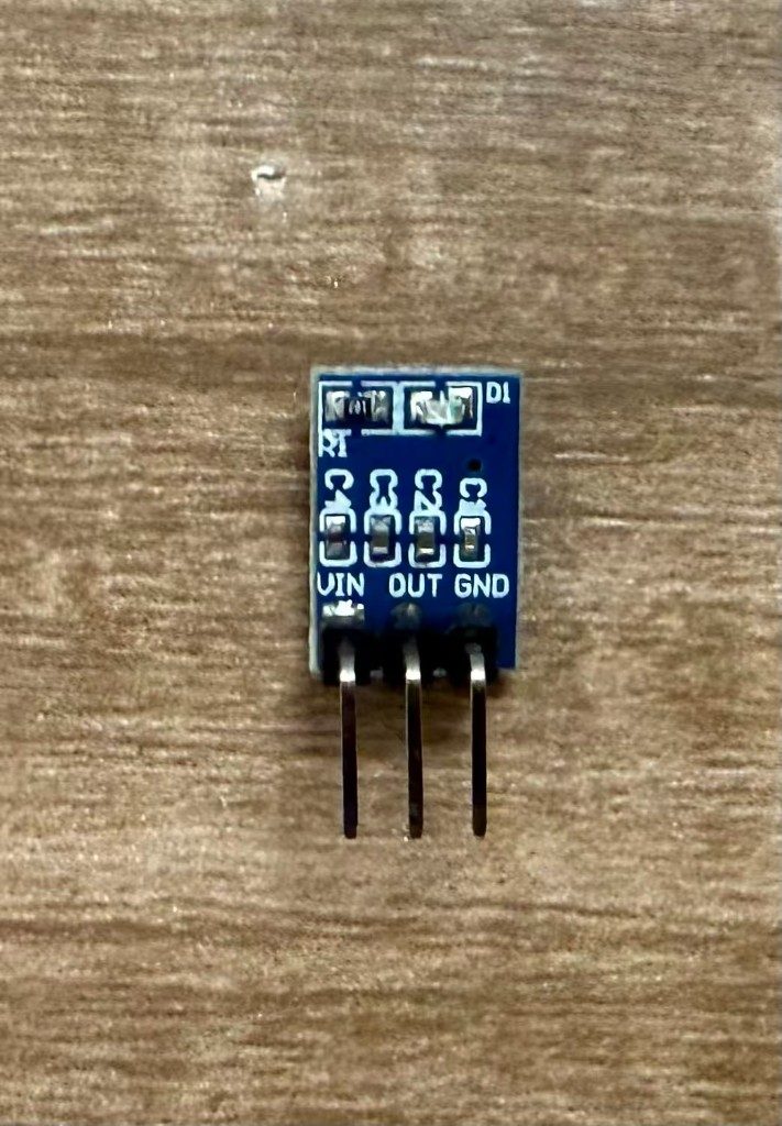
The encoder connects to the XIAO carrier over jumper wires, with an AMS1117 branch for 3.3 V power after the on-board rail was damaged during soldering.
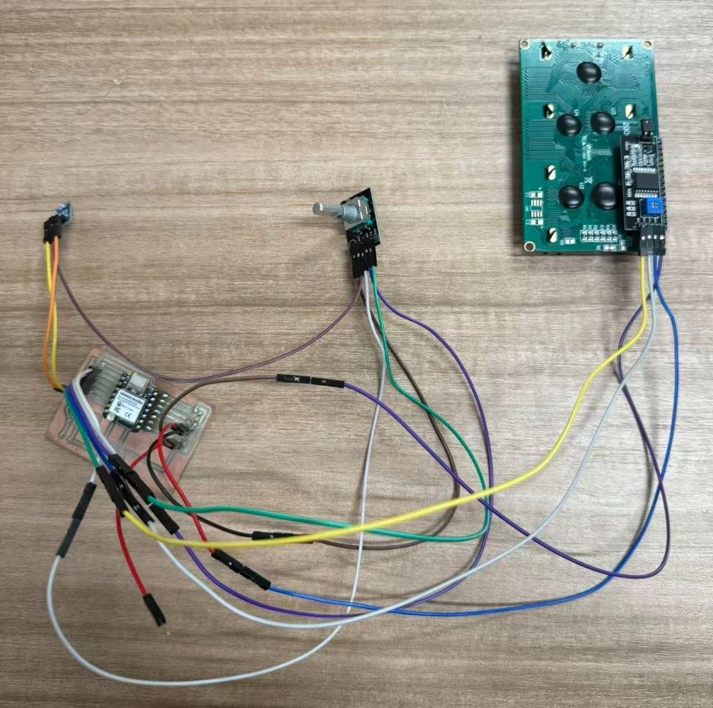
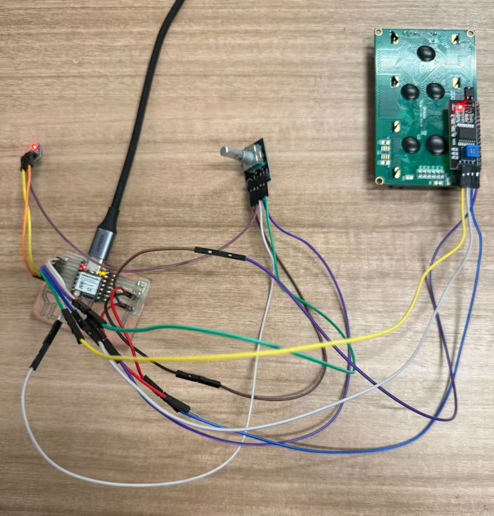
Wiring
Pin assignments come straight from pcb_testing.ino. The XIAO is powered over
USB-C; encoder signals go to D1–D3. Because the on-board 3.3 V
pad was damaged in Week 8, the encoder’s + pin is fed from a separate
AMS1117 branch — not from a GPIO.
KY-040 → XIAO (signals)
| KY-040 pin | XIAO pin | In code |
|---|---|---|
| SW | D1 |
PIN_SW — long press (2 s) switches mode |
| DT | D2 |
PIN_DT |
| CLK | D3 |
PIN_CLK |
| GND | GND | Common ground with XIAO and AMS1117 |
AMS1117 → KY-040 (power only)
The regulator exists because the PCB 3.3 V trace was lifted during soldering. Feeding the encoder from raw 5 V would also pull CLK/DT/SW highs to ~5 V and overstress the XIAO GPIOs.
| AMS1117 pin | Connects to | Notes |
|---|---|---|
| VIN | 5 V (USB / bench) | Bench 5 V rail |
| OUT | KY-040 + |
Regulated 3.3 V — encoder outputs stay within MCU logic levels |
| GND | Common GND | Tied to XIAO GND and encoder GND |
Learning the KY-040 rotary encoder
Before wiring I looked up how an incremental encoder behaves on GPIO. The module exposes
quadrature signals CLK and DT plus a push switch SW.
I used:
- Wokwi KY-040 reference for CLK/DT timing, internal pull-ups, and quadrature direction.
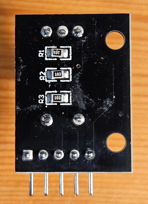
- The open-source KY040 Arduino library (module photos below) for pin naming and the three 10 kΩ pull-up resistors on the PCB.
-
The
Seeed XIAO ESP32-S3 wiki
to map Arduino pin names (
D1–D3) to safe 3.3 V logic levels.
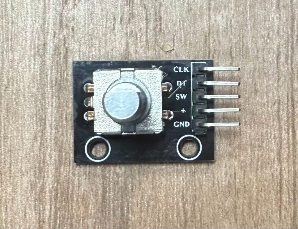
Reference module photos (front and back) from the codingABI/KY040 library — the rear side shows R1–R3, the 10 kΩ pull-ups that tie CLK, DT, and SW to VCC. That is why powering the module at 5 V can produce 5 V-high outputs even when the MCU is 3.3 V.

Power workaround: AMS1117 3.3 V module
During assembly I accidentally damaged the on-board 3.3 V trace (Week 8). With that rail unusable I powered the bench from 5 V, but the KY-040 module is often sold as a 5 V–tolerant board whose output highs can reach ~5 V on CLK/DT. The XIAO ESP32-S3 GPIOs are 3.3 V only and are not 5 V tolerant, so feeding 5 V encoder outputs directly would risk damaging the MCU.
The fix was an external AMS1117 3.3 V step-down module: 5 V in, regulated
3.3 V out to the encoder’s + pin only. CLK, DT, and SW still connect to the
XIAO inputs, but now swing within 3.3 V logic levels. Common ground ties the regulator,
encoder, and board together. The IC itself is an
AMS1117 fixed 3.3 V LDO
(Advanced Monolithic Systems); the blue breakout board adds input/output capacitors and a
power LED around that three-pin regulator.
How the firmware reads the encoder
Sketch pcb_testing.ino polls CLK and DT on every loop
pass. When CLK changes state, the firmware compares it to DT to decide
direction (+1 or −1) and updates an encoderSteps counter. On the
W9 INPUT page the LCD prints the live CLK/DT/SW levels and that step count;
serial logs mirror the same fields every 500 ms. The shaft switch uses a 35 ms debounce;
a two-second hold cycles through sketch pages (W8 → W9 → W10 → W11).
W9 INPUT: live encoder readout
Hold the encoder switch for two seconds to step through sketch pages until the LCD shows W9 INPUT. The second line then tracks the KY-040 in real time:
C— CLK, quadrature clock line (0 or 1)D— DT, quadrature data line (0 or 1)S— SW, the shaft push switch (UPorDN)d— cumulative step count from rotation; increases or decreases with direction and can go negative
Rotating the knob toggles C/D and steps d; pressing
the shaft flips S. The clip below shows those fields updating on the LCD
(audio removed).
Download Arduino sketch (pcb_testing.ino)
Reflection
Less about finding the perfect sensor than making a damaged production board still teach something. The AMS1117 workaround turned a soldering mistake into a clear lesson on level shifting; the encoder is simple on paper and harder on a hand-wired milled board.
The group probing session helped interpret what showed up on the LCD: quadrature as two time-offset square waves, and a logic analyzer catching missed edges that serial prints hide. I did not need an LA on my own bench to pass, but knowing what clean CLK/DT transitions look like helped when counts jumped on a loose jumper.