Week 16 - System Integration
Individual assignment
This week was about turning separate tests into one object. My final project, Brain Fog Insight Companion, has a desktop host and a wearable band. Before this week I had working pieces on breadboards: screen, speaker, microphone, camera, local eye-state model, BLE band, cloud voice, and 40 Hz audio. The system integration job was to decide where each part lives, how power and data move, and how to make the prototype look like one finished device instead of a pile of modules.
The project is a wellness and behavior-support prototype. It is not a medical diagnostic device.
Integration plan
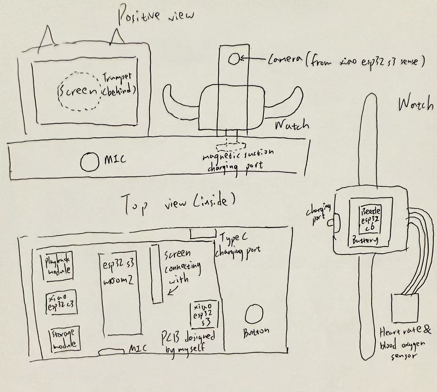
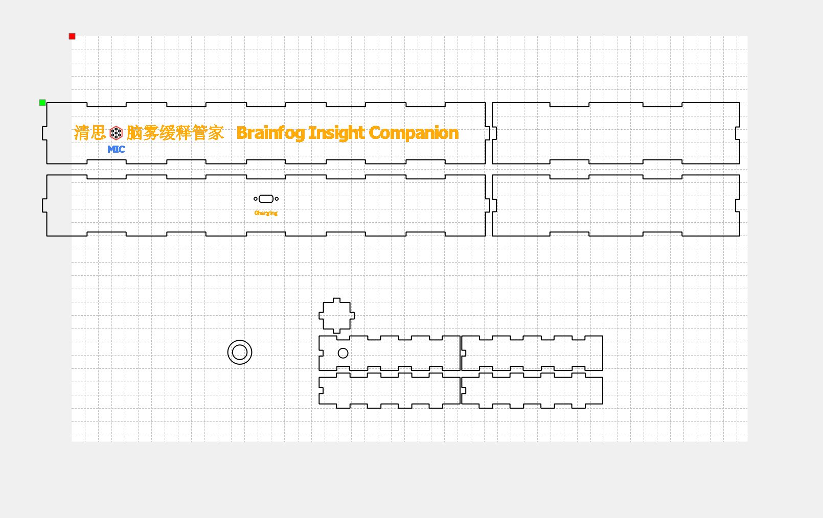
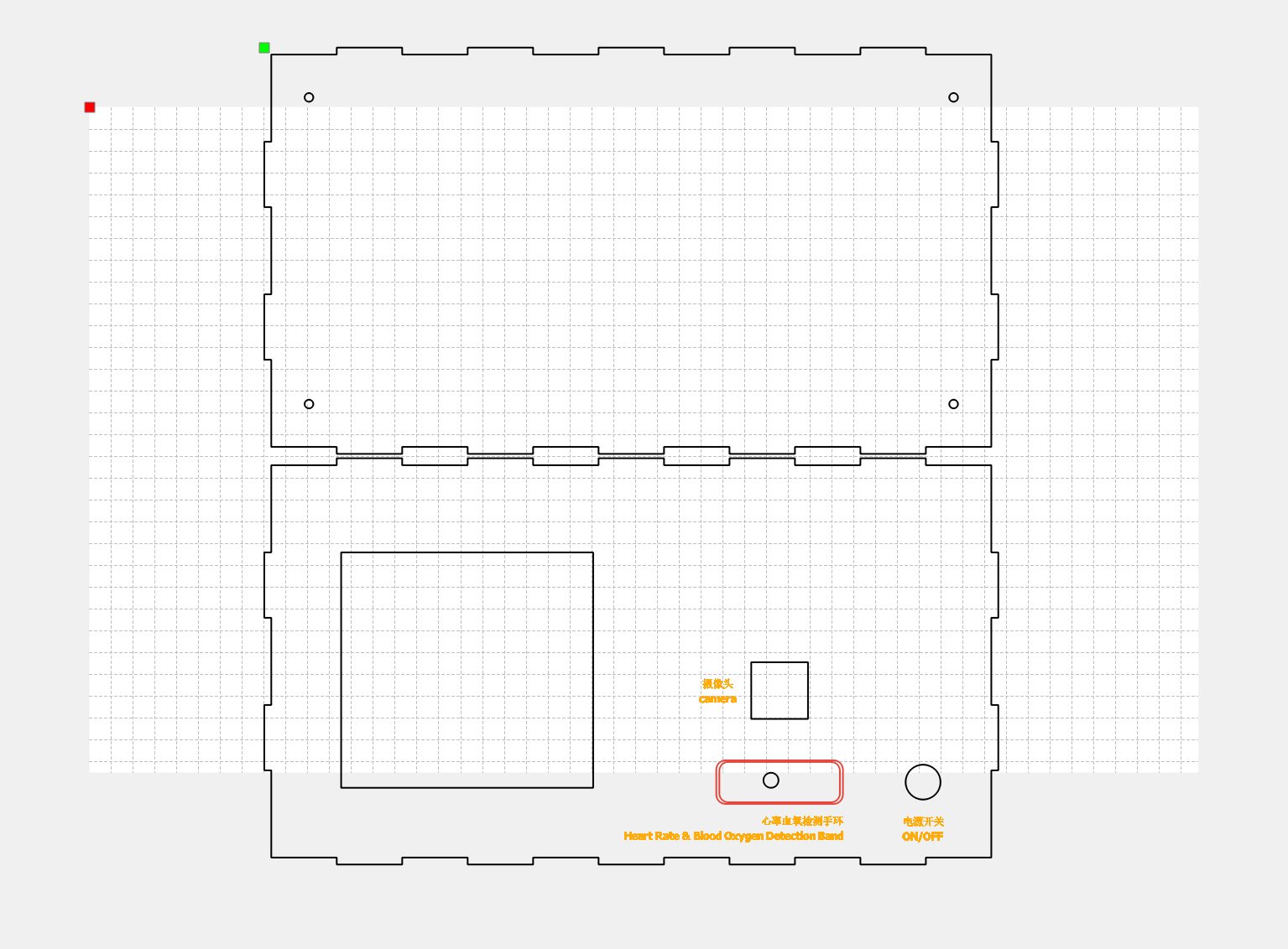
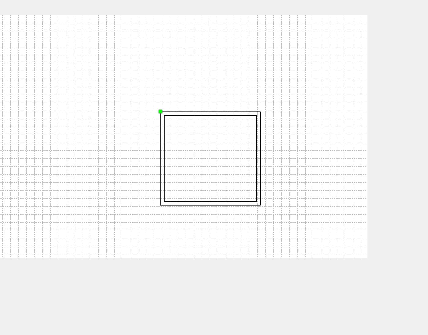
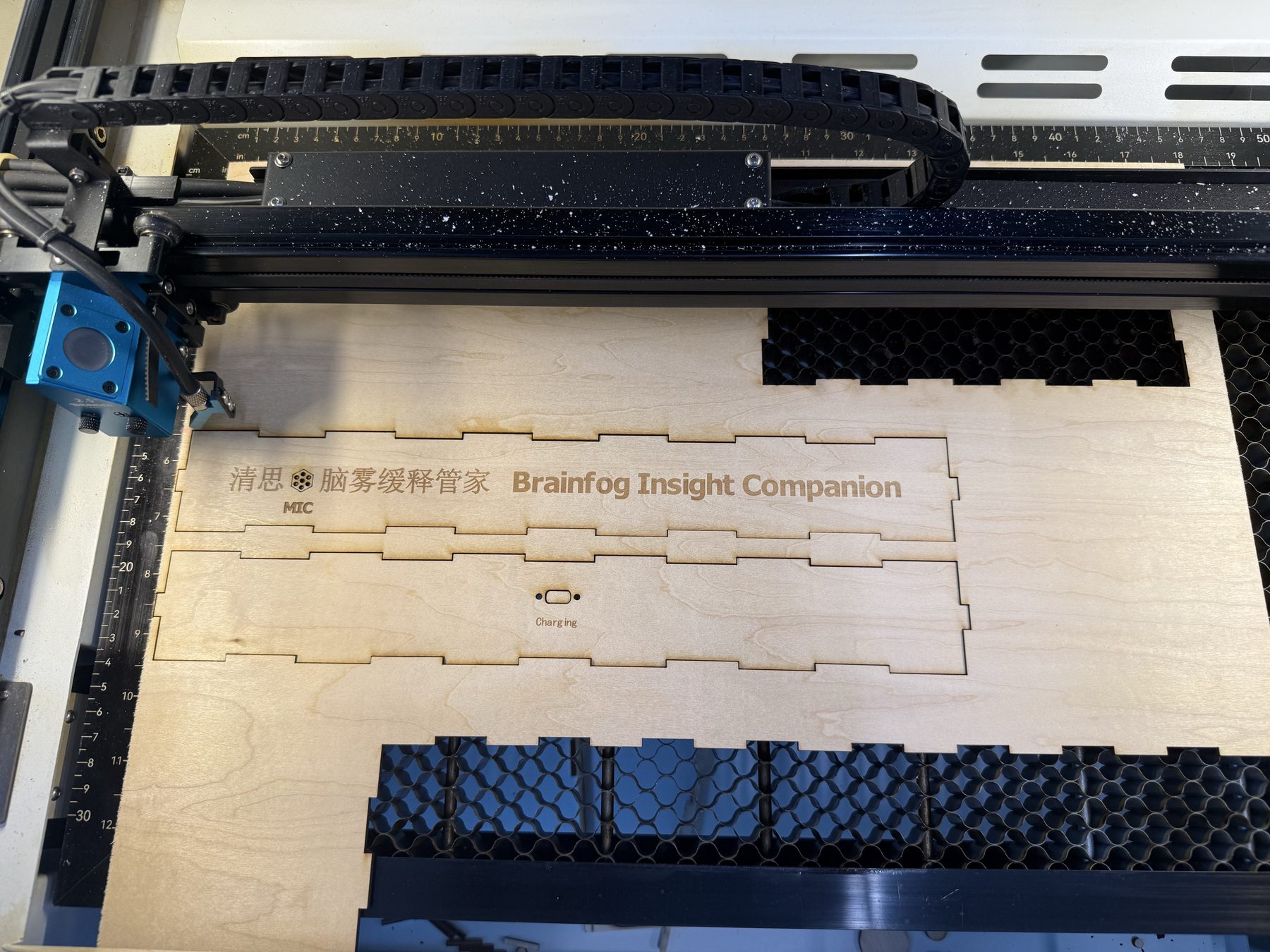
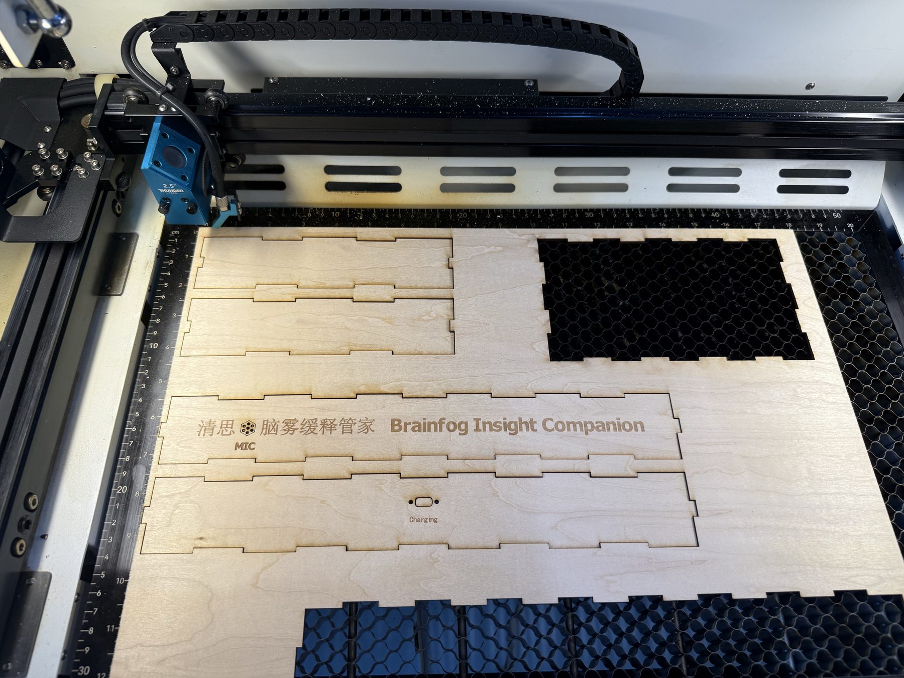
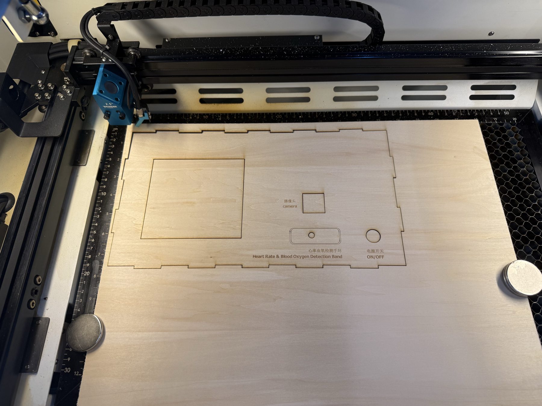
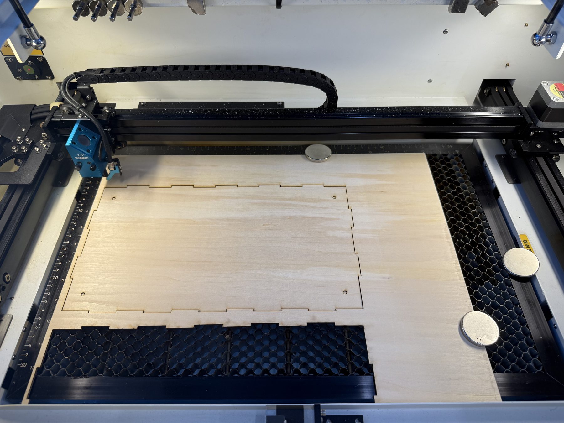
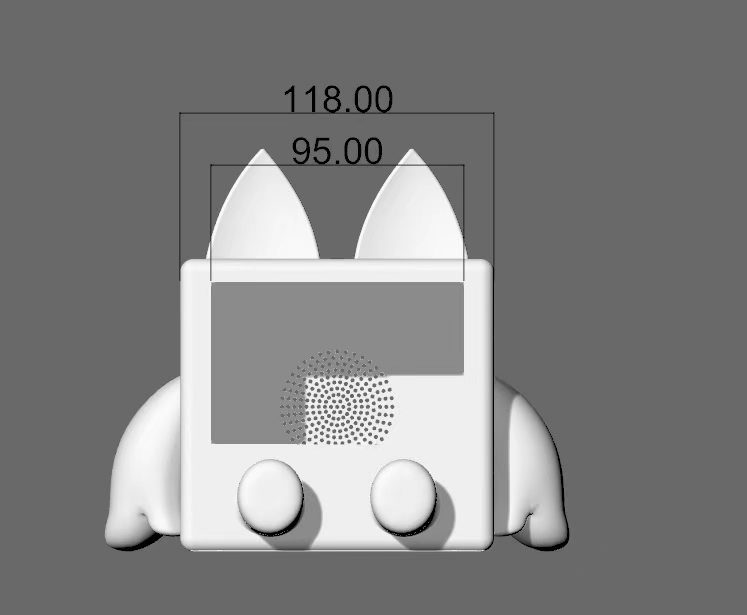
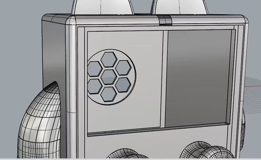
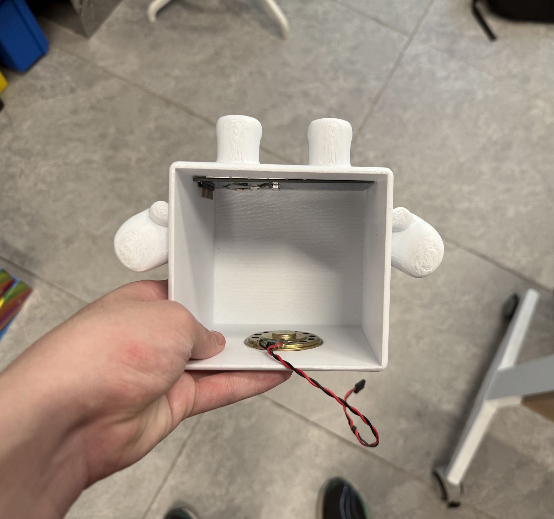
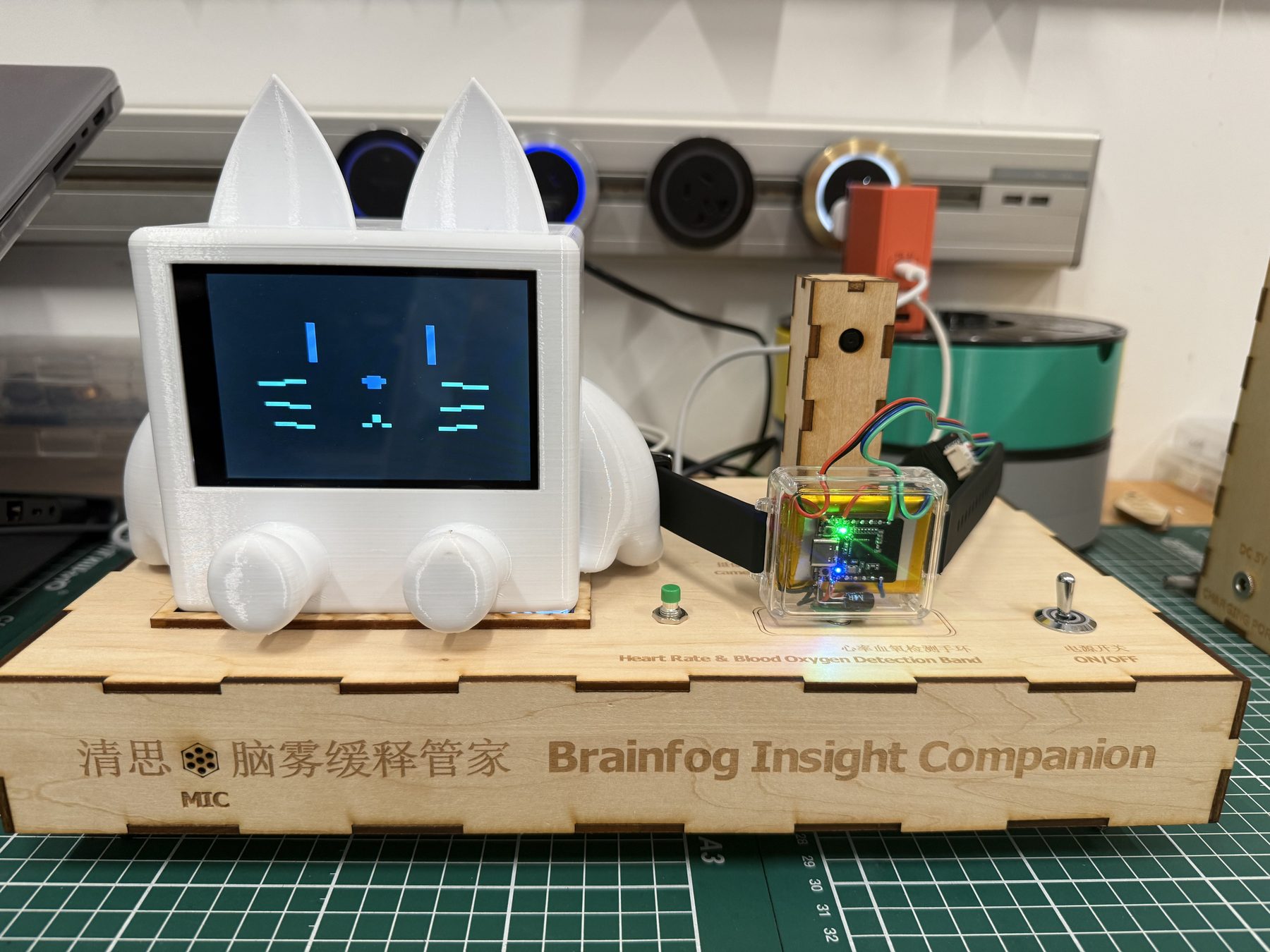
I planned the product as a laser-cut platform with electronics inside. The left side holds the 3D printed host shell, with the screen and speaker fitted into the front. The right side holds a small laser-cut tower for the camera. The front edge reserves a magnetic charging position for the wearable band. A left push button triggers proactive voice dialogue. A right master switch controls the desktop host, while the watch charging line stays available. A Type-C port on the back powers the platform.

System architecture
The final architecture uses more than one microcontroller because each board has a narrow job. That made debugging less confusing. The WROOM host does the screen, audio, voice, and main state logic. The XIAO ESP32S3 Sense runs the local eye-open / eye-closed model from its camera and reports blink state to the WROOM through GPIO. The wearable band sends heart-rate and SpO2 data over BLE. A XIAO ESP32-C3 bridge listens for those advertisements and forwards clean lines to the WROOM over UART.
| Subsystem | Connection | Why it is separate |
|---|---|---|
| Wearable band | BLE advertisement to XIAO ESP32-C3 bridge | It can stay on the wrist and send HR / SpO2 without pairing delays. |
| XIAO ESP32-C3 bridge | UART to WROOM host | The WROOM does not spend its main loop managing BLE scan details. |
| XIAO ESP32S3 Sense | Camera model output through GPIO to WROOM | Eye open / closed detection stays local and simple: the host receives state, not video. |
| WROOM host | Screen, speaker, microphone, SD card, WiFi, buttons, power switch | It owns the user-facing loop: display, voice, intervention, and logging. |
| Alibaba Bailian voice path | WiFi WebSocket from WROOM | Used for ASR, LLM reply, and TTS during voice interaction. |
End-to-end function flow
The finished prototype is meant to run as one desk device, not as separate electronics tests. A normal session starts from the rear Type-C power input. The right switch powers the desktop host, while the wearable charging position on the front can still be used. The screen boots into the host UI, the camera tower watches the user's eye state through the XIAO ESP32S3 Sense, and the wearable band sends heart-rate and SpO2 data through the C3 bridge.
During use, the WROOM combines three inputs: blink state from the XIAO S3, biometric data from the wearable, and optional voice input from the microphone. The screen shows the current state and the system can run an intervention: 40 Hz audio, a guided breathing or behavior suggestion, or a spoken response from the cloud voice path. The left button gives the user a direct way to start proactive dialogue without touching code or opening a serial monitor.
| Step | What happens | Hardware involved |
|---|---|---|
| 1. Power and wake | Rear Type-C powers the platform; the right switch turns on the desktop host. | Power input, master switch, WROOM host |
| 2. Sense | Camera classifies eye open / closed; wearable measures HR and SpO2. | XIAO ESP32S3 Sense, Beetle band, MAX30102 |
| 3. Transfer | Eye state reaches WROOM through GPIO; wearable data reaches WROOM through C3 UART. | XIAO S3 GPIO link, XIAO C3 BLE bridge |
| 4. Decide | WROOM updates the UI and decides whether the state looks normal or needs intervention. | WROOM, screen, firmware logic |
| 5. Intervene | The system can play 40 Hz audio, show guidance, or answer through voice interaction. | Screen, microphone, MAX98357A speaker path, WiFi voice service |
| 6. Re-check | The same sensors keep running so the user can compare the state before and after. | Camera, wearable, WROOM UI |
Firmware flow
The product runs four small programs at once. Each board keeps one job so the host is not doing everything in one loop.
| Board | What the program does |
|---|---|
| Beetle band | Reads the MAX30102 about once per second, then sends heart rate, SpO₂, and temperature over BLE. |
| XIAO ESP32-C3 bridge | Scans for the band, parses each packet, and forwards JSON lines plus a link-status message to the WROOM over UART. |
| XIAO ESP32S3 Sense | Runs the local eye open/closed model and reports eye state to the host. The WROOM never processes camera frames. |
| WROOM host | Owns the touch UI, 60-second measurement session, risk score, intervention playback, SD history, and cloud voice. |
On the host, a normal user session looks like this:
- Boot and home. After power-on the screen shows live vitals, band link status, and current eye state. The host keeps reading UART lines from the C3 bridge and eye-state updates from the camera board.
- Start detection. The user starts a 60-second measurement from the touch UI. During that minute the host logs one sample per second: blink rate from the eye model, plus the latest heart rate and SpO₂ from the band.
- Count blinks. The camera board only reports open, closed, or transition. The host runs a small debounce step so a single slow close does not become ten blinks. Only a full open → close → open cycle counts.
- Result page. When the minute ends, the host combines blink rate, heart rate, and SpO₂ into one rule-based Brain Fog score from 0 to 100, then maps it to Low, Mild, Moderate, or High. A short text suggestion appears on screen.
- Intervention offer. The host asks whether to run an intervention. If the user accepts, it plays about three minutes of 40 Hz audio through the speaker and flashes a green area on the screen. The user can stop early. When playback ends, a short post-intervention message plays.
- Voice on demand. The left button starts a cloud voice session at any time: microphone capture, speech recognition, Aquarius reply, then text-to-speech on the speaker. Voice and measurement can block each other so only one runs at a time.
- History and standby. Finished sessions can be stored on the SD card and reviewed later. If nothing happens for a while, the screen can dim to a sleep page until the user taps to wake it.
The score is rule-based, not a trained medical model. Blink rate carries the most weight because it is always available at the desk. Heart rate and SpO₂ adjust the score when the band is connected and the sensor has good skin contact.
WROOM wiring map
I kept a pin map while moving from breadboard to PCB. This table is the wiring used for the integrated desktop host. The C3 bridge wiring also matches the bridge firmware comments: C3 D6 is TX to WROOM GPIO39, and C3 D7 is RX from WROOM GPIO38.
| Module | Module signal | WROOM / power connection |
|---|---|---|
| Screen + SPI adapter | NT / INT | GPIO14 |
| NC | Not connected | |
| SDA | GPIO13 | |
| RST | GPIO12 | |
| SCL | GPIO11 | |
| SDO / MISO | GPIO10 | |
| LED | GPIO9 | |
| SCK | GPIO46 | |
| SDI / MOSI | GPIO3 | |
| DC | GPIO8 | |
| RESET | GPIO18 | |
| CS | GPIO17 | |
| GND | GND | |
| VCC | 3V3 | |
| INMP441 microphone | SCK | GPIO6 |
| WS | GPIO5 | |
| L/R | GND | |
| SD | GPIO1 | |
| VDD | 3V3 | |
| GND | GND | |
| XIAO ESP32S3 Sense | 3V3 | 3V3 |
| GND | GND | |
| D6 | GPIO16 | |
| D7 | GPIO15 | |
| Proactive dialogue button | Signal | GPIO7 |
| MicroSD module | VCC | 3V3 |
| GND | GND | |
| CS | GPIO2 | |
| MOSI | GPIO42 | |
| SCK | GPIO41 | |
| MISO | GPIO40 | |
| INST | Not connected | |
| XIAO ESP32-C3 bridge | D6 / TX | GPIO39 / RX |
| D7 / RX | GPIO38 / TX | |
| GND | GND | |
| 3V3 | 3V3 | |
| MAX98357A playback module | LRC | GPIO48 |
| BCLK | GPIO47 | |
| DIN | GPIO21 | |
| GAIN | Not connected | |
| SD | Not connected in firmware pin map | |
| GND | GND | |
| VIN | 5V |
Wearable wiring
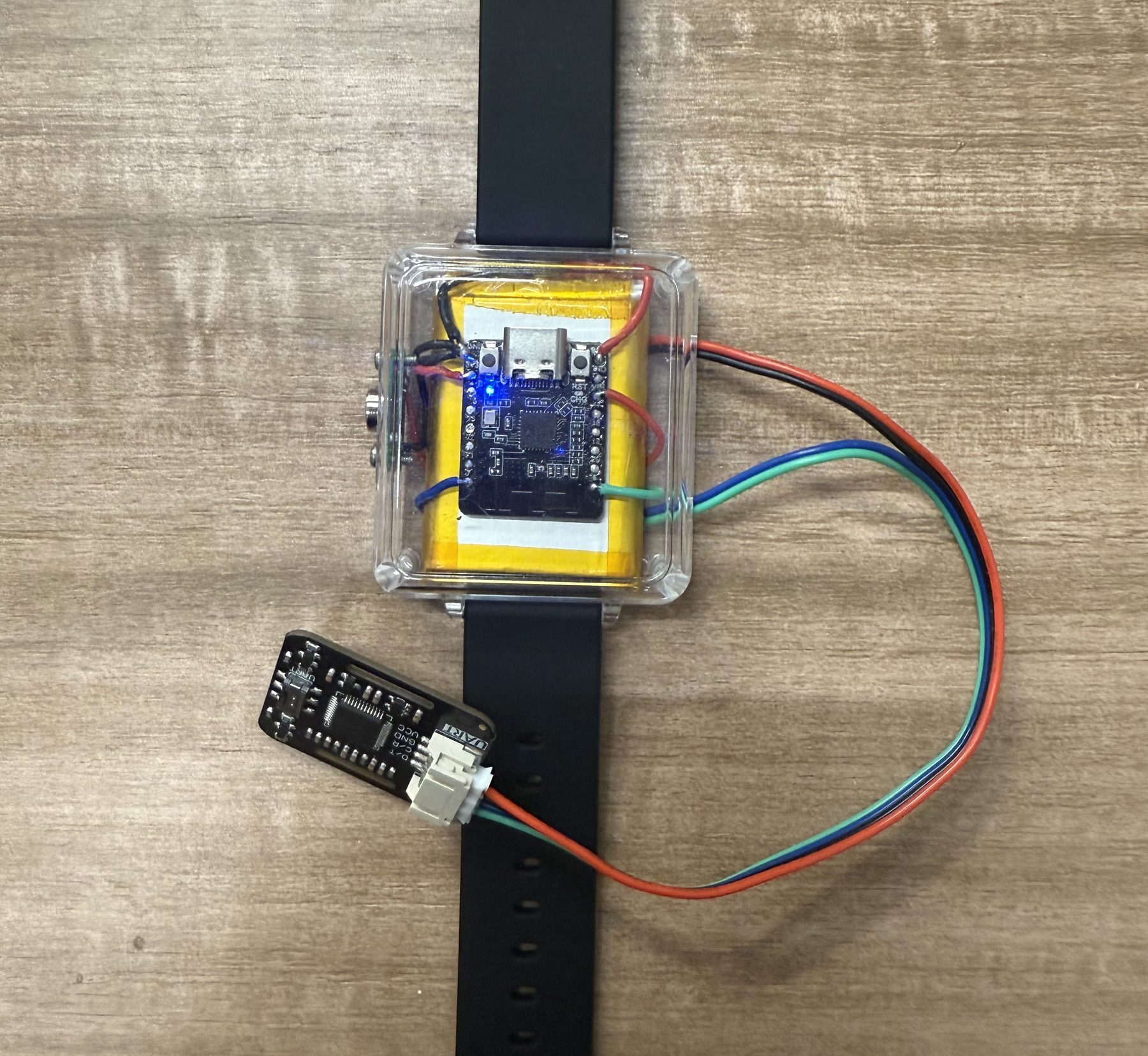
The wearable band uses a Beetle ESP32-C6 and MAX30102 heart-rate / SpO2 module. The Beetle
firmware starts I2C on GPIO6 and GPIO7, reads the sensor at address 0x57, then
advertises seq / hr / spo2 / temp as BLE manufacturer data.
| Part | Signal | Connection |
|---|---|---|
| MAX30102 sensor | SDA | Beetle GPIO6 |
| SCL | Beetle GPIO7 | |
| VCC | 3V3 | |
| GND | GND | |
| Beetle ESP32-C6 | Battery | LiPo through the Beetle charging circuit |
| Beetle ESP32-C6 | Status LED test | GPIO15 in the test firmware |
Packaging
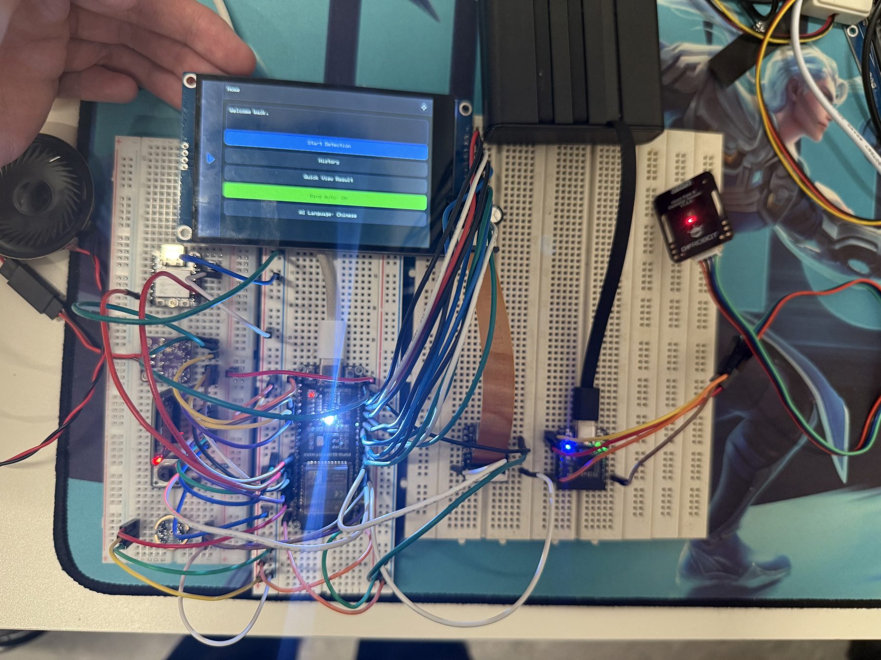
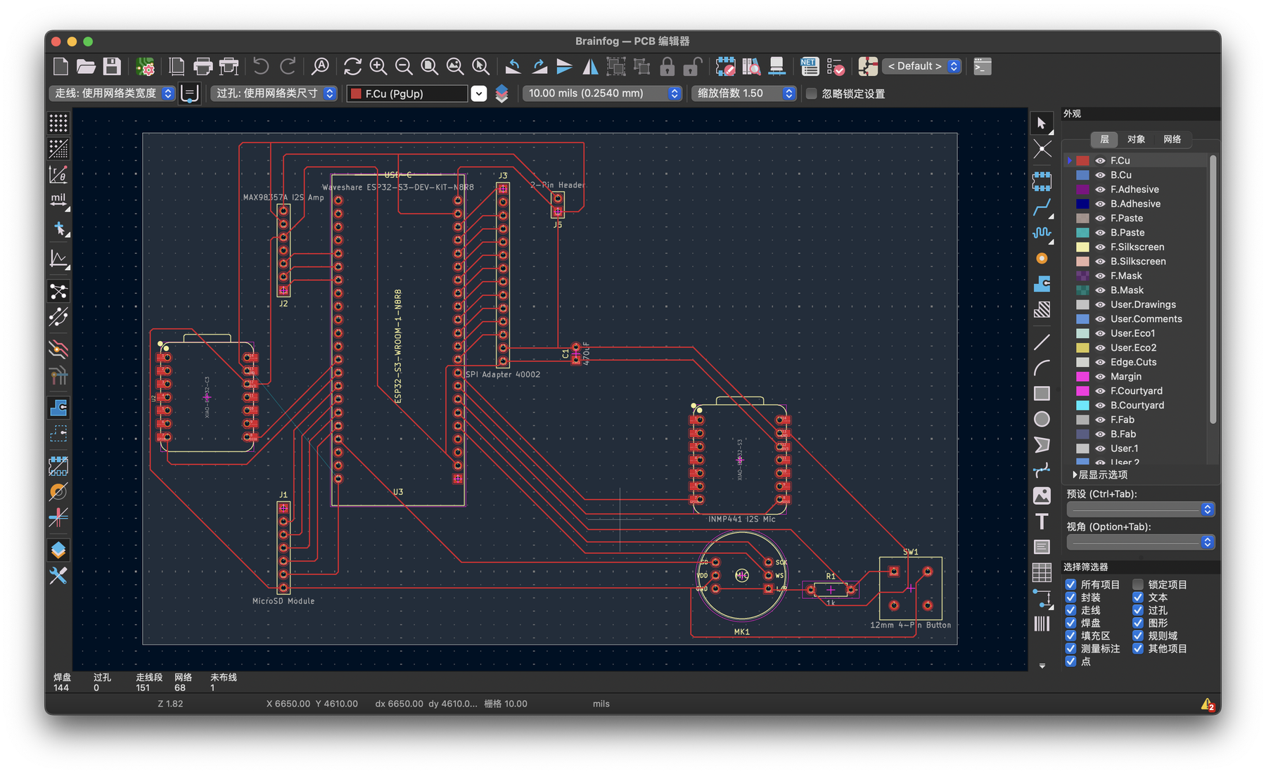
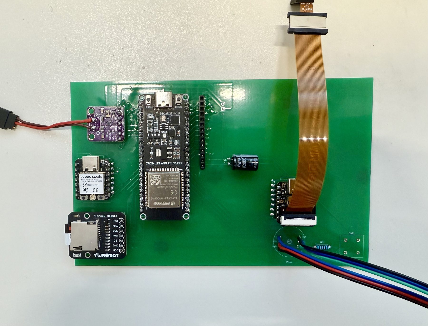
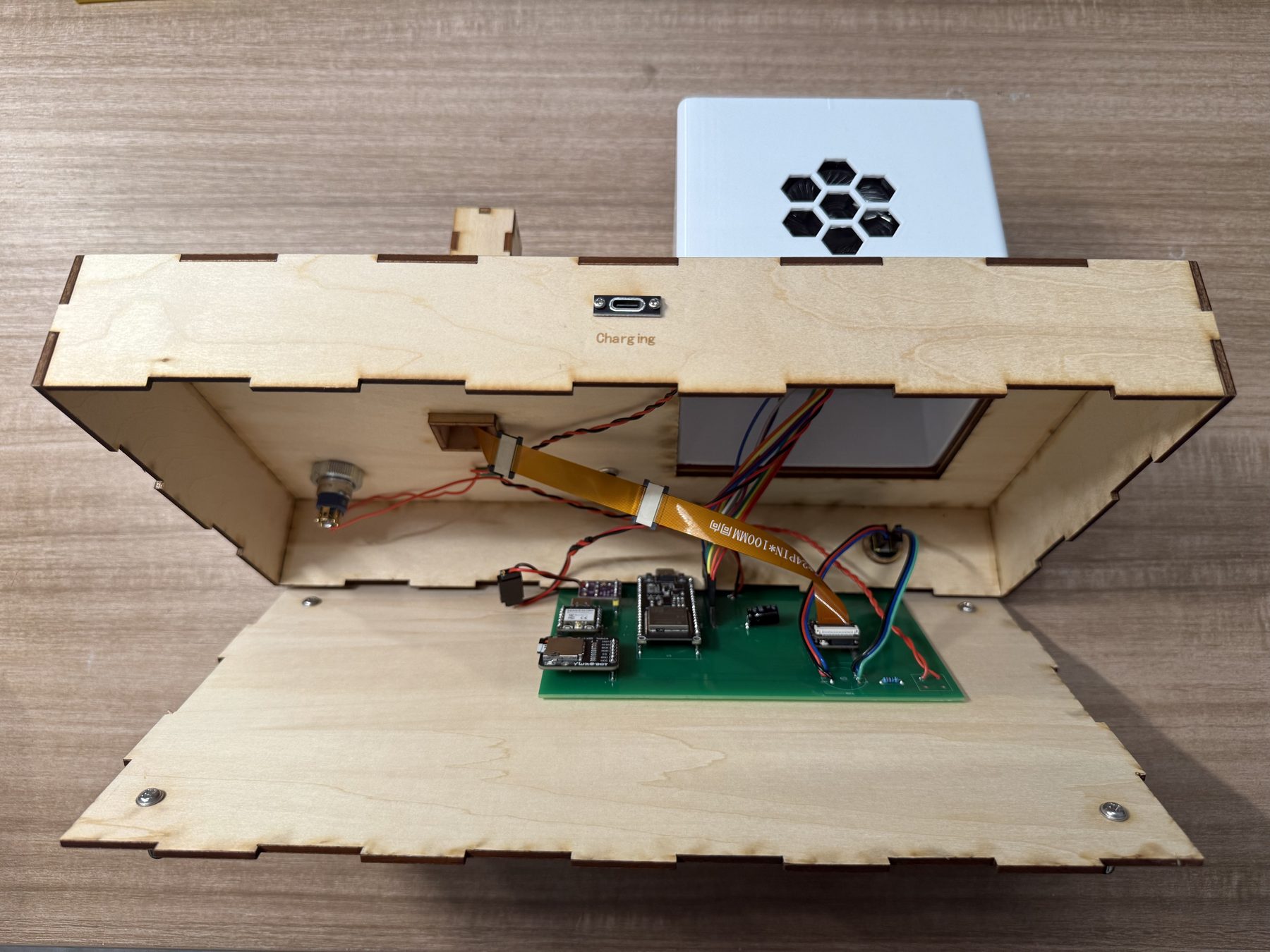
The packaging moved in two stages. First I proved the circuit on a breadboard. Then I moved the host electronics onto my own PCB so the desktop unit could be placed inside the laser-cut platform. The PCB step mattered because the breadboard version worked, but it was too fragile to close into a product-like base.
Physical layout
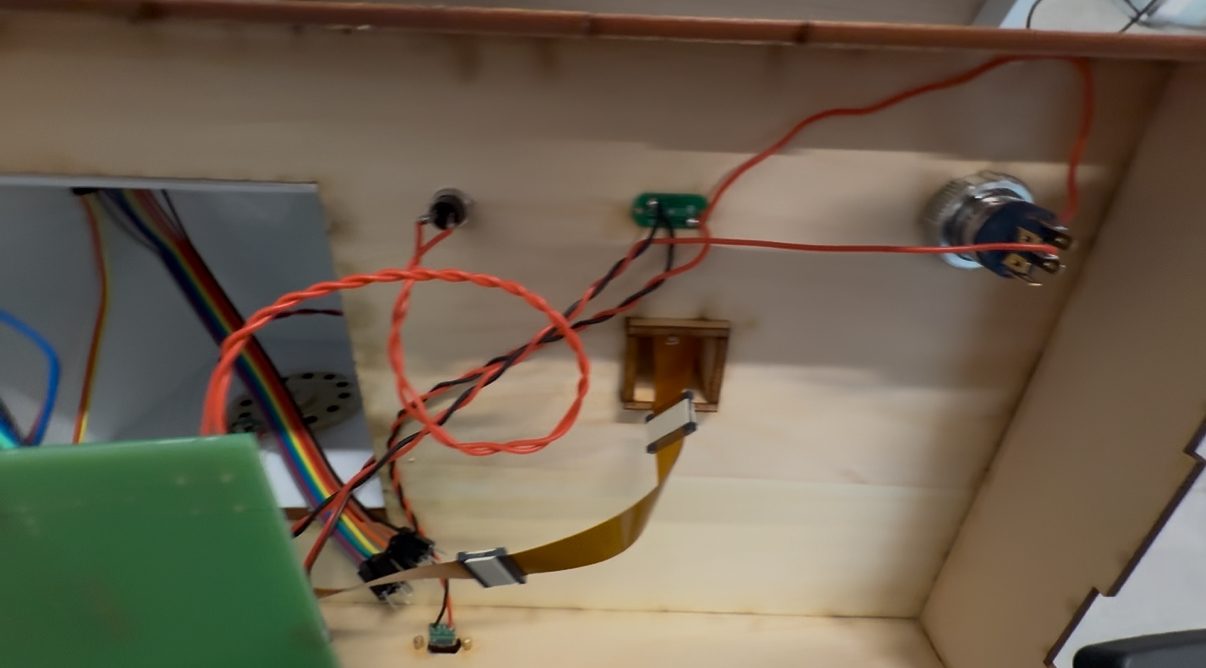
The desktop product is built like a small base station. The laser-cut base carries the load and hides the wiring. The 3D printed shell on the left gives the screen and speaker a fixed home. The camera tower on the right holds the camera at a better viewing height than the base alone. The front charging position keeps the wearable with the host, so the two-device system does not feel like two unrelated prototypes.
Integration test
I tested the whole platform before the bottom cover was closed. This video was not meant to be pretty. It was a practical check: power up, screen on, internal wiring still visible, and the main loop running before I hid the electronics. Catching failures at this stage is easier than reopening a finished platform.
What changed during integration
| Issue | Change | Result |
|---|---|---|
| Breadboard wiring was too loose for a closed platform. | Moved the host electronics to my custom PCB. | The wiring became shorter and easier to mount. |
| The camera needed a stable view of the user. | Added a laser-cut tower on the right side of the platform. | The camera is no longer buried at table height. |
| The wearable could become a separate object and get lost. | Reserved a magnetic charging position at the front. | The wearable belongs to the same physical system as the host. |
| The user needs a quick way to start voice interaction. | Added a front button for proactive dialogue. | The main interaction is available without opening a debug terminal. |
| The host needs a hard power control, but charging should remain possible. | Separated the master switch behavior from the watch charging line. | The desktop host can be switched off while the wearable still charges. |
Repair and access
The platform is not sealed permanently. I kept access to the bottom because the system still needs service: firmware uploads, cable changes, and sensor replacement are normal for this prototype. The Type-C input is on the back so power does not compete with the front controls. The next mechanical improvement would be better strain relief for the internal cables and a cleaner removable bottom panel.
Design source files
The host-shell 3D design is the same enclosure family documented in Week 2 CAD and Week 5 3D printing. For this integration week I added the final electronics source package for the Brain Fog host PCB:
- Download Brainfog KiCad source package - project file, schematic, PCB layout, custom footprints, and DRC/ERC reports.
- 3D host shell design process - same enclosure source family used for the final host shell.
Link to final project
This page documents the system-integration step for the Brain Fog Insight Companion final project. The final project page links back to this week as the packaging and integration record.