This week, we explored the fundamentals of Interface and Application Programming by designing a mobile application capable of communicating with an ESP32 microcontroller. Through this assignment, we learned how to create graphical user interfaces, implement Bluetooth communication, and connect digital interactions with physical devices, opening new possibilities for our final project development.
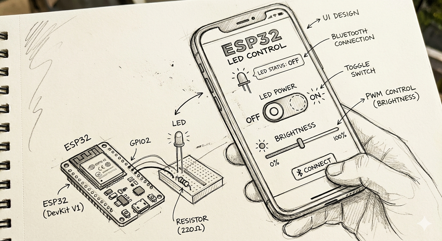
For this week's assignment, we first defined the functionality that we wanted our application to have. Thinking about our final project, we are interested in combining architecture with an interactive lighting system that can be controlled through a mobile application. The main objective of this exercise was to develop an app capable of remotely controlling a set of LEDs through a simple interface, allowing the user to activate the lighting system directly from a smartphone.
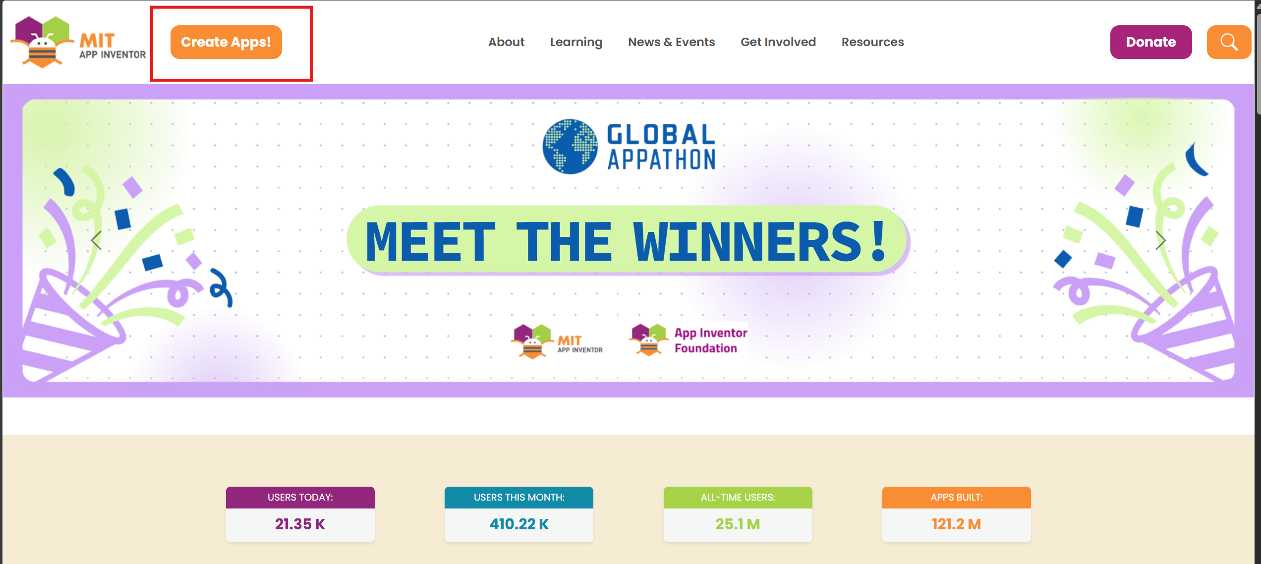
To develop the application, we selected MIT App Inventor, a free and accessible online platform for mobile app development. Since application programming is outside our professional background, we found this software particularly useful because of its intuitive interface and educational approach. The platform allows users to design, test, and program applications directly through a web browser while supporting different screen sizes and mobile devices.
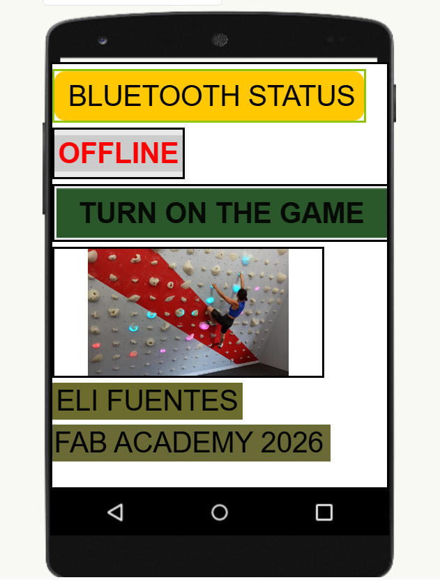
App Inventor also provides a flexible environment for developing a custom graphical interface. We were able to modify colors, typography, labels, buttons, and graphic elements according to the visual identity of the application. This allowed us to create a simple and functional interface adapted to the needs of the project.
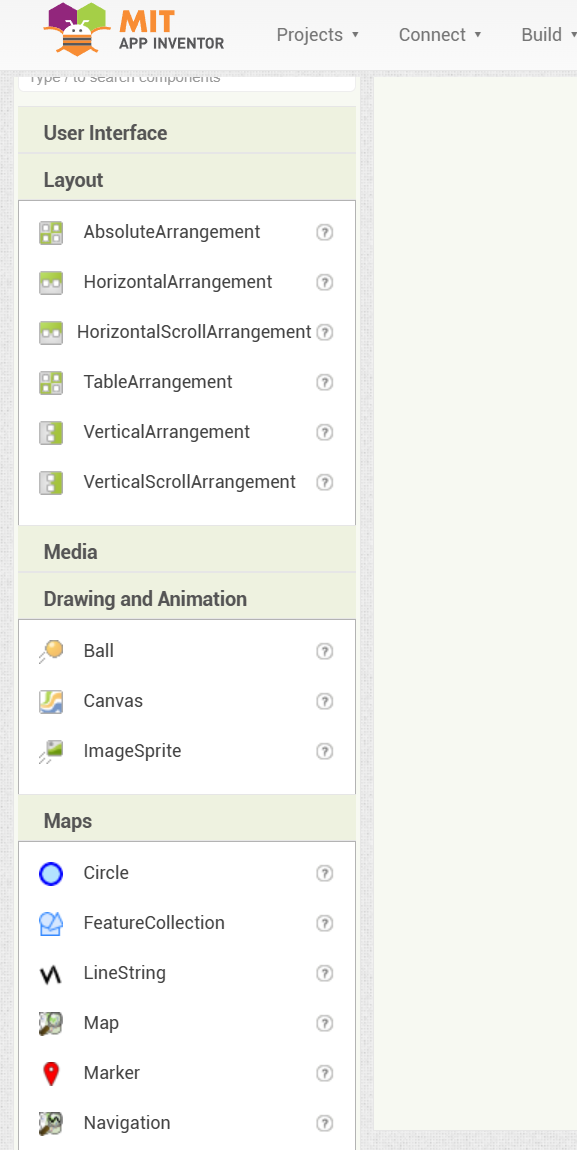
To create the application, we first selected the target device, in this case an Android smartphone. We then added the required interface elements, including buttons, text labels, and graphic components, by simply dragging and positioning them on the workspace. This process made it possible to rapidly prototype the graphical user interface before moving to the programming stage.
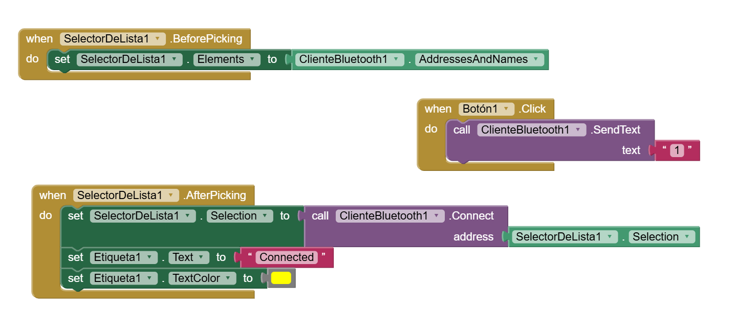
For the programming stage, MIT App Inventor uses a visual block-based programming environment. Instead of writing code manually, logic is created by connecting functional blocks. In our case, we programmed the application to establish a Bluetooth connection with the ESP32 and send commands when the user presses the control button.
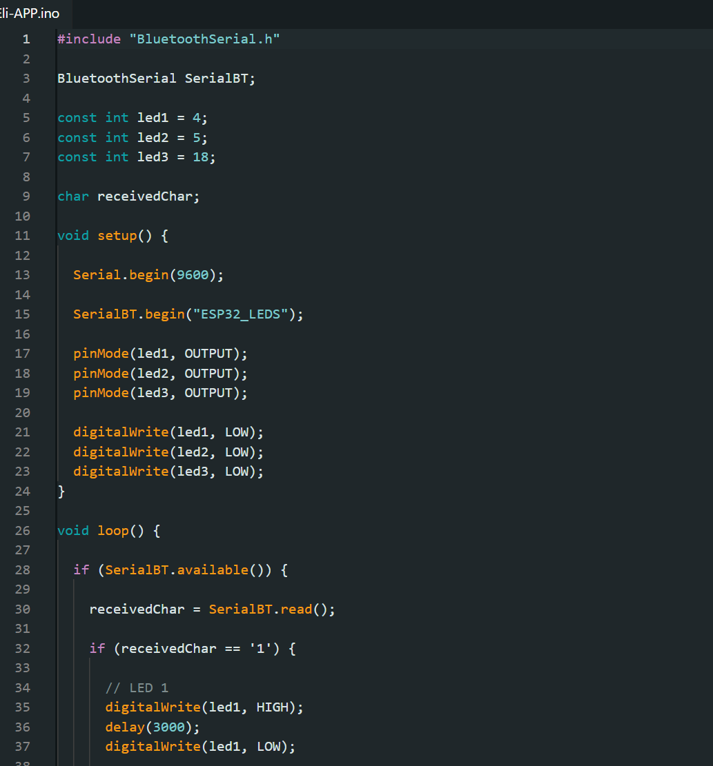
Once the mobile interface was completed, we programmed the ESP32 to receive Bluetooth commands from the application. When the main button is activated, the microcontroller executes a sequence in which three LEDs turn on consecutively, remaining active for approximately three seconds each. This communication workflow is similar to what we plan to implement in our final project, where lighting elements will respond to commands generated from a mobile application.
Finally, we installed the application on an Android smartphone, connected the electronic circuit, established the Bluetooth connection, and tested the complete system to verify the communication between the mobile application and the ESP32.
Conclusions
This assignment introduced us to the process of mobile application development, an area that was completely new to me. Beyond the programming aspect, I particularly enjoyed designing the graphical interface and defining the visual identity of the application. The experience demonstrated how user interaction, interface design, and electronics can be integrated into a single system.
From my perspective as an architect and architecture teacher, I see significant potential in the use of mobile applications for controlling and interacting with built environments. For example, similar technologies could be applied to wayfinding and navigation systems in complex buildings such as hospitals, universities, or transportation hubs, where digital interfaces could help users navigate spaces more efficiently while interacting with smart architectural elements.
Python Graphical User Interface for LED Control
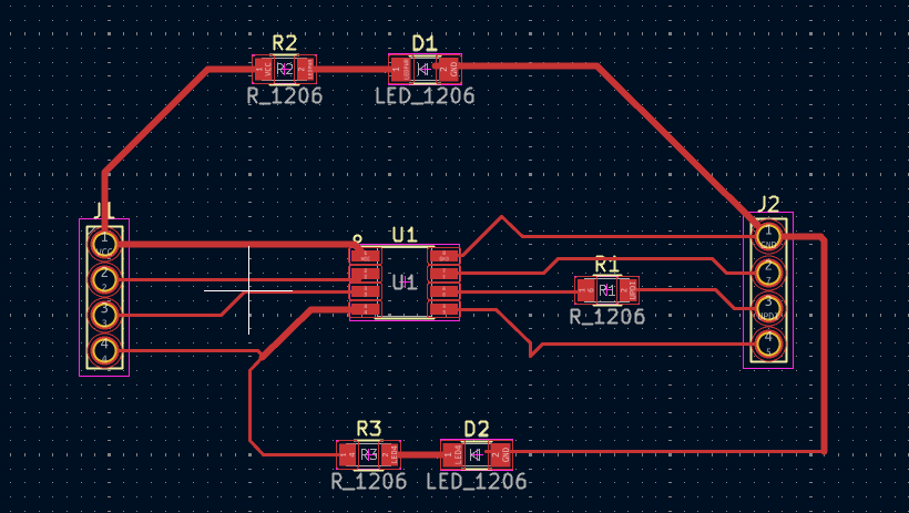
As part of this assignment, I developed a new Graphical User Interface (GUI) using Python to control an LED connected to a custom electronic board. The board was designed and fabricated following the same workflow used during the Electronics Production week, with several modifications intended to optimize space utilization and reduce component requirements.
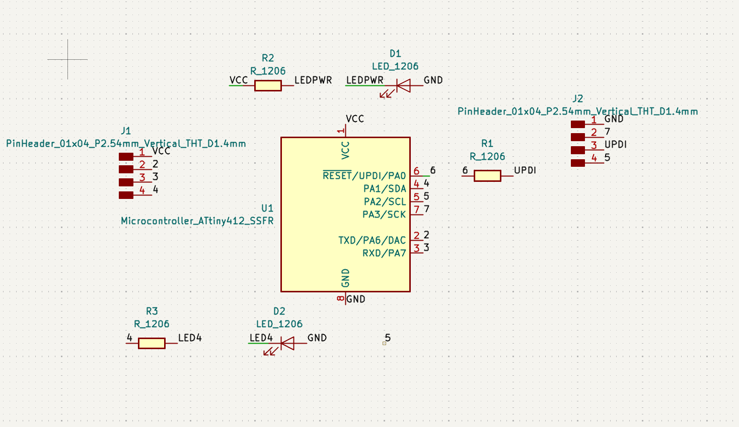
The main improvements introduced in this new version of the board were the reduction of its overall dimensions and the simplification of the circuit. Instead of using multiple indicator LEDs, the design incorporates a single power LED to indicate that the board is energized. Additionally, an extra test LED was connected to physical pin 4 of the microcontroller, allowing rapid verification of uploaded programs and facilitating debugging during development.
Following the same PCB fabrication process documented during the Electronics Production week, I proceeded with the manufacturing of the new circuit board. The design was prepared, milled, and assembled using surface-mount electronic components.
After completing the PCB assembly, including all electronic traces and components, I started developing the desktop application. The software was written in Python and is capable of controlling the LED directly from the computer through serial communication. This setup represents a simplified version of my final project and serves as a test platform for validating communication, programming, and interaction concepts.
Python Installation
The first step was to install Python on the computer using the official installer available at:
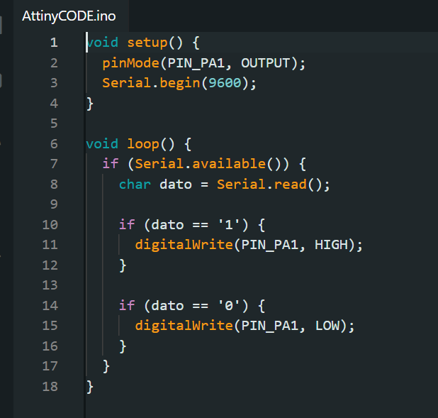
Next, I uploaded the firmware named "AttinyCODE", available in the files section at the end of this page, to the ATtiny412 microcontroller using the UPDI programming interface and an Arduino Nano as a programmer. This procedure follows the same methodology implemented during the Electronics Production week.
Once the firmware was successfully uploaded, the UPDI connection was disconnected and the following serial communication connections were established:
ATtiny412
Arduino Nano
PA6 (TX)
RX
PA7 (RX)
TX
GND
GND
These connections allow the Arduino Nano to function as a USB-to-Serial interface, enabling communication between the Python application running on the computer and the custom ATtiny412 board.
GUI Development
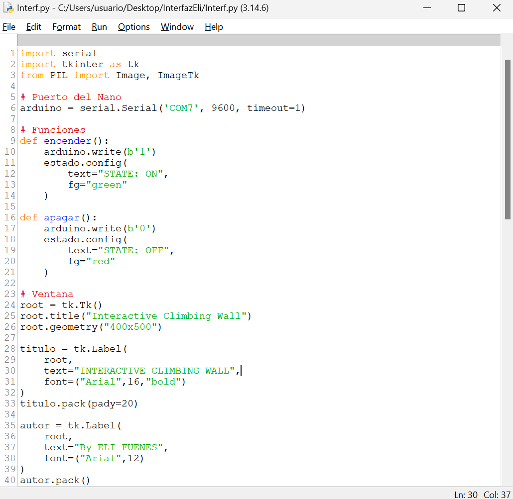
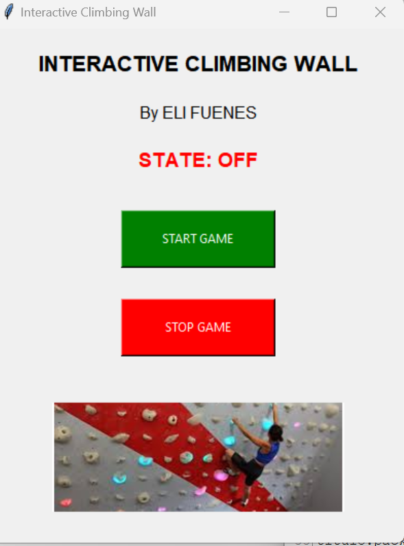
The graphical user interface was developed in Python and includes two control buttons: one to switch the LED on and another to switch it off. Additionally, a status message is displayed within the application to indicate whether the system is currently active or inactive.
The final application provides a simple and intuitive interface for testing serial communication and controlling external hardware through Python.
Final Demonstration
The following video shows the complete operation of the system, including the Python graphical interface, serial communication, and LED control on the custom ATtiny412 board.