Final Project Overview
| Week | Describtion |
|---|---|
| 1 | Idea generatrion and sketch |
| 2 | Idea development, some ditail, intial 3D modeling and printing |
| 3 | Structure research, design development |
| 8 | Concept Rebuild, Research |
| 13 | Midterm plan |
| 14 | Version 1 build up |
| 2026.5.10-6.8 | Final project making speed up |
Week 1 Process
Initial Sketch
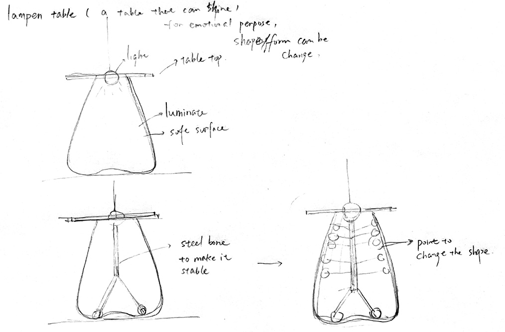 Lampen table / a luminate table
- Evolving from the previous work - Dcell Lamp (2021), the Lampen Table is a dynamic furniture for daily life. Its organic form, shaped by a rotating inner structure, invites touch and play, creating a living interplay of soft light and shadow that transforms with the user.
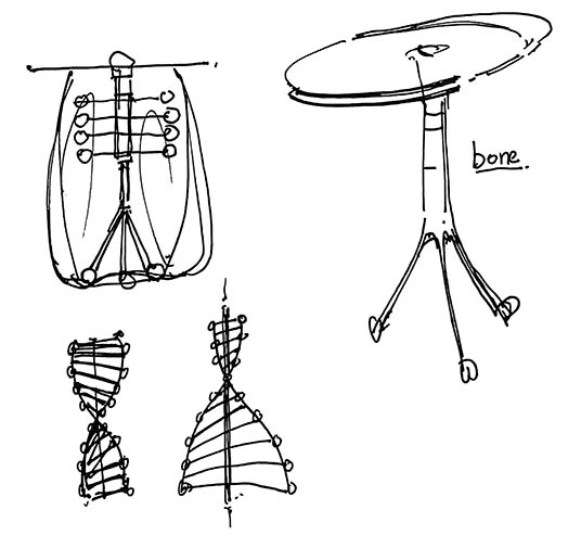
Inspired by Fibonacci Sequence, Ivan Black
I try to make a spin bone inside that it can intractive with the environment by digital control. outside, I will set a skin (might be silicon or TPU) as a packing.
Week 2 Process
The context of the project is showing the primordial digital age. A cell, an embryo, is a metaphor to define the initial of the digital. It is an invasion by the digital world to invade human society. Moreover, it announces that the digital age is coming. It invades our life, not only in the virtual world but also in our physical world.
The lights here are designed to lighten our fears of technology and demolish the anxiety of techno-surprise. A glimmering light is beating. The form looks as if it is a wrapped embryo. It suggests a very human vessel to incubate hope to face the complex world.
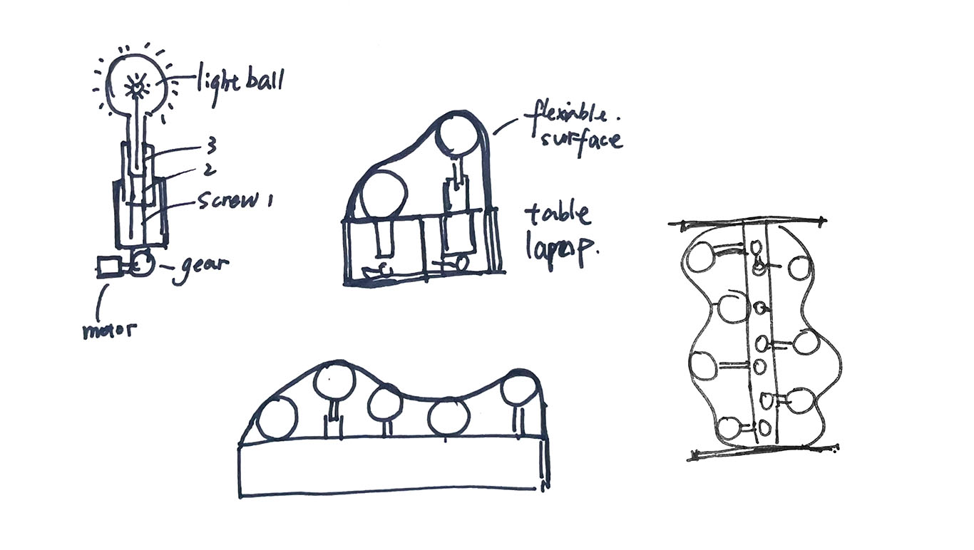
Sketch development
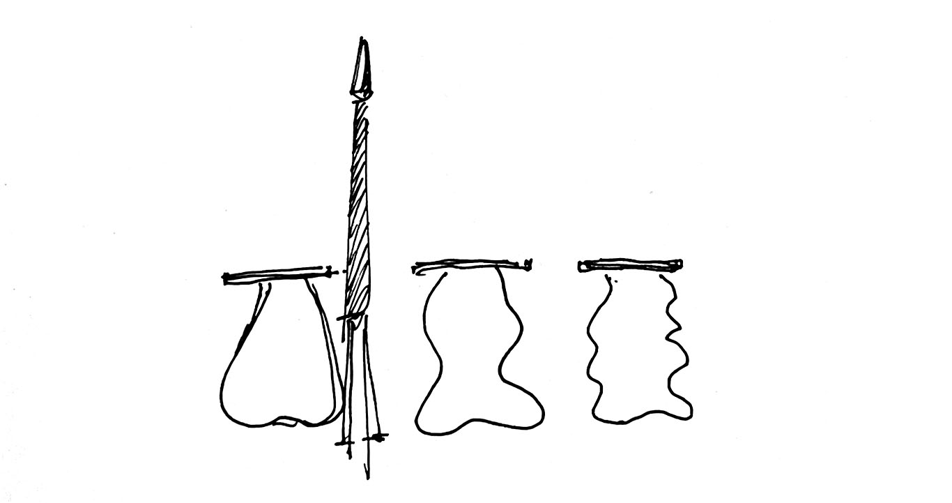 The form will change and lighten when a person passes by.
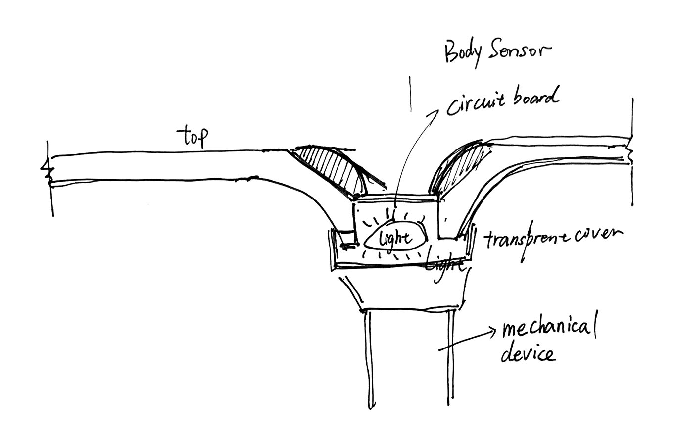 This a core area like a brain that contain circuit boards and sensors to interact with its surroundings.
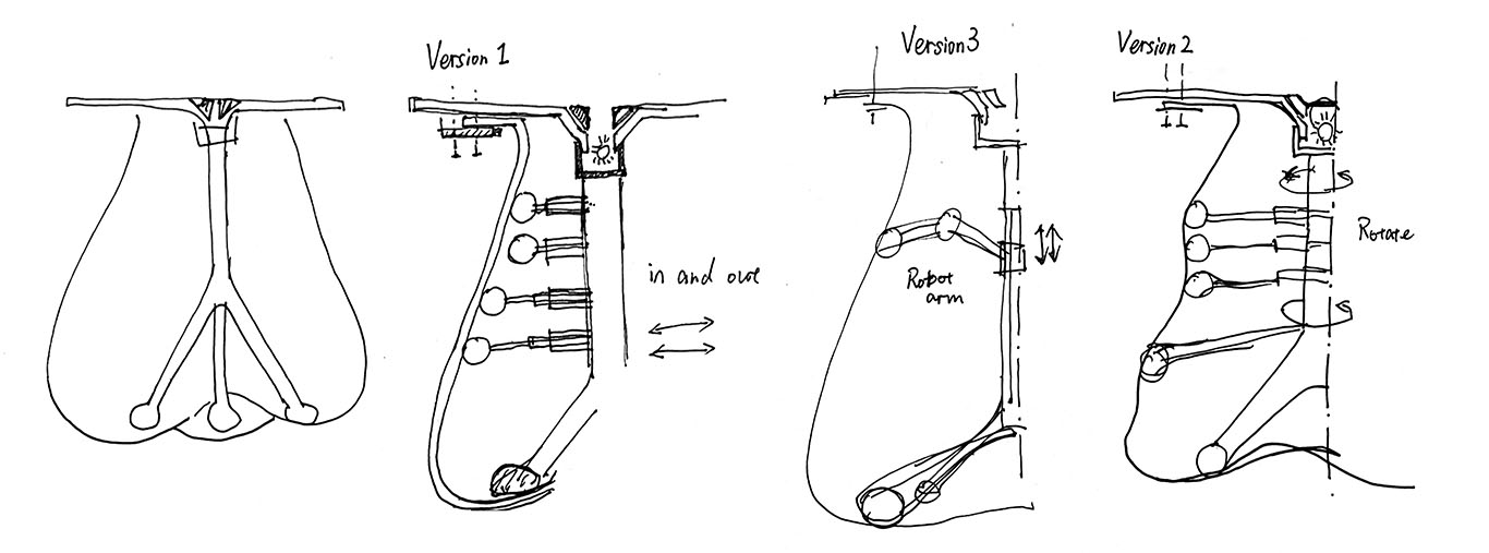
For mechanical part, I have 3 version to judge.
- Version 1: Expansion installation
- Version 2: Rotate installation
- Version 3: Robot arm
For flexible surface
- Casting silicone
- Cloth sewing
- TPU sewing
- 3D print chain mail
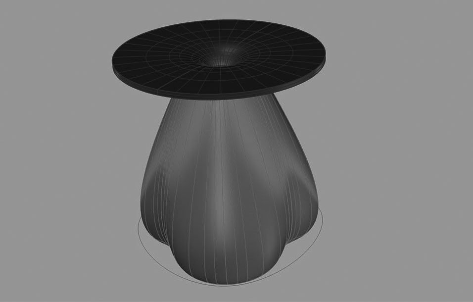
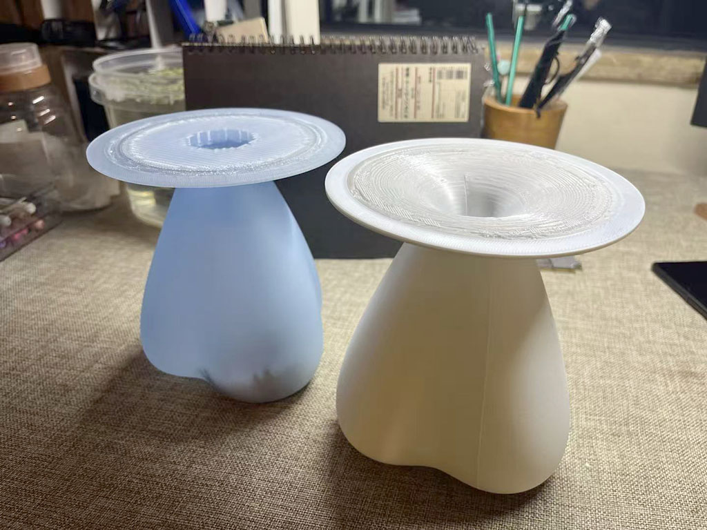
3D modeling and Printing
Week 3 Process
There are several mechanical methods to achieve vertical movement, such as an Ordinary crank motion.
Common Mechanisms for Vertical Movement:
- Lead Screw & Nut System: Converts rotational motion from a motor into precise vertical motion, often used in lifts for high load capacity.
- Scissor Linkage Mechanism: Utilizes a crisscross, X-pattern folding structure to extend or retract vertically.
- Rack-and-Pinion: A pinion gear meshes with a vertical rack, converting rotational motion into linear displacement, often used for moderate vertical distances.
- Belt or Chain Drives: A motor drives a belt or chain to raise or lower a platform, although they require careful safety measures against free-fall.
- Hydraulic/Pneumatic Actuators: Uses fluid pressure to drive a piston vertically.
- Cam & Follower: A rotating cam converts motion to lift a follower vertically, frequently used in automated mechanisms.
An overview of telescopic systems can be seen in this video: Telescopic Machines
(x)Hydraulic
- Prone to leakage and mechanical failure
- Requires regular maintenance and fluid replacement
- Potential environmental and safety concerns with hydraulic fluid
- Generally less precise in positioning
(✓)scrwing machanism (similar to that used in adjustable standing desks)
- More reliable and durable for long-term use
- Clean and maintenance-free operation
- Suitable for consumer-grade products
- Provides precise and stable positioning
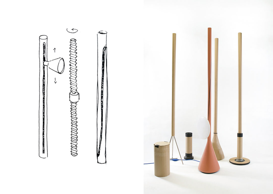
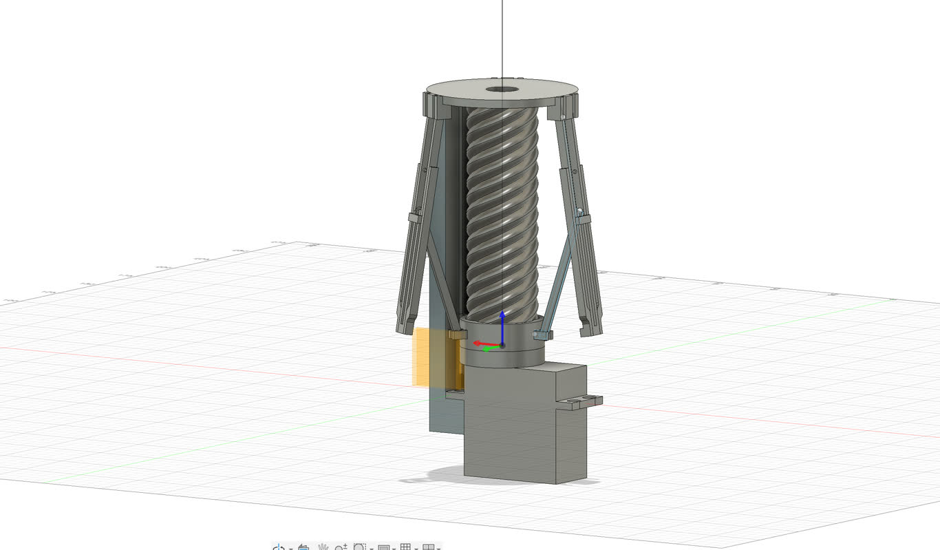
I found a helpful tutorial on screw-driven structures, and believe a 3-stage telescopic screw actuator would be well-suited for the vertical motion part of my design.
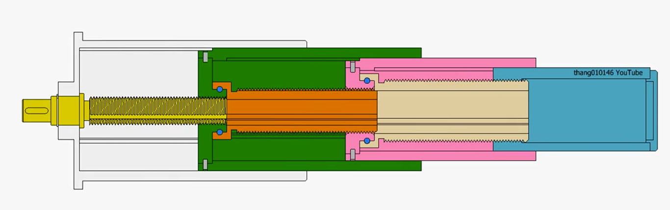
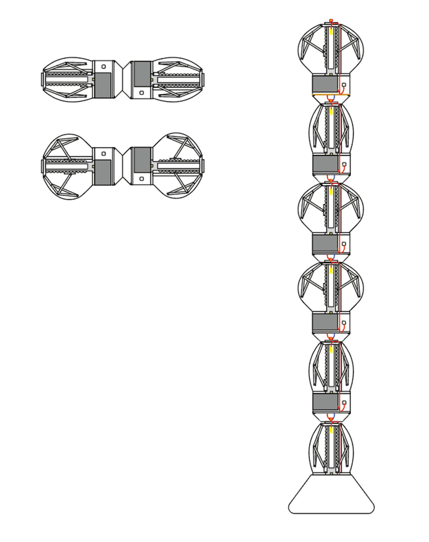
Following a modular design approach, the structure can first be developed as a single mechanical unit. Once completed, multiple units can be arranged in a linear configuration to form a table lamp. If arranged in a mirrored layout, it can be extended into a floor lamp.
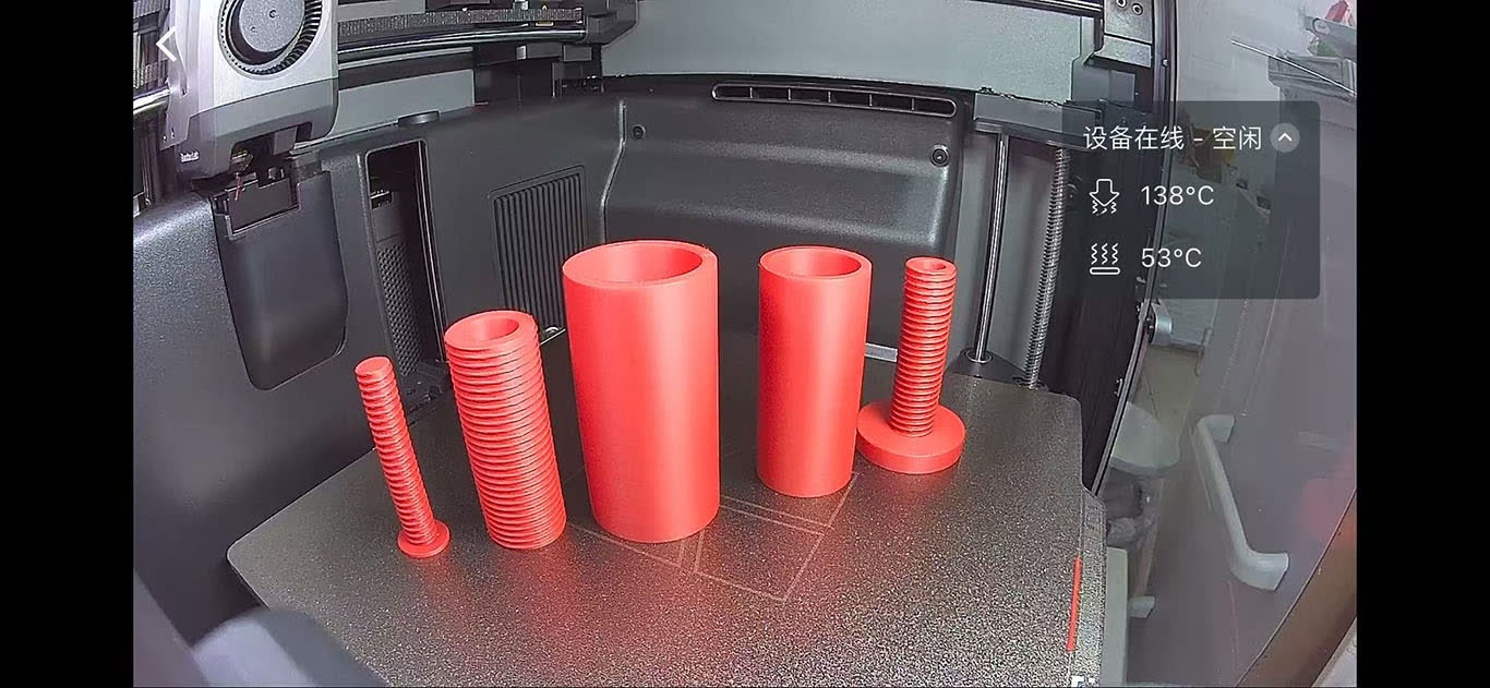
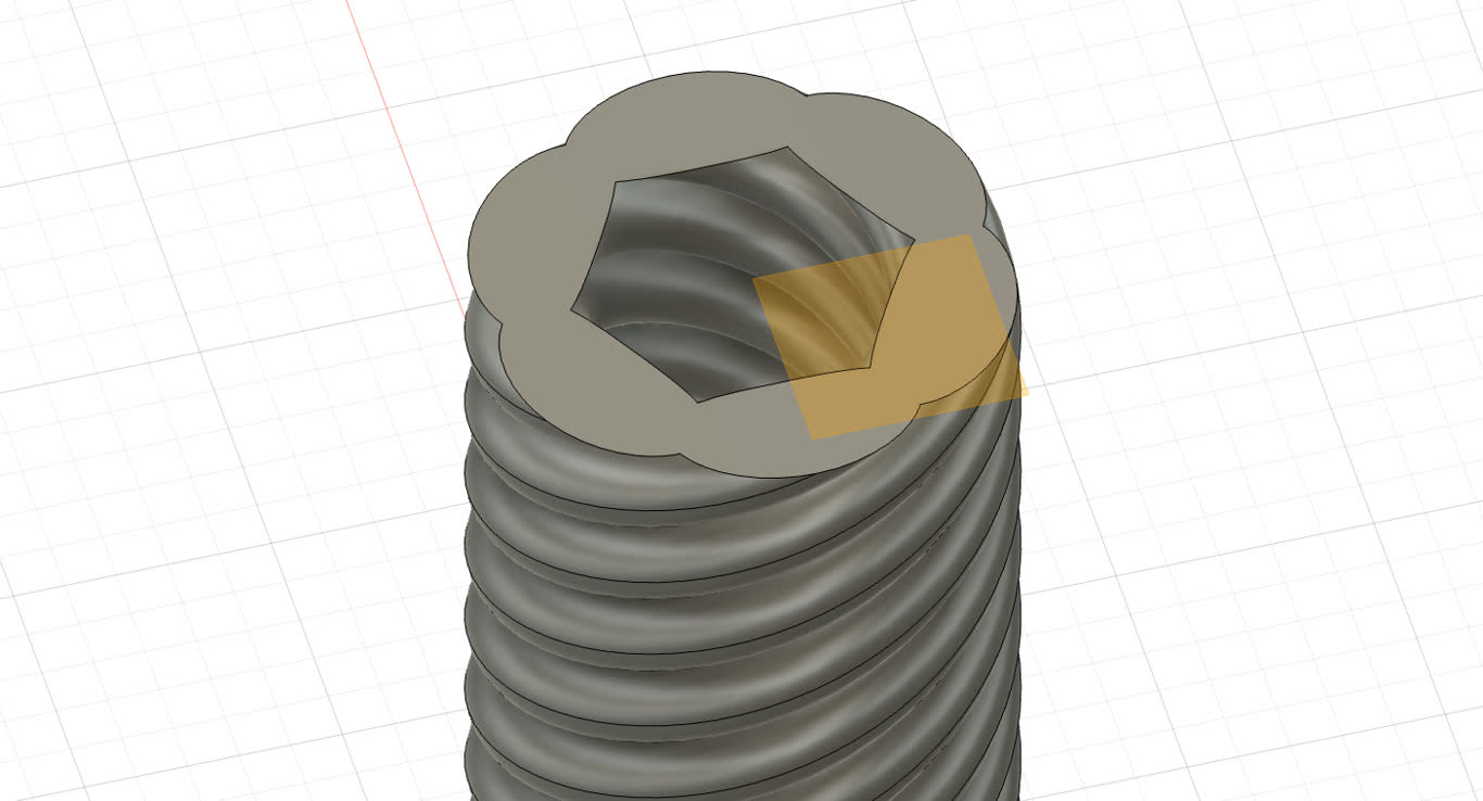
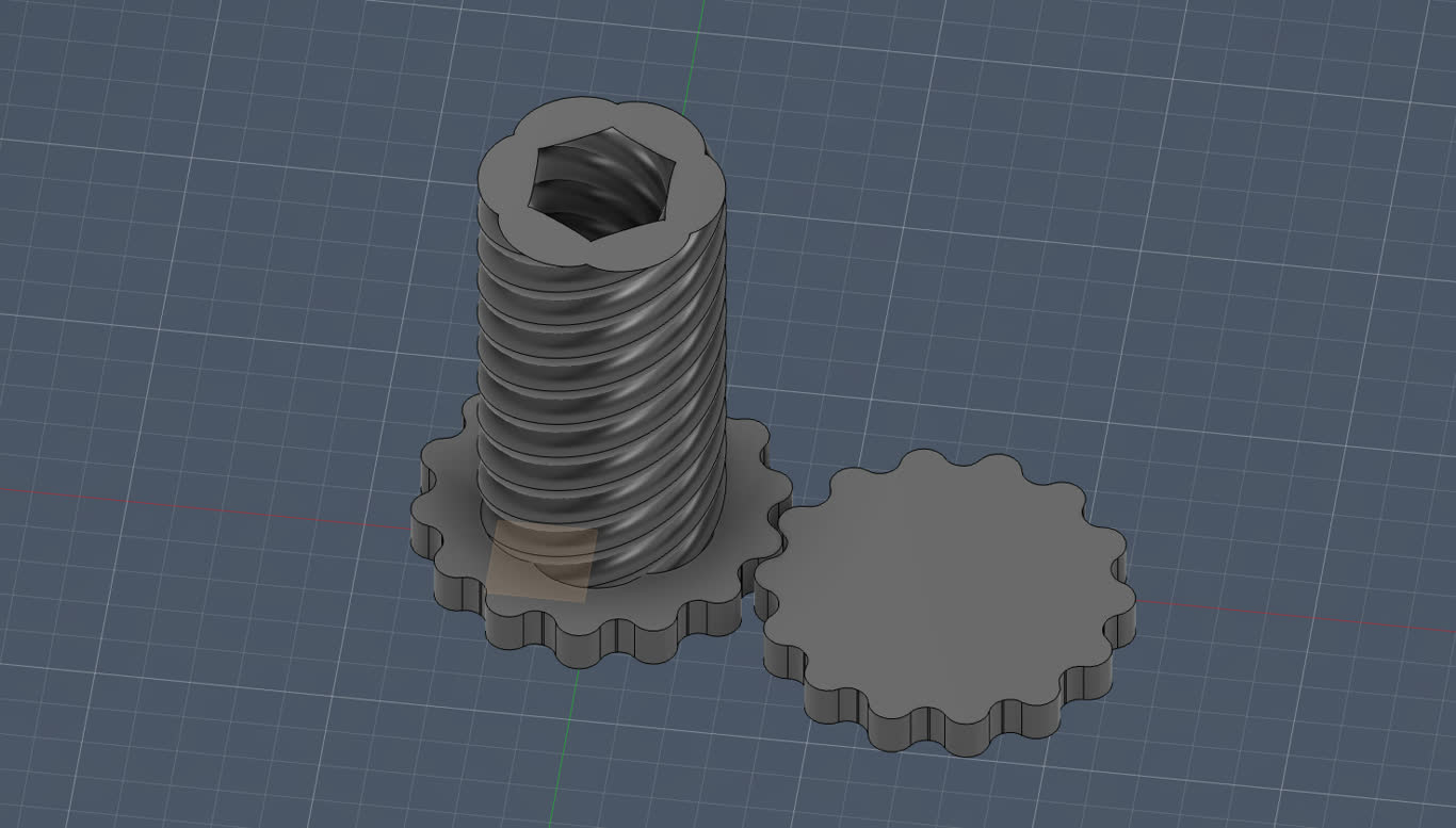
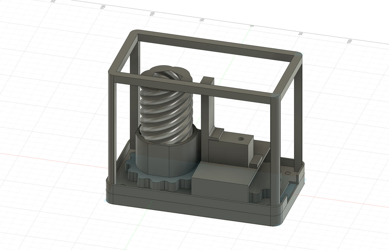
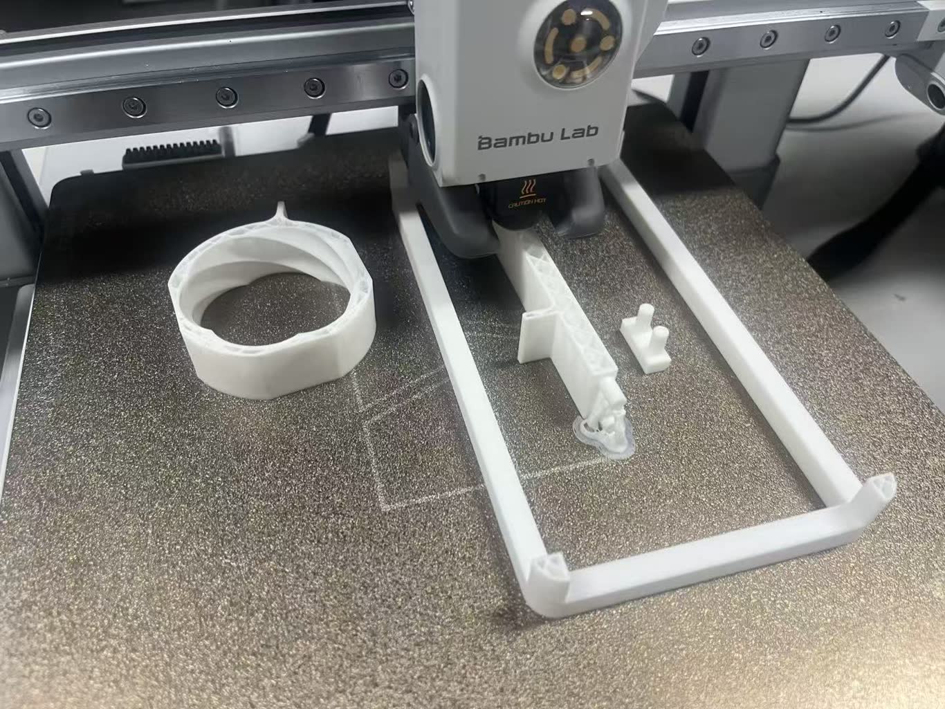
Follow the guid I made a 3D modle for 3 layer telescope structure. But the trouble is too tight to screw. And I got the avdice from instructor.
Issus
- clearance not enough
- 3D print spiral hang in the air, which will droop a little bit may affect the result.
Solution
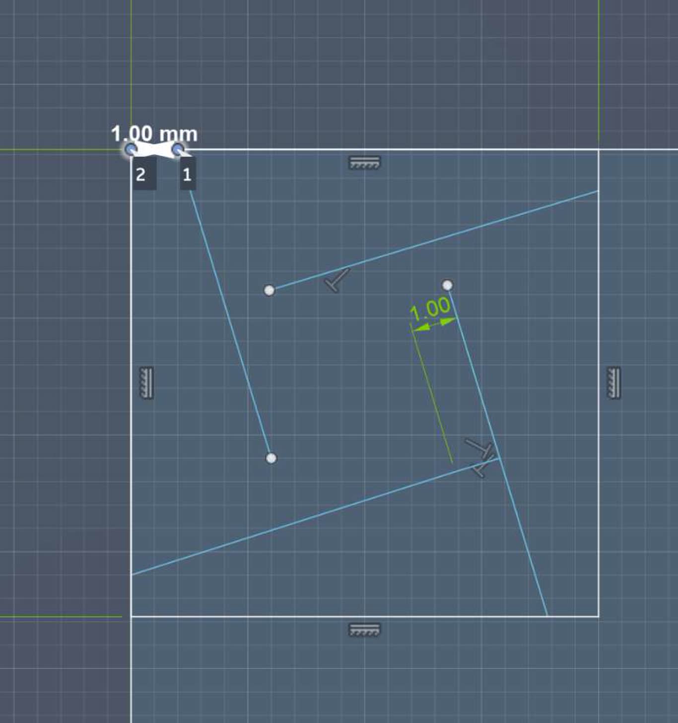
- Increased the clearance
- Remove the unnecessary middle part. Screws will have its flexbility, which may easier to assembly.
- cut the screw in half then joint together to avoid the spiral print in the air
Week 8 Process
Concept Rebuild
I've always wondered: why do we use technology but fear it at the same time? From AI to robots, every new wave of technology makes people uneasy. I don't want to criticize this fear. Instead, I want to use design to make technology gentle and tangible, so people can slowly let go of their unease through interaction.
So I created the Digital Cell Lamp. A cell is the smallest unit of life. I use the lamp as a metaphor for the digital world as an embryo. The lamp has three parts: a base, a shade, and a small inner projection piece-a part users can 3D-print themselves. When the light turns on, this "digital embryo" casts a shadow on the shade. Light dispels fear; the shadow is like a vessel that holds the courage to face a complex world.
I made the projection piece small and easy to produce because I want to turn users from "consumers" into "creators." I also resist the idea that everything has to be minimalist. Life needs complexity; it needs interesting things. This lamp isn't for lighting up a room-it's for creating a small, living moment at home.
I try to design the Lampen Table, a small side table that can change shape.But the mechanism was too complex, so I broke it down into small telescopic units.
I plan to make a table lamp with a row of telescopic rods. Every ten minutes, one rod would push up, lifting a soft silicone surface while the light turned on. Six rods completed one cycle in exactly one hour. I became fascinated by this rhythm-it felt like a heartbeat.
Then I can turn the structure vertically into a floor lamp. The base is in the middle, with rods extending left and right. The right side still moves every ten minutes, while the left side moves only after the right side has completed two hours (one full cycle). This asymmetrical timing made the lamp seem to have a kind of "memory."
Challenge
My current challenge is: how do I make the mechanical structure reliable and easy to produce, while keeping it interesting? I don't want to simplify it until it's boring, nor complicate it until no one dares to touch it.
to let thoughts about the digital age not just stay in the mind, but gently enter daily life-through every change of light and shadow, every deformation, every small interaction between person and lamp. And there, incubate the hope and joy we need to face this complex world.
Clock and lamp Research
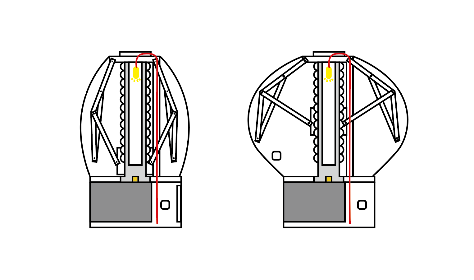
Designed by Kutarq Studio, Totem de Luz is a kinetic lamp distinguished by its fully exposed mechanical system-pulleys, counterweights, and tensioners are all clearly visible. Users physically adjust the light source's vertical position to alter its function: when raised to the top, the light diffuses upward through an onyx diffuser to create ambient illumination; when lowered to the side opening, the beam focuses to serve as task lighting for reading.
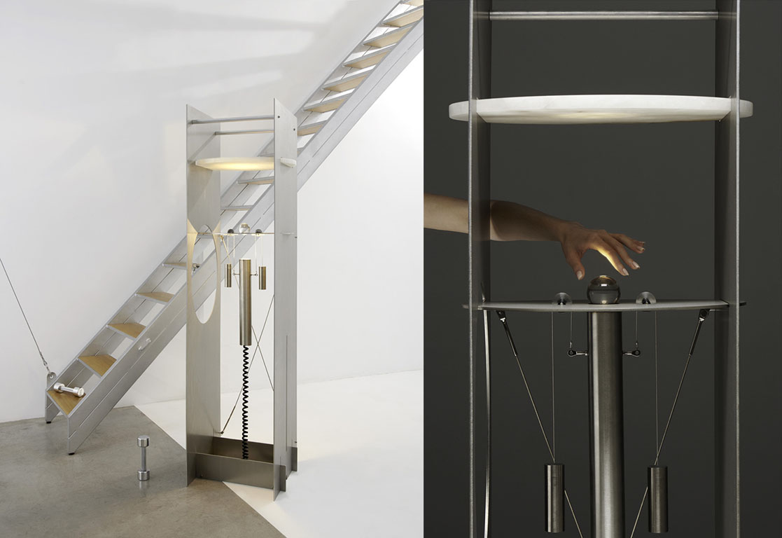
Girasole, a project by Yu-Chun Hsiao from Berlin's Weissensee Academy of Art, is a floor lamp that mimics the characteristics of natural light. It employs a lead screw mechanism to slowly raise and lower an LED panel along an aluminum tube while enabling horizontal rotation, simulating the sun's trajectory throughout the day - from warm-toned low angles at dawn, to cool-toned high angles at noon, and back to warm hues as it descends at dusk.
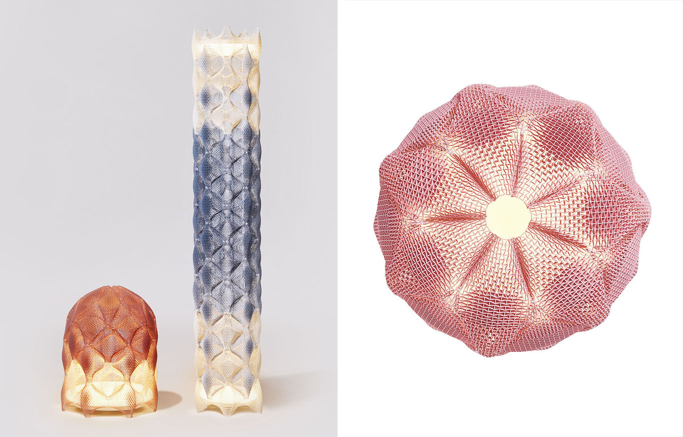
Prinx-3D Printed Modular Re-entrant structures Lamp
The core innovation lies in the use of auxetic structures - these materials expand laterally when stretched rather than contracting, exhibiting a negative Poisson's ratio. By controlling the thickness and design of the modules, the designer achieves precise control over deformation. The lamp consists of three distinct modules that can be assembled into various configurations.
Week 13 Process
Midtern plan click here
Preparation
| Input | Output | Mechanical | electrnical | GUI | Network | Packing | |
|---|---|---|---|---|---|---|---|
| Version 1/"Exclamation Point" | RIP sensor | Servo motor | Twist gear | commercial board | 3D print | ||
| Version 2/"Time wave" | RCT/RIP sensor | Servo motor | Twist gear | PCB board/circuit design | Bus driver | 3D print/casting | |
| Version 3/"Wave reaction" | RCT/RIP sensor | Servo motor | Twist gear | PCB board/circuit design | Web control | Bus driver | 3D print/casting |
Time schedule
2026.5.10 / Version 1
- 2026.5.4 / 3d design (mechanical design)
- 2026.5.6 / electronical design / mechanical prototype making
- 2026.5.8 / embeding programing
- 2026.5.10 / Version 1 demo
2026.5.18 / Version 2
- 2026.5.12 / 3d design (mechanical design)
- 2026.5.14 / surface design and prototype making
- 2026.5.16 / electronical design and embeding programing
- 2026.5.18 / Version 2 demo
2026.5.31 / Final version (Version 3)
- 2026.5.21 / 3d design (mechanical design)
- 2026.5.25 / electronical design and embeding programing
- 2025.5.28 / surface design and making
- 2026.5.30 / Final version testing
- 2026.5.31 / Video shooting
Week 14 Process
2026.5.3
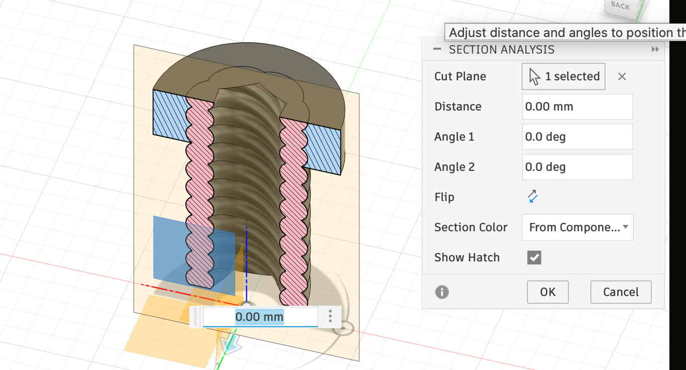
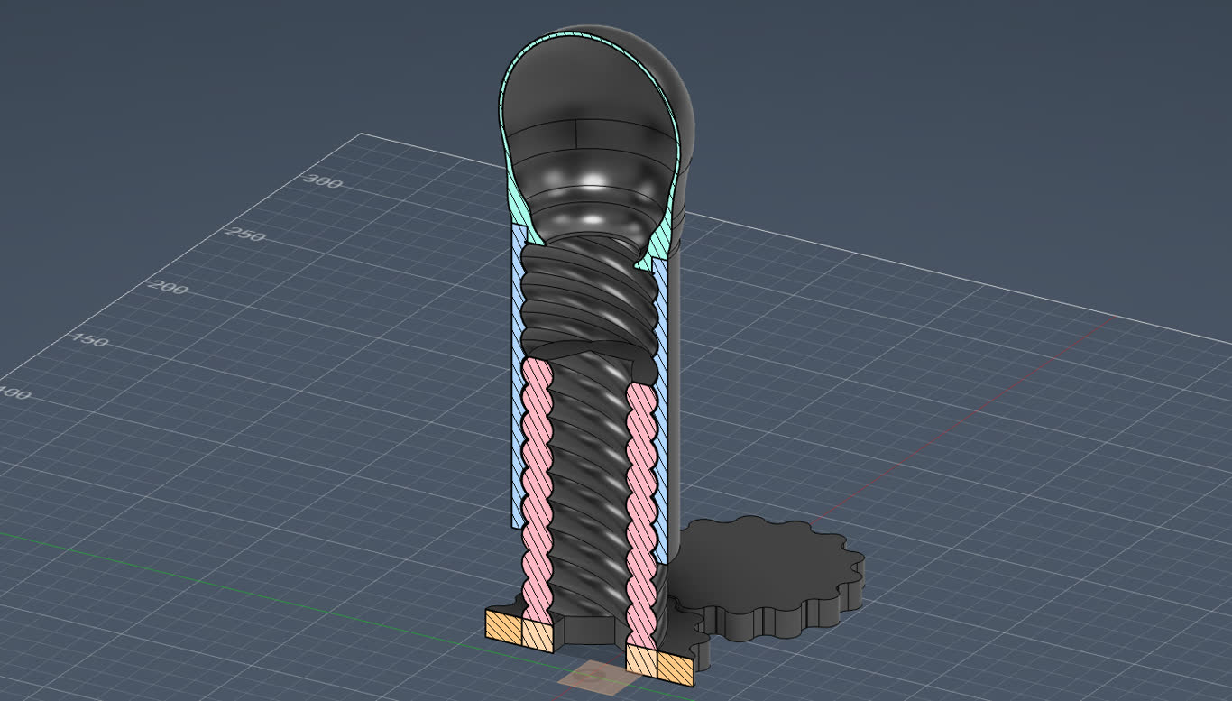
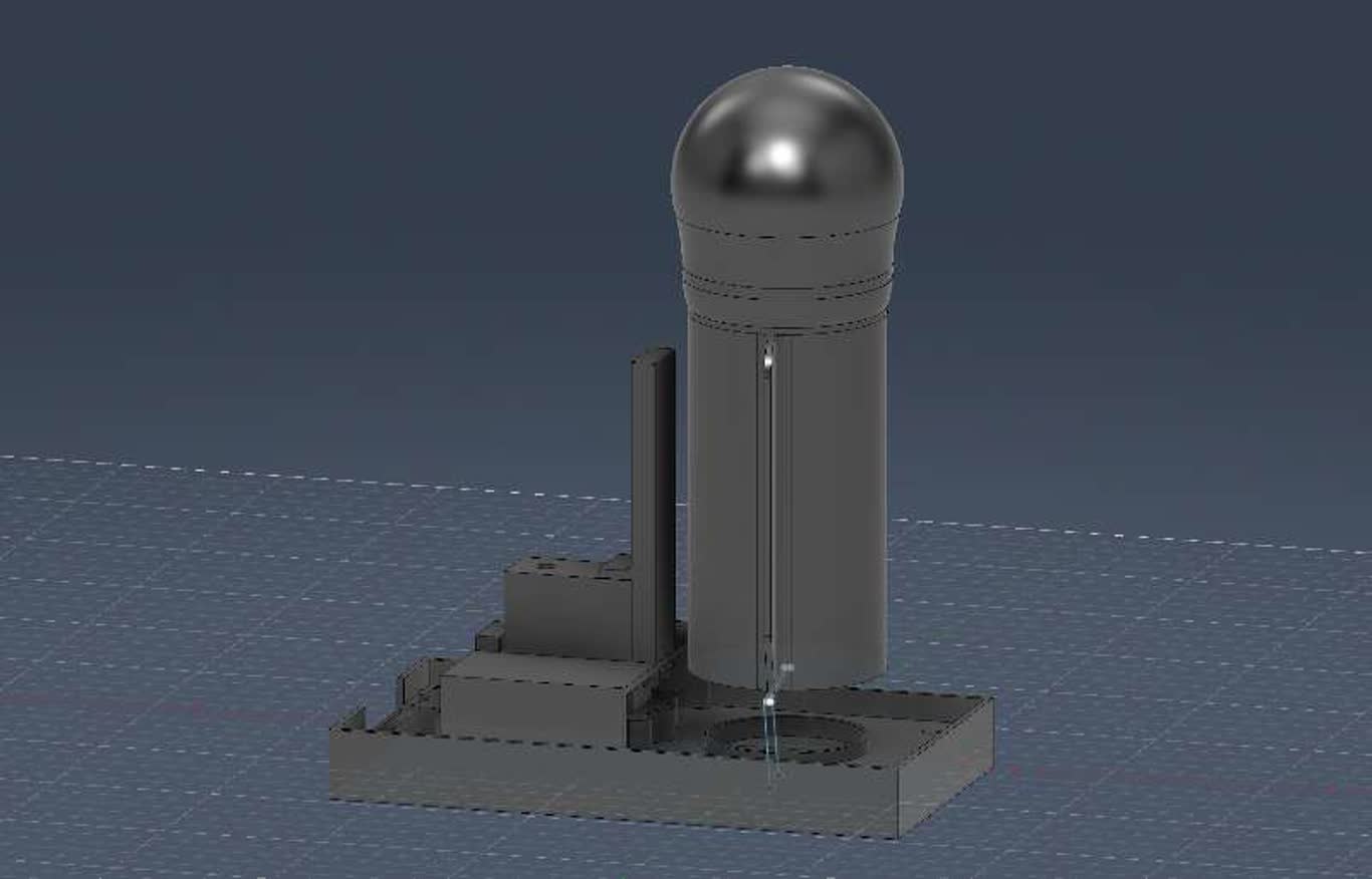
Section ansylsis
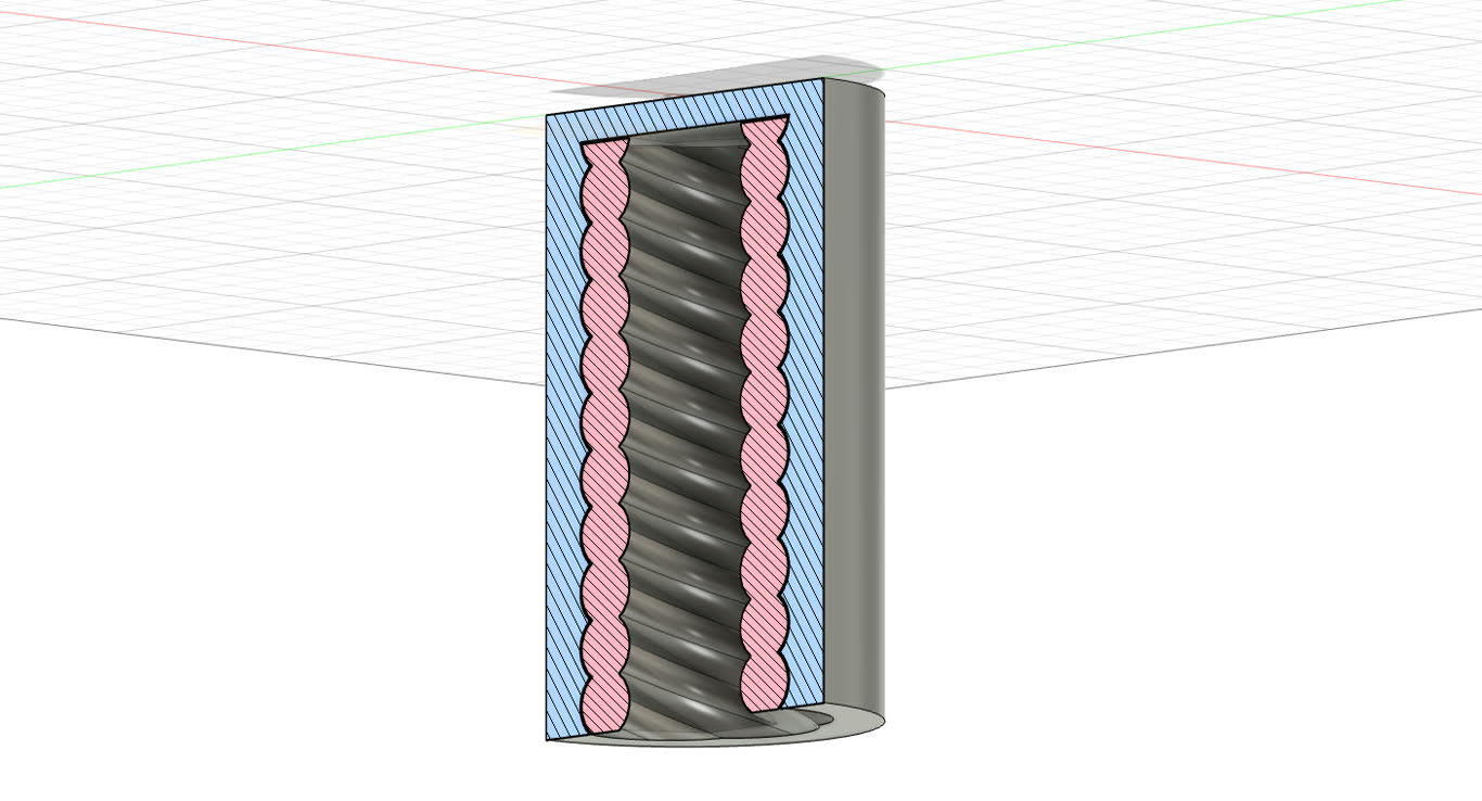
offest surface to create clearance
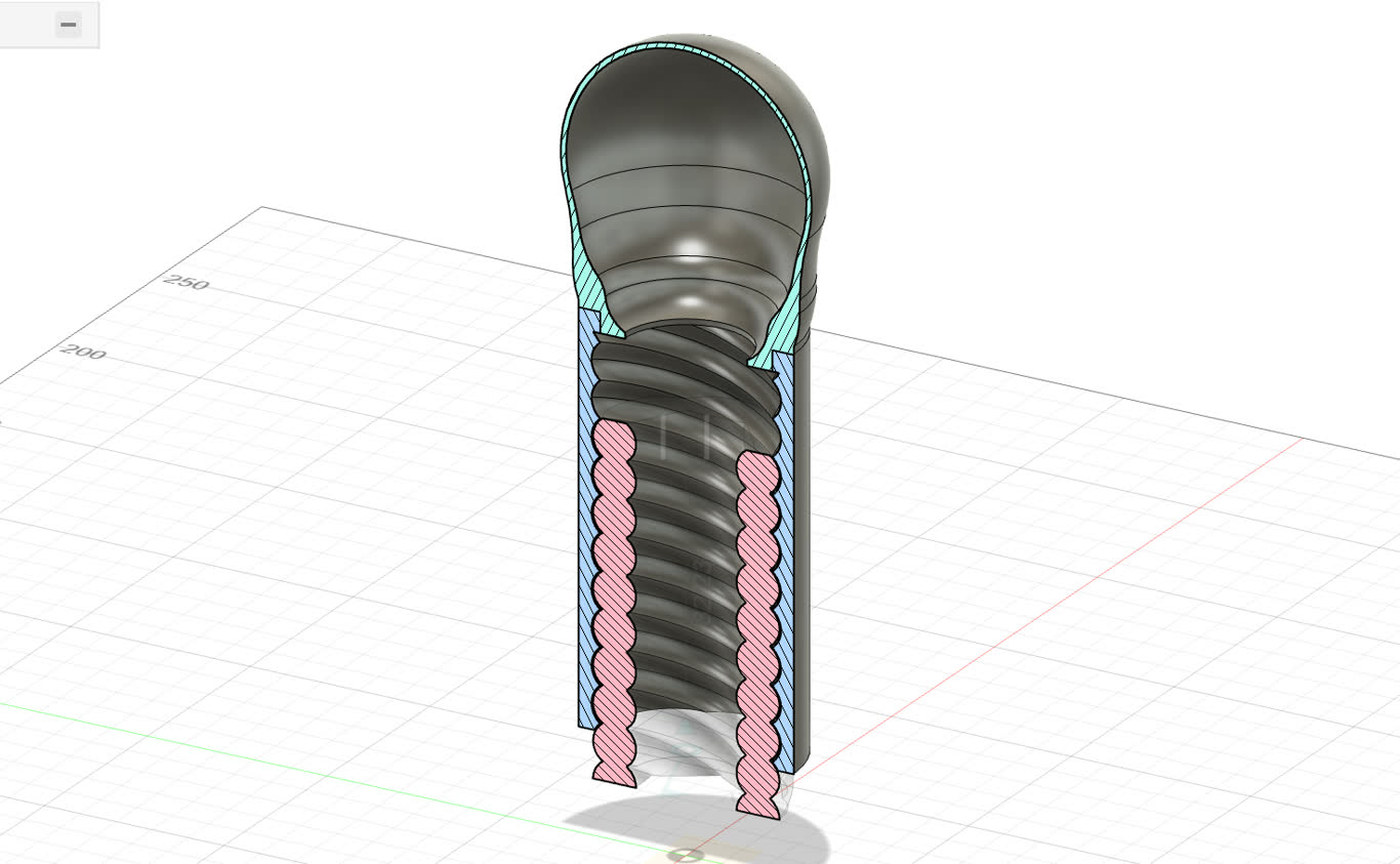
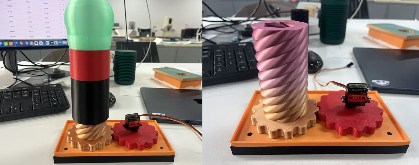
Make a light ball
Set gear to drive the rotary rise
2026.5.10
Soft surface research
In simple terms, Auxetic materials are structures with a Negative Poisson's Ratio (NPR).
Unlike conventional materials (like a rubber band) that get thinner when you stretch them, auxetics do the opposite: they get wider when stretched.
This "counter-intuitive" behavior is achieved through their internal geometric structure (like re-entrant hexagons or rotating squares) rather than their chemical composition.
FAB14 Workshop: Digital Mechanical Material by Design, a physicist approach
Modeling
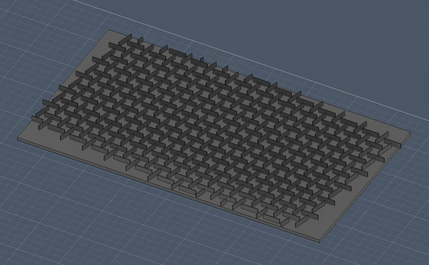
Casting
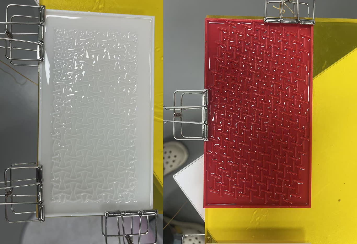
2026.5.11
The basic function has been completed. When a person moves, the motor drives the lever to rise, and at the same time, the LED lights up. When no one is moving, the lever falls back and the lights go out.
2026.5.13
The frictional damping was too high. So I reduced the weight of the lever. At the same time, we also attempted to apply this coating.
2026.5.15
I've realized that I've hit a dead end. The outcome is not satisfactory. The movement of the parts up and down no longer makes sense. The visual effect and the design of the casing are also not ideal.
So I sent Gemini my materials, the problems I encountered, my recent thoughts on the final project, and the current progress for discussion. I wanted to figure out where my issues lay and how I should modify and improve going forward. Since time was also quite limited, I also made a further plan for the schedule.
One of the ideas involving exoskeletons was agreed upon by me and Gemini. Here, some implementation could be possible. The sliding rods that can move up and down can drive a connecting rod, causing the outer skin to expand in an umbrella-like shape. As a result, the outer skin can achieve the effect of contraction and expansion.
2026.5.16
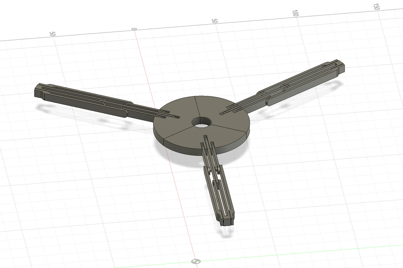
Base on the idea, I need to update and test the new structure.
Then I use Fusion 360 to build up a base model have a check
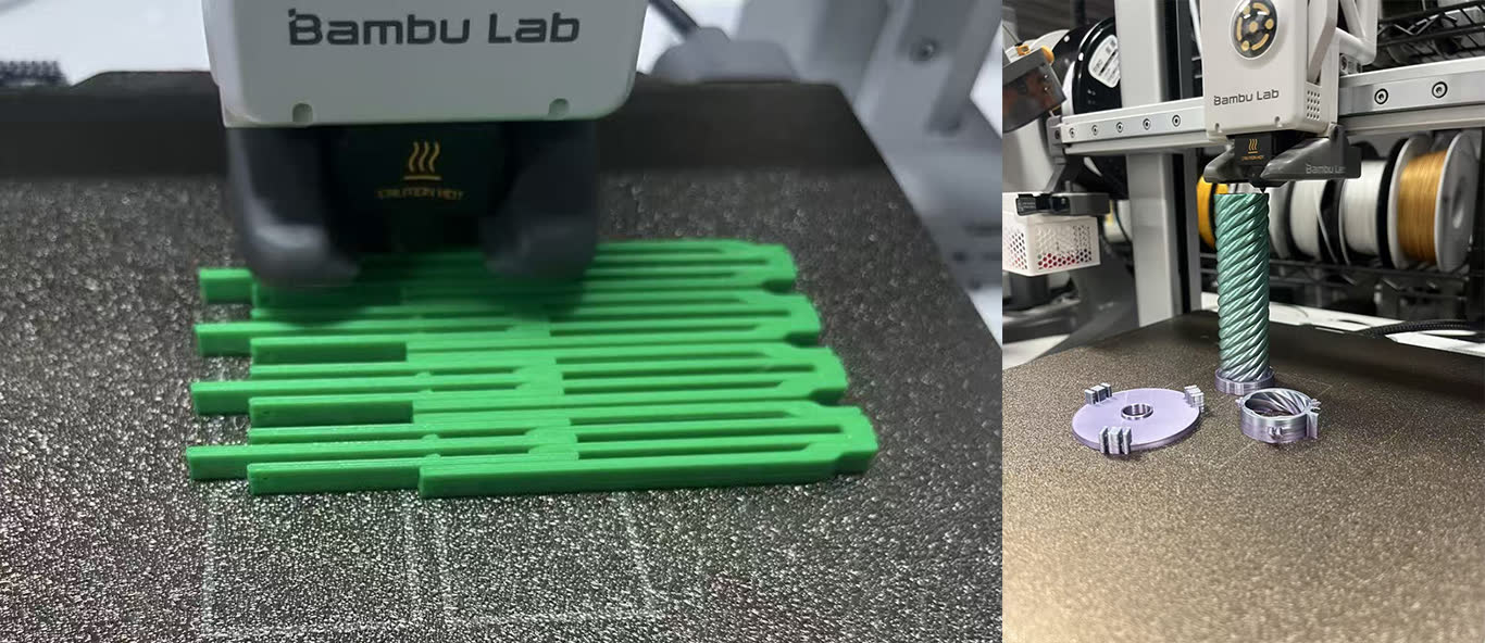
The first try were faild. The joint were not very well, and the structure was fragile. So I am thinking why not just print the connection together.
2026.5.17
I simplise the assamble method. The connection print together.
A nice and smooth slider after I assmble them together. But the mechanical structure is not stable, which move randomly.
The fold of umbrella is the simliar structure. I can learn and find something from it.
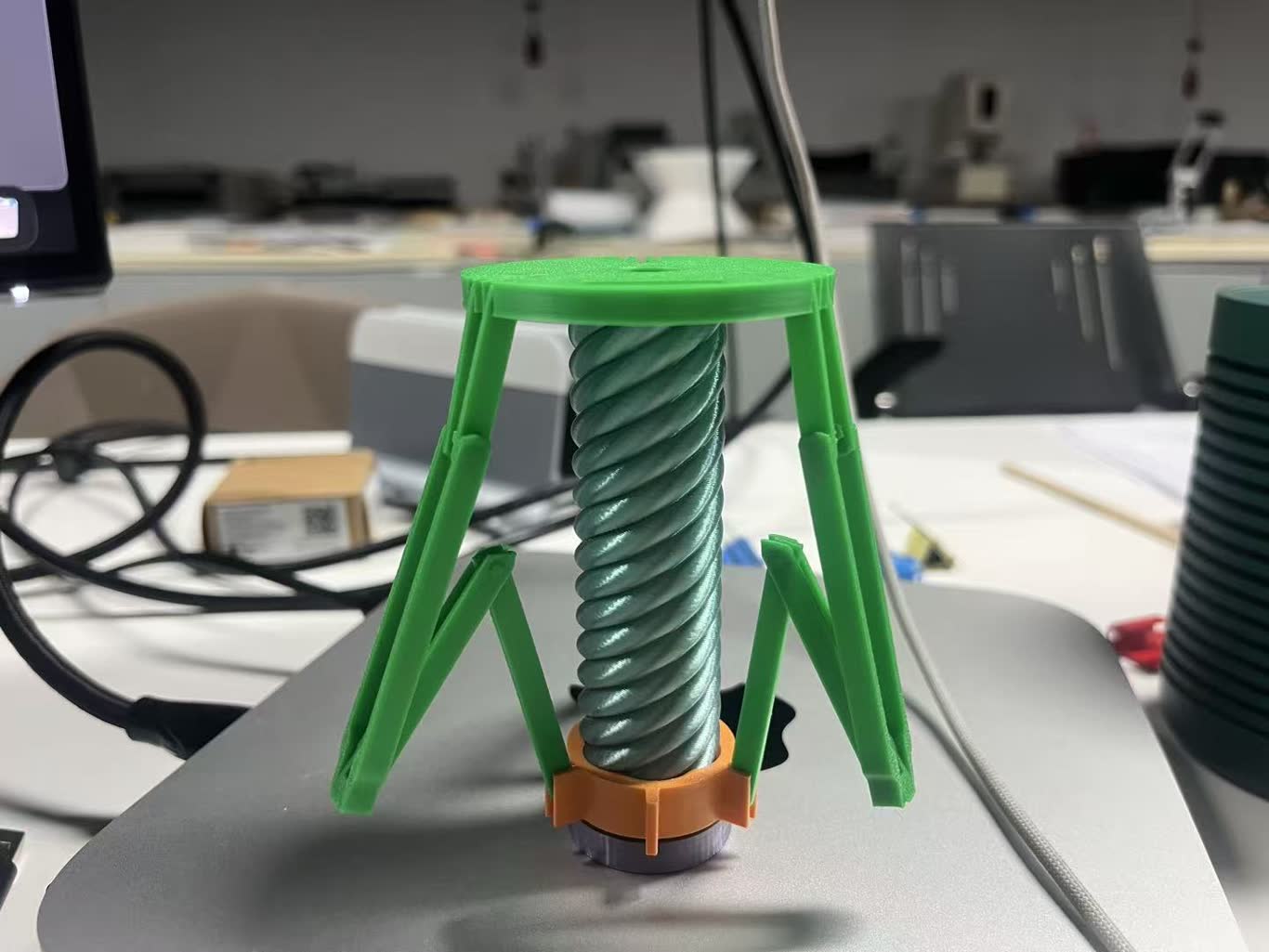
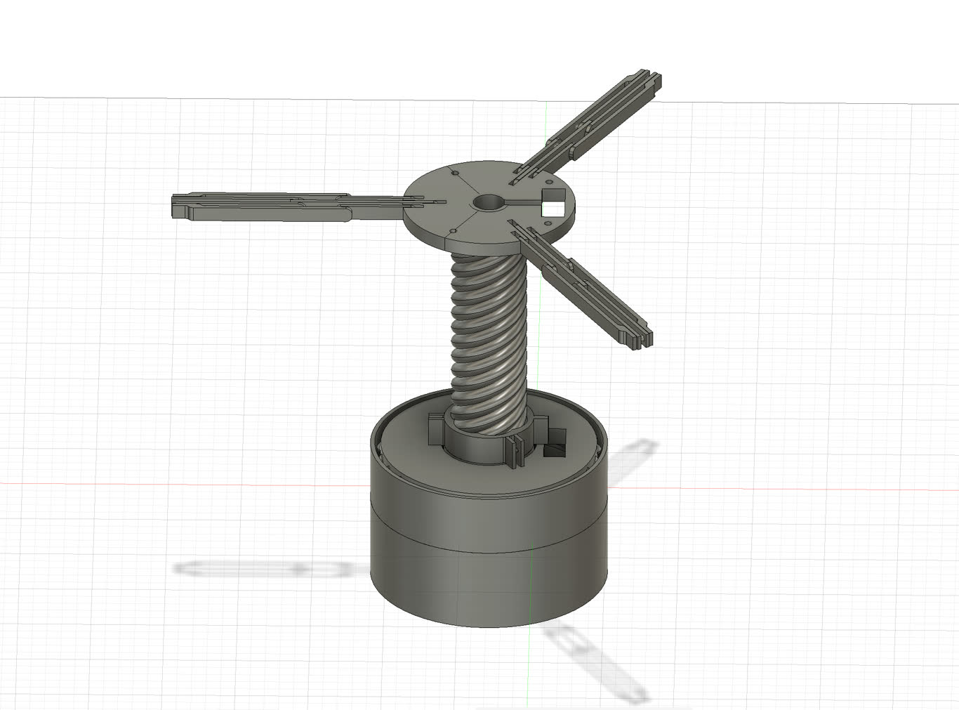
2026.5.18
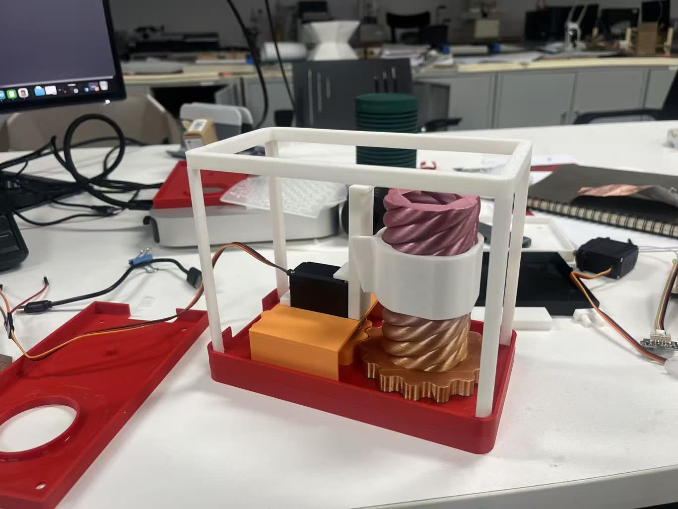
Then I update the structure and set a base to store PCB board and servo motor.
2026.5.19
Electrical Design
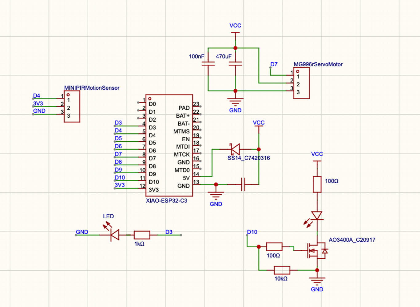
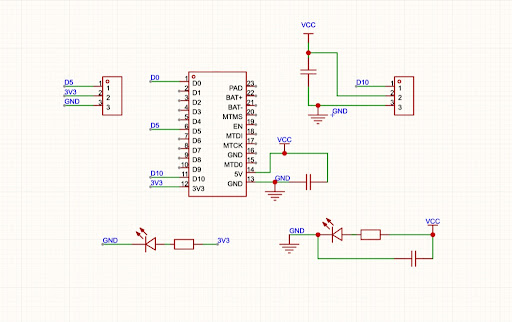 This is the intial version that I plan to use VCC to support Servo Motor which need a large voltage and current.
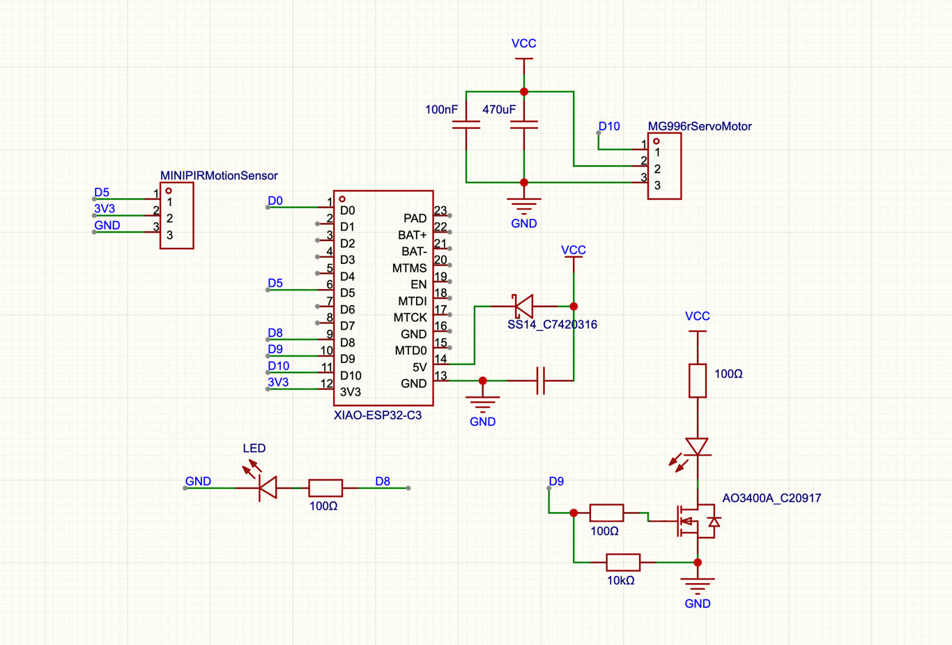
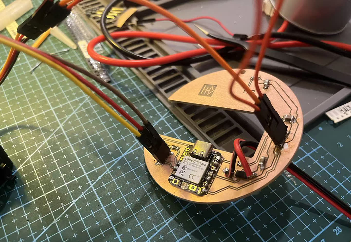
I use ESP32-C3 as a microcontroller, MG996r and LED light use 5V from VCC. PIR Motion senser, 1206 LED light use 3.3V from Xiao. However, the MG996R is a high-torque servo motor, with a very high working current (peak value can reach 1A - 2A), and additional capacitors need to be added. Add a switch for the LED lights and use an N-MOSFET.
MOFEST Learning
Metal Oxide Semiconductor Field Effect Transistor (MOSFET)
MOSFET Video animation MOSFET Drain (D) 漏极 MOSFET Source (S) 源极 MOSFET Gate (G) 栅极
The blocking diode is required. Without this diode having the USB C cable plugged in to charge/program while the battery is plugged in will at best destroy your battery and at worst light it on fire.
2026.5.23
After the modification, it is now like this, which has enhanced the reliability of the circuit.
2026.5.25
After talk with local instructor, she suggest me not to use GPIO2 / D0, GPIO8 / D8, and GPIO9 / D9, because when the ESP32-C3 is powered on or reset, it will first read the levels of several initialization pins. And also need to increase the width of the VCC line, as it needs to be at least 60 mils to handle the high current.
for Mos


2026.5.29
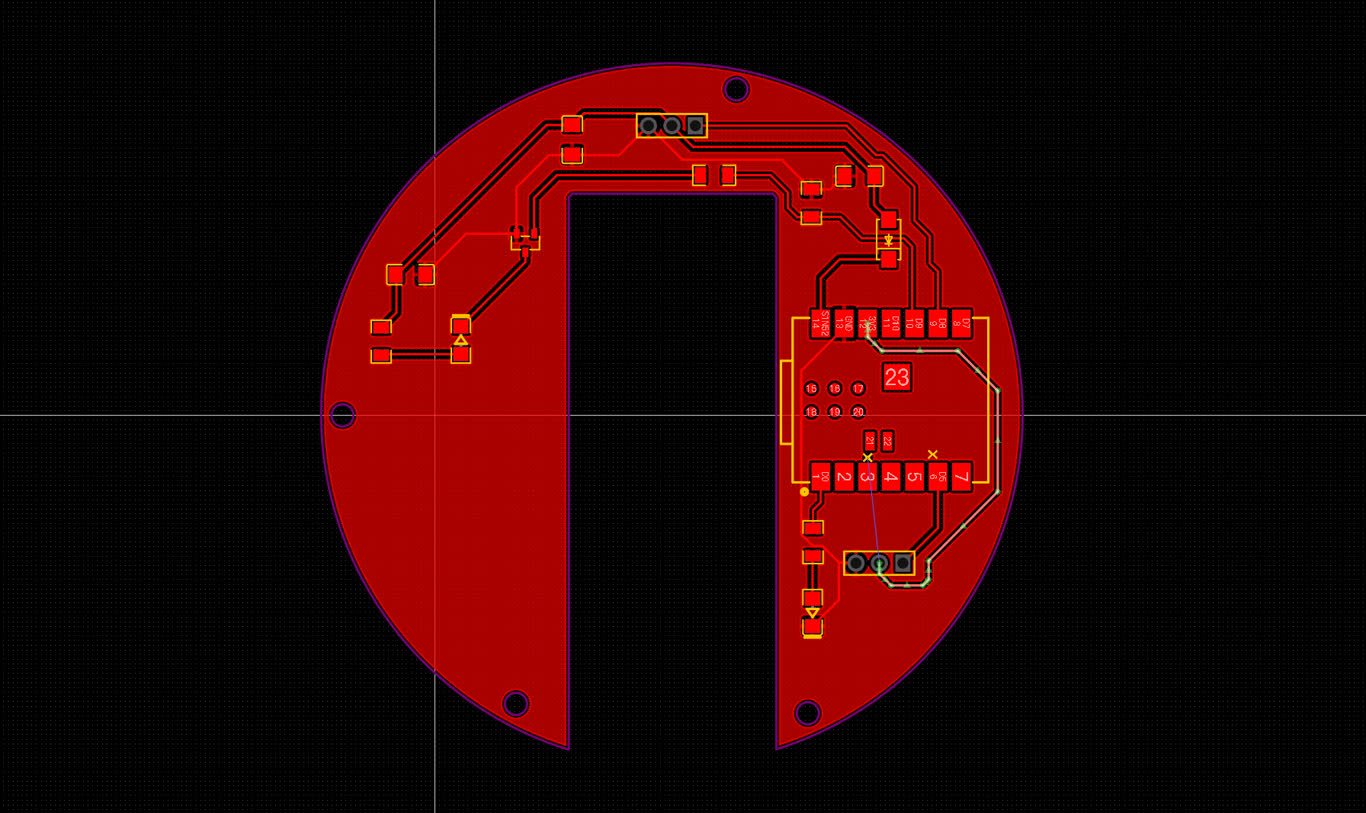
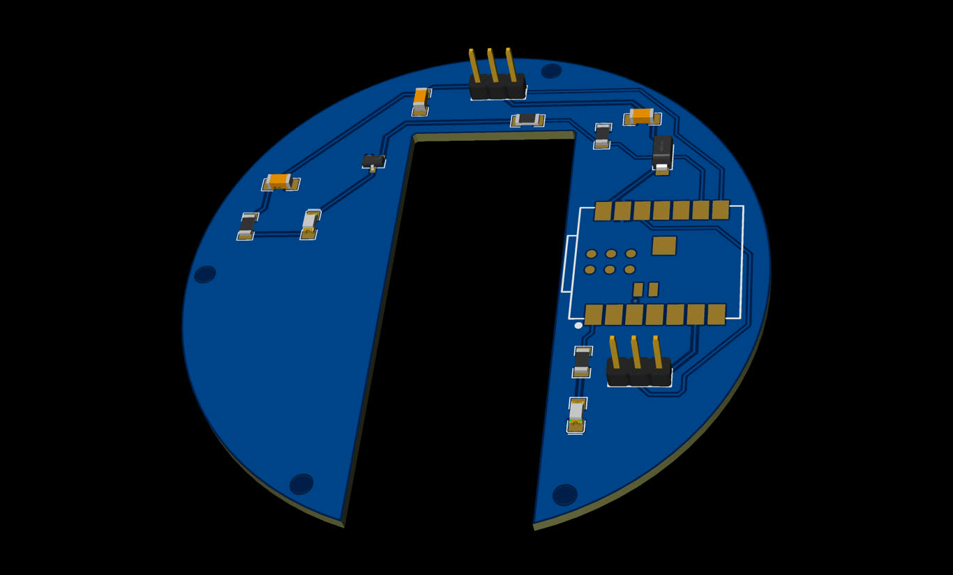
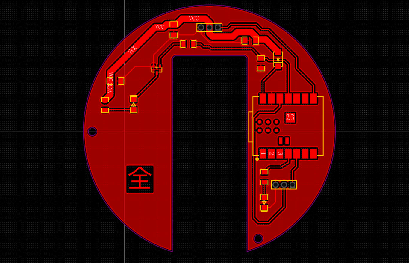
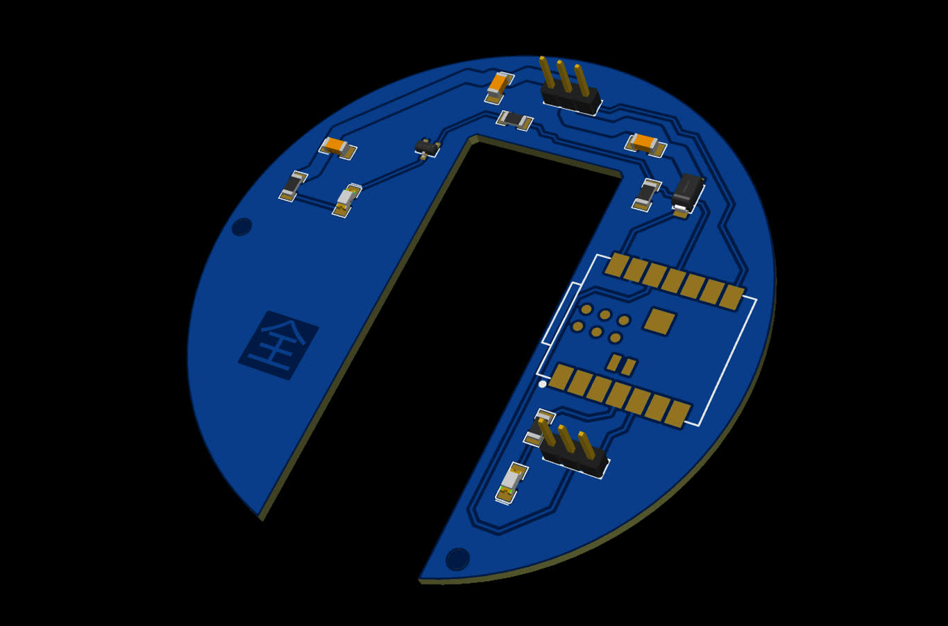
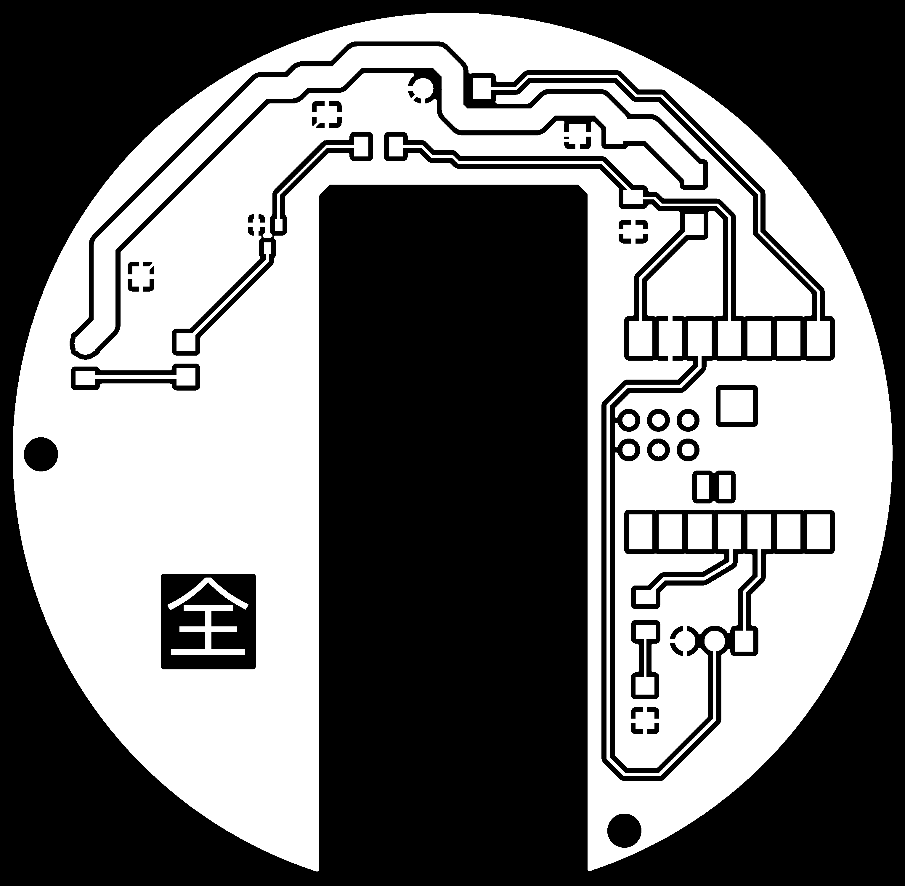
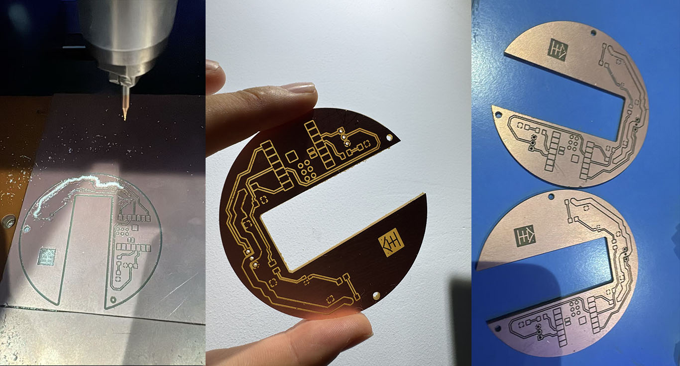
I got my own PCB board.
I am continues fail in making skin.
2026.5.30
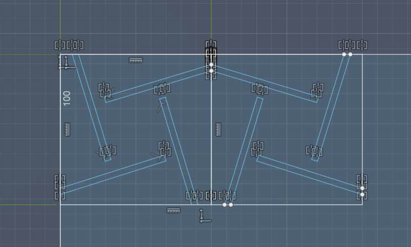
To extend the skin, I update the structure of linkage. I increase the contact area between skin and linkage, still its joint connection.
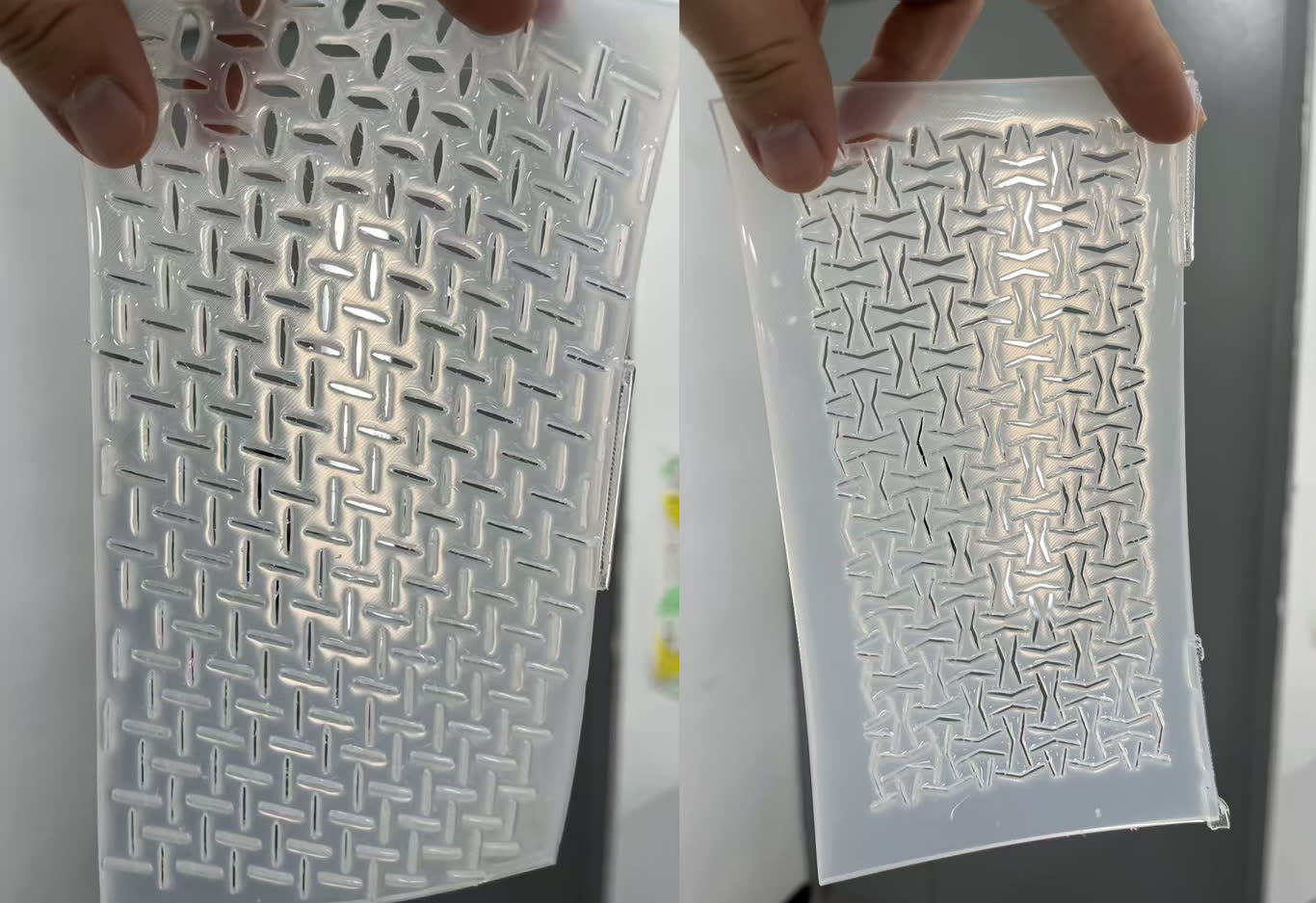
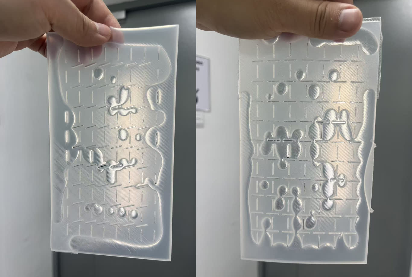
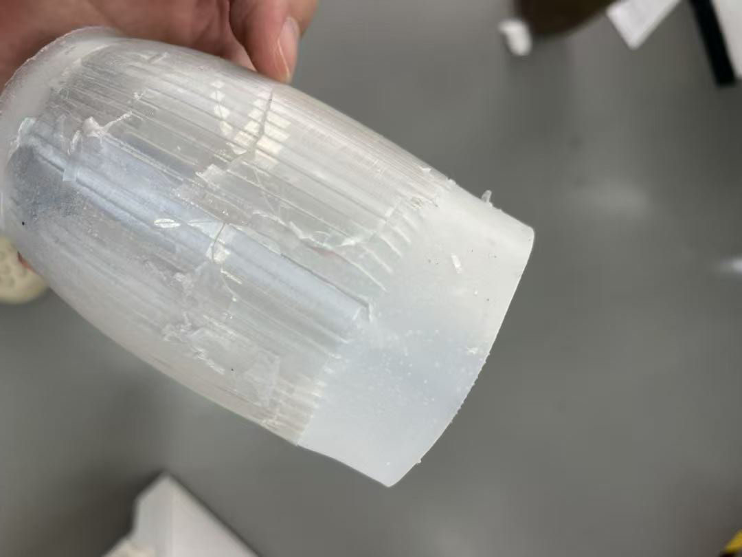
The mechanical structure is working, but I'm stuck on the skin fabrication. I tried casting it as a complete cylindrical lampshade, but the result only comes without the cutting pattern, which means I can't use it as a final product. The pattern is crucial because it enables the shape-changing function.
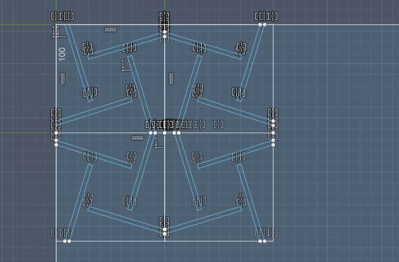
2026.6.01
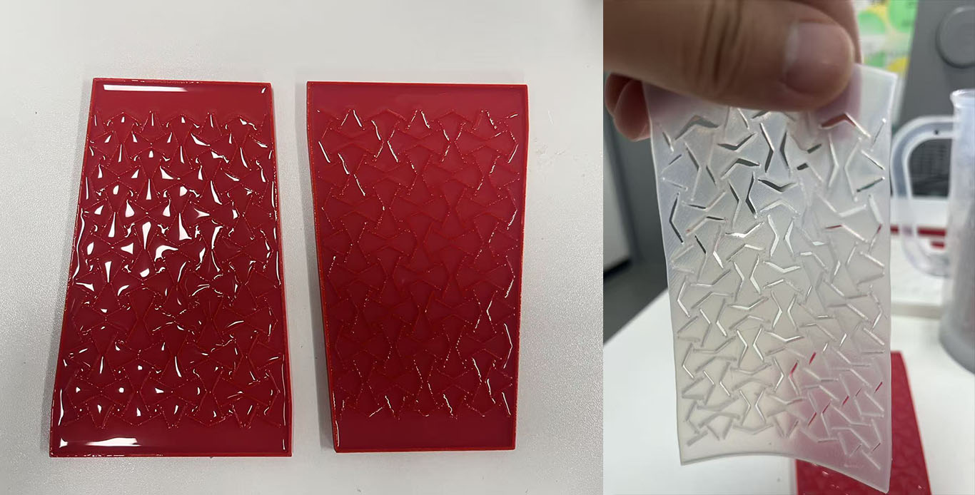
I have a new idea for making skin. Since casting it in one piece is difficult, I can try dividing it into three parts, each cast as a flat piece of skin.
2026.6.02
When soldering a PCB board, it's quite difficult to solder through holes from a single side. It's very easy to accidentally bridge the solder with nearby components, or fail to make a proper connection at all. There's no clear view of the joint and no convenient place to apply the solder. Maybe next time I'll avoid using through holes.
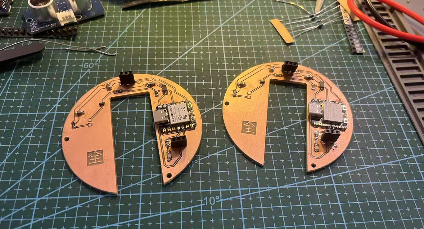
To check for short circuits, I have to frequently use a multimeter. Once a short occurs, I need to make adjustments. It really takes time.
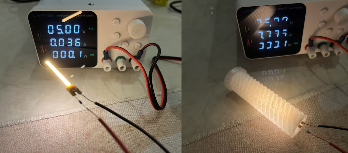
Tested the power supply and the LED lights. The overall appearance looks quite bright.
2026.6.04
I need to hurry up to test if the circuit works. Finally all soldering down, but still need to test.
2026.6.05
There are too many problems, the circuit doesn't work at all when connected, so I need to debug it.
Let me break down the task. I separate it into four steps:
- The LED lights up on the board.
- The LED powered by VCC needs to light up.
- The LED reacts to the PIR sensor.
- The PIR sensor triggers the LED and the servo motor.
Let's start with the simplest display LED. Why isn't it lighting up?
- after testing, I didn't solder the 3.3V pin well.
I switched to a 5V external power supply, but the XIAO ESP32-C3 wasn't receiving any power. Using a multimeter to test, I found the problem was the Schottky diode, it didn't achieve the desired effect and also blocked the current.
So I decided to remove it and create a jumper wire to directly connect the VCC 5V line.
It started working!!!!
However, this means I lose one layer of protection. I need to be careful not to use an external power source and the XIAO's USB at the same time, as this could damage the XIAO.
Why my The LED lights for lighting do not work
I connected to D10. Using a multimeter, I can see it generates regular LOW and HIGH signals, so the problem isn't the programming or the microcontroller. This time I used a MOSFET, so something might be wrong with it. My connections are correct, so the last possibility was the connection itself. Finally, the S pin to GND wasn't soldered well, so it wasn't connected.
Wow, it works!!!!
Then I changed to a smaller resistor, from 1kΩ to 50Ω, to make the LED brighter, which follows the datasheet from the supplier.
Why PIR motion sensor didn't work
I was connect on D4(GPIO6)
On the ESP32-C3, GPIO6 is a restricted pin. Connecting sensors and buttons and other external devices to it can easily cause problems.
Then I change to D2(GPIO4) it works!!.
Why Servo motor didn't work
I was using RP2040
Finally All DOWN, the The entire circuit succeed.
Some problem I need to refelect on schematic and update the PCB.
I have completed the design of the mechanical structure, packaging, as well as the design and production of the circuit board. Everything has been assembled and put together.
2026.06.06
I assemble all parts together. It looks pretty nice, but some gaps are too small, and hard to connect and hide wires. Right now it donen't have its skin, but I am happy it can work.
Following the experience, I enlarged some gaps to contain wires, making assembly easier.
2026.06.07
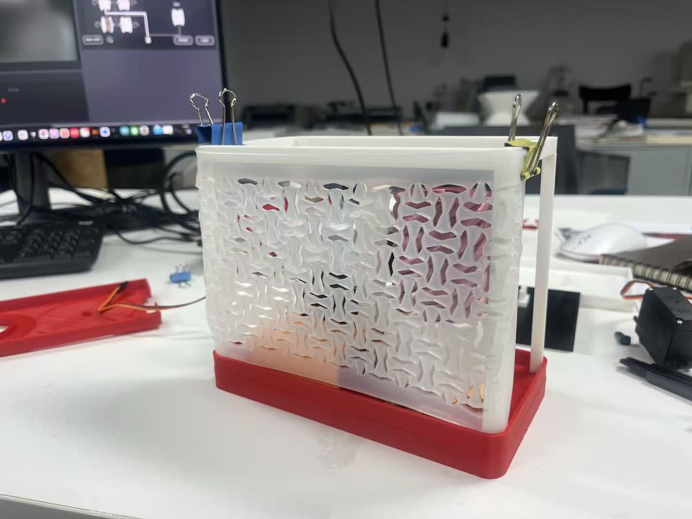
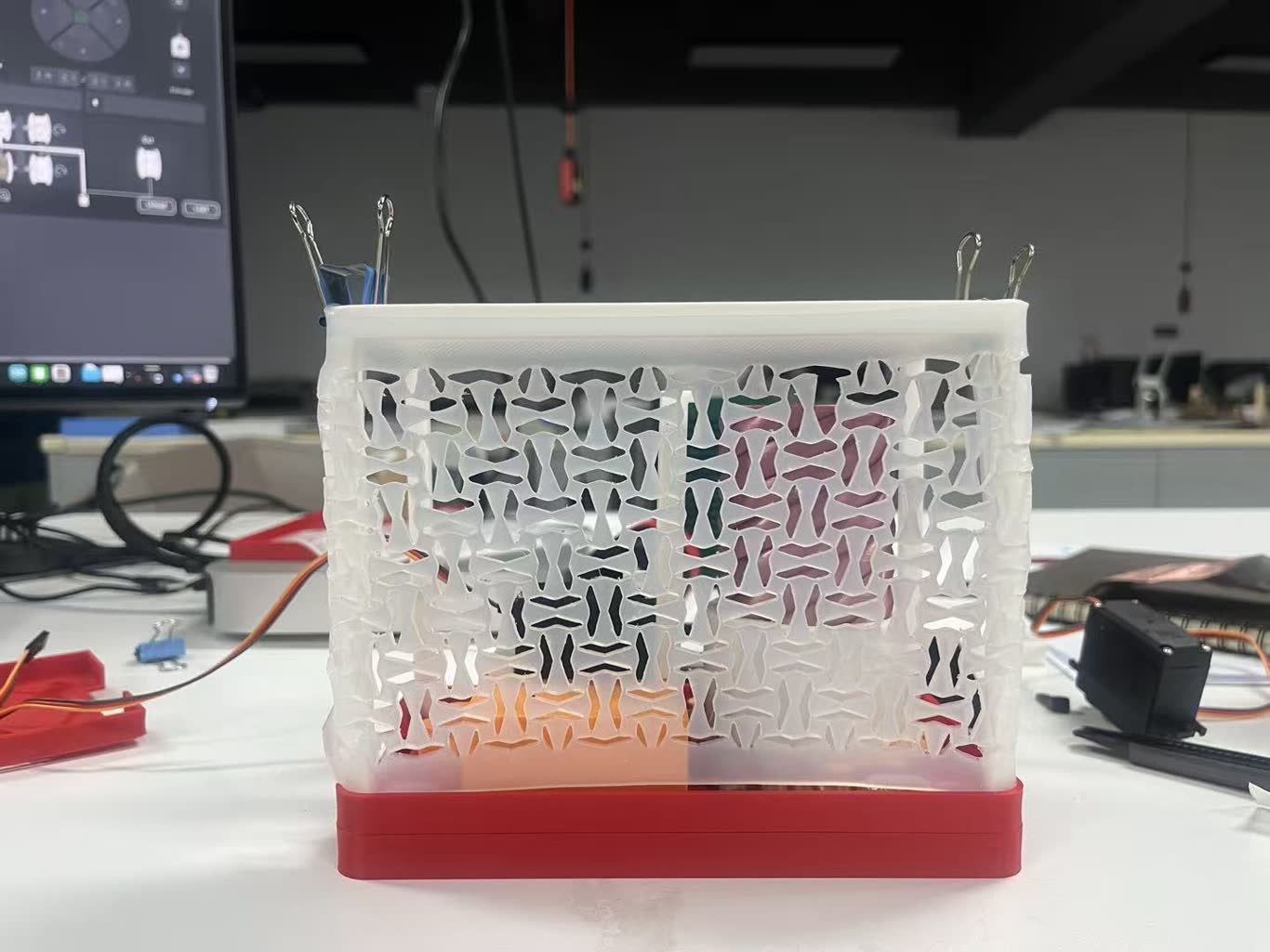
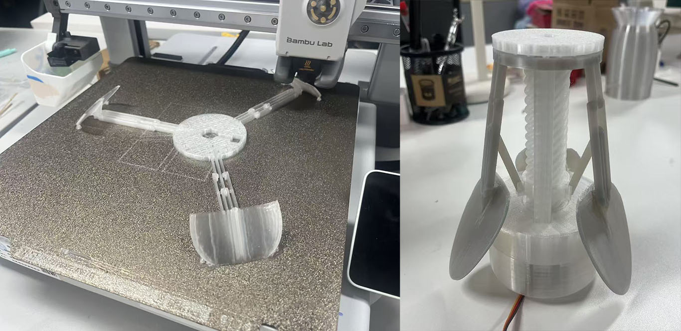
I assembled the skin onto the lamp. It tends to fall off easily, and the joints of the structure come apart from the twisting due to the elastic force of the skin.
Then I adjusted the 3D model to increase its strength and resist the elasticity. And 3D printing it.
I reassembled the skin with a strong structure. It worked, as I had thought before. The skin can be stretched when the twist lifts up.
2026.06.08
Slider making and video making