13 Mideterm review
- [x] post a system diagram for your project
- [x] list the tasks to be completed
- [x] make a schedule for doing them
- [x] schedule a meeting with your instructors for a graded review of these and your weekly assignments
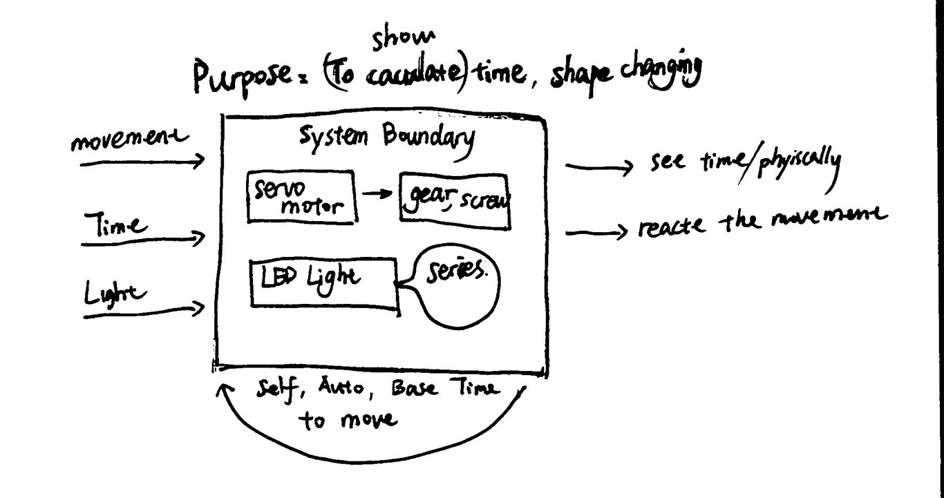
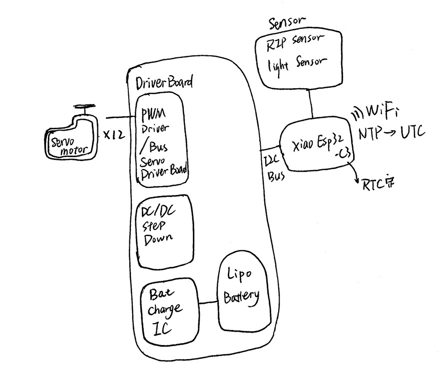
System Diagram
Microcontroller: ESP32
Input: Motion (RIP Sensor), Light Sensor, Colock Time
Output: Servo motor, LED light
3 Version Tasks
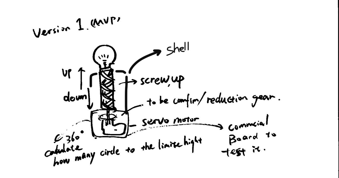
Version 1 "Exclamation Point" / 2026.5.10
Goal: When it senses movement of a person, the Exclamation Point light rises and the bulb lights up. When a person is not moving, the light off and lamp falls down.
Input
- Mini RIP Sensor x 1
Output
-
Servo motor MG90S x 1
-
LED light x 1
Electronical design
- ESP32-C3 x 1
Mechanical Design
-
3D print mechanical x 1
-
Shell x 1
Mechanical: Screw gear move up and down.
Electrical: Servo motor with gear to rotate.
Version 2 "Time wave"/ 2026.5.18
Goal: 6 servo motors connect together, every two hours (RTC)one light lamp up and the lampshade change its shape.
Input
-
Mini RIP Sensor x 1
-
Light Sensor x 1
Output
-
Servo motor MG90S x 6
-
LED light
Electronical design
- ESP32-C3 x 1
Mechanical Design
-
3D print mechanical x 6
-
Shell x 1
Molding and casting
- lampshade x 1
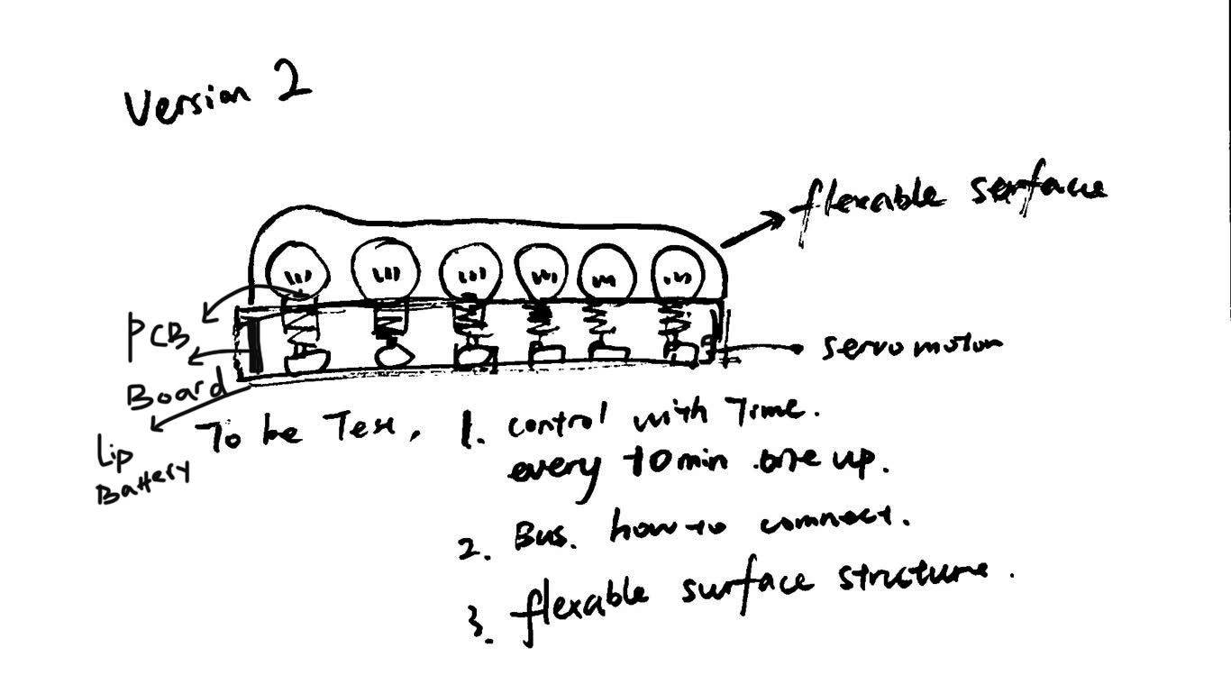
Mechanical: a row of screw gear move up and down.
Electrical: Servo motor with gear to rotate.
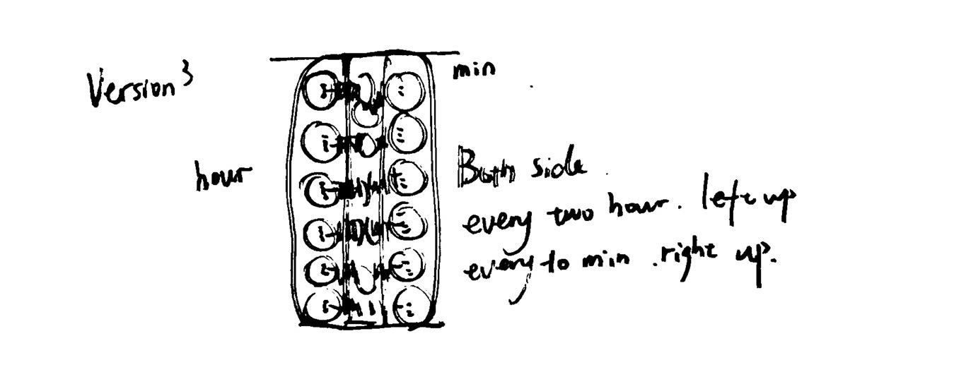
Version 3 "Wave reaction"/ 2026.5.31
Goal: 12 servo motors connect together, every two hours (RTC)one light lamp up and the lampshade change its shape. When it up it can create a sound base on the people reaction.
Input
-
Mini RIP Sensor x 1
-
Light Sensor x 1
Output
-
Servo motor MG90S x 12
-
LED light x 12
-
Speaker x 1
Electronical design
-
ESP32-C3 x 2
-
Bus driver x 1
Mechanical Design
-
3D print mechanical x 12
-
Shell x 1
Molding and casting
- lampshade x 2
GUI
- Screen on web control
Mechanical: two rows vertically of screw gear move up and down.
Electrical: Servo motor with gear to rotate.
Time management plan
Preparation
| Input | Output | Mechanical | electrnical | GUI | Network | Packing | |
|---|---|---|---|---|---|---|---|
| Version 1/"Exclamation Point" | RIP sensor | Servo motor | Twist gear | commercial board | - | - | 3D print |
| Version 2/"Time wave" | RCT/RIP sensor | Servo motor | Twist gear | PCB board/circuit design | - | Bus driver | 3D print/casting |
| Version 3/"Wave reaction" | RCT/RIP sensor | Servo motor | Twist gear | PCB board/circuit design | Web control | Bus driver | 3D print/casting |
Time schedule
2026.5.10 / Version 1
- 2026.5.4 / 3d design (mechanical design)
- 2026.5.6 / electronical design / mechanical prototype making
- 2026.5.8 / embeding programing
- 2026.5.10 / Version 1 demo
2026.5.18 / Version 2
- 2026.5.12 / 3d design (mechanical design)
- 2026.5.14 / surface design and prototype making
- 2026.5.16 / electronical design and embeding programing
- 2026.5.18 / Version 2 demo
2026.5.31 / Final version (Version 3)
- 2026.5.21 / 3d design (mechanical design)
- 2026.5.25 / electronical design and embeding programing
- 2025.5.28 / surface design and making
- 2026.5.30 / Final version testing
- 2026.5.31 / Video shooting