04 Embedded programming
Assignment
- Group assignment:
- Demonstrate and compare the toolchains and development workflows for available embedded architectures
- Document your work to the group work page and reflect on your individual page what you learned
- Individual assignment:
- Browse through the datasheet for a microcontroller
- Write and test a program for an embedded system using a microcontroller to interact (with local input &/or output devices) and communicate (with remote wired or wireless connections)
Overview:
This week's assignment has a relatively long span. I had some experience with the UNO board before, but not much. I hadn't studied data tables much before. Currently, I have two kits, the Seeed Studio XIAO Starter Kit and the DFRobot Gravity: Intermediate Kit for Arduino, as the main development boards for comparison. With a large amount of reading, I had to try using various AIs to assist with reading. For example, Kimi supports relatively long contexts, and MinMax has an image - recognition function. I also tried using AI Studio as a learning assistant. I have to say that learning now has a lot of support, and the daily learning volume doesn't require payment. Understanding in the early stage took quite some time, but I didn't encounter too many problems in practical operation. Of course, understanding the hardware is crucial. It let me know what kind of board to use under what circumstances, and it is quite helpful for my subsequent design of boards.
Product:
- Seeed Studio XIAO Starter Kit:https://www.seeedstudio.com/Seeed-XIAO-Starter-Kit-p-5378.html
Board: XIAO ESP32 C3/S3 | XIAO RP2040 | XIAO nRF52840
- DFRobot Gravity: Intermediate Kit for Arduino:https://www.dfrobot.com/product-1242.html
Board: UNO R3 (DFR0216)
| Board | Processor | Wireless | Best For |
|---|---|---|---|
| XIAO ESP32-C3 | RISC-V 160MHz, Powerful | Wi-Fi + Bluetooth | IoT Projects, Wireless |
| XIAO RP2040 | Dual-Core 133MHz, Parallel | None | Computing, Robotics, MicroPython |
| XIAO nRF52840 | Cortex-M4 64MHz, Ultra Low Power | Bluetooth + NFC | Wearables, Battery-Powered |
| UNO R3 | 8-bit 16MHz, Classic | None | Learning, Education |
Group assignment:
Datasheet compare
Because, comparatively speaking, the XIAO ESP32 S3 is a high - end version of the ESP32 C3. Therefore, we mainly use the data board of the ESP32 C3 to compare with other boards.
And I'm not very familiar with all the parameters of the development board. So I will make this part as detailed as possible, to the extent that beginners can understand.
Parameter Explanation
| Parameter | What Does It Mean? | Bigger = Better? |
|---|---|---|
| Processor | The "brain" of the board, determines speed | ✅ Higher MHz = Faster |
| SRAM | Working memory, lost when power off | ✅ Larger = Complex programs |
| Flash | Storage for programs, kept when power off | ✅ Larger = Bigger programs |
| Digital I/O | Connect LEDs, buttons, etc. | Just needs to be enough |
| Analog Input | Connect sensors like light/temp | Just needs to be enough |
| Wi-Fi/Bluetooth | Wireless communication | Choose as needed |
Specifications Table
| Specification | ESP32-C3 | RP2040 | nRF52840 | UNO R3 |
|---|---|---|---|---|
| Processor | RISC-V 160MHz | Dual-Core M0+ 133MHz | Cortex-M4 64MHz | 8-bit 16MHz |
| SRAM | 400KB | 264KB | 256KB | 2KB |
| Flash | 4MB | 2MB | 2MB | 32KB |
| Digital I/O | 11 (all PWM) | 11 (all PWM) | 11 (all PWM) | 14 (6 PWM) |
| Analog Input | 4ch | 4ch | 6ch | 6ch |
| Wi-Fi | 802.11 b/g/n | ❌ | ❌ | ❌ |
| Bluetooth | BLE 5.0 | ❌ | BLE 5.0 | ❌ |
| NFC | ❌ | ❌ | ✅ | ❌ |
| Size | 21×17.8mm | 21×17.8mm | 21×17.8mm | 75×54mm |
| Voltage | 3.3V | 3.3V | 3.3V | 5V |
| Price | $4-5 | $4-5 | $10-16 | $8-12 |
Selection Guide
- ✅ Need Wi-Fi/Bluetooth → ESP32-C3
- ✅ Need High Performance (Dual-Core) → RP2040
- ✅ Need Ultra Low Power/NFC → nRF52840
- ✅ Complete Beginner → UNO R3 (Most tutorials)
Power Consumption Comparison
Tip: Lower sleep power = longer battery life
| Board | Deep Sleep | Active Power | Battery Charging | Best For |
|---|---|---|---|---|
| ESP32-C3 | ~44 μA | 40-80mA | Yes (350mA) | Li-po battery, Mains power |
| RP2040 | ~1.9 μA | 20-40mA | ❌ | Short-term projects |
| nRF52840 | <5 μA | 5-15mA | Yes (100mA) | Coin battery, Long-term |
| UNO R3 | ❌ | 30-50mA | ❌ | Mains powered |
Summary: nRF52840 has the lowest power consumption ideal for long-term battery-powered devices, ESP32-C3 supports fast charging suitable for mobile use, UNO R3 does not support deep sleep and is best for mains-powered applications.
Pinout Diagrams
ESP32-C3 Pinout
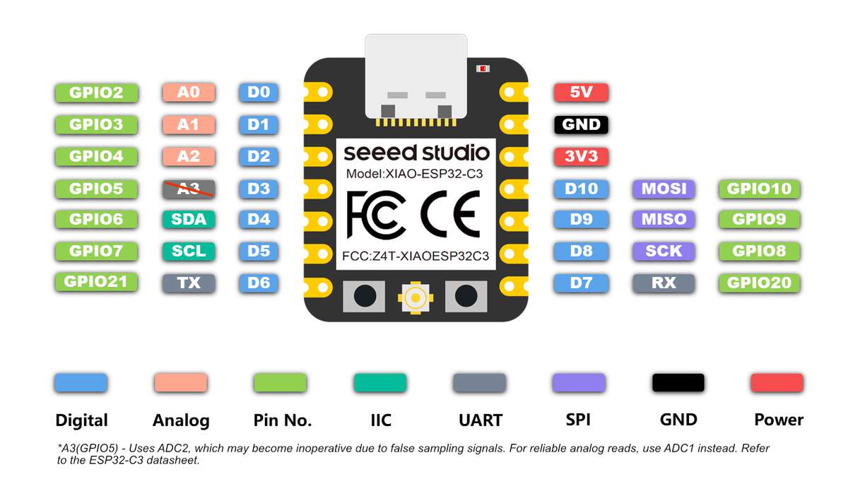
| Pin | Function | Common Use |
|---|---|---|
| D0-D3 | GPIO/ADC | Digital I/O, Analog sensors |
| D4-D5 | I2C | OLED, Temp/Humidity sensors |
| D6-D7 | UART | Serial debug, GPS module |
| D8-D10 | SPI | SD card, Display |
| 3V3 | Power Output | 500mA max |
Summary: ESP32-C3 uses D4/D5 for I2C, D6/D7 for UART, D8-D10 for SPI, and all pins support PWM.
RP2040 Pinout
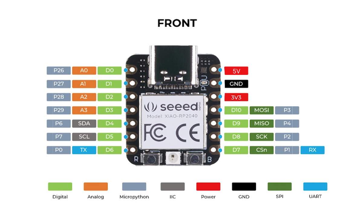
| Pin | Function | Common Use |
|---|---|---|
| D0-D3 | ADC | 4ch Analog input |
| D4-D5 | I2C | Default I2C pins |
| D6-D7 | UART | Serial communication |
Summary: RP2040 uses D4/D5 as default I2C pins, D6/D7 for UART, and D0-D3 support 4-channel ADC analog input.
nRF52840 Pinout
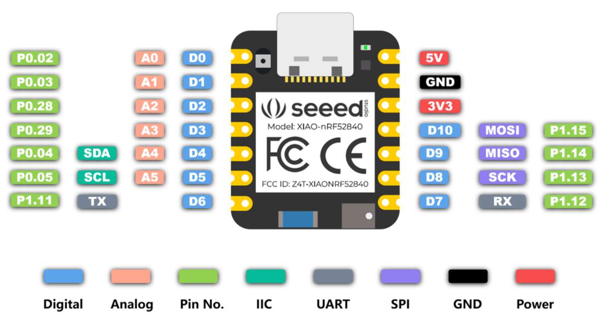
Pin Functions
| Pin | Function | Common Use |
|---|---|---|
| D0-D3 | ADC | 4ch Analog input |
| D4-D5 | I2C | Default I2C pins |
| D6-D7 | UART | Serial communication |
Summary: nRF52840 supports 6-channel analog input, D4/D5 can be used for I2C, and includes NFC functionality.
UNO R3 Pinout
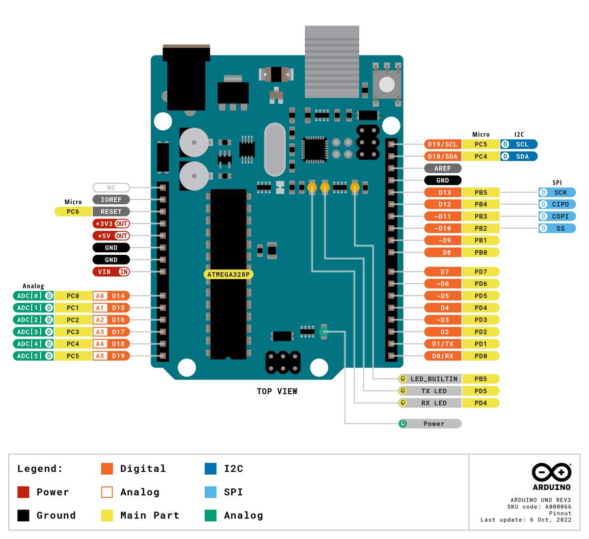
| Pin | Function | Common Use |
|---|---|---|
| D0-D13 | Digital I/O | 14 pins, 6 PWM |
| A0-A5 | Analog Input | 10-bit ADC |
| A4/A5 | I2C | SDA/SCL |
Summary: UNO R3 has 14 digital pins (6 support PWM), 6 analog pins, and A4/A5 can be used for I2C.
Official Resources
| Resource | Link |
|---|---|
| ESP32-C3 Getting Started | https://wiki.seeedstudio.com/XIAO_ESP32C3_Getting_Started/ |
| RP2040 Getting Started | https://wiki.seeedstudio.com/XIAO-RP2040/ |
| nRF52840 Getting Started | https://wiki.seeedstudio.com/XIAO_BLE/ |
| Arduino UNO R3 Docs | https://docs.arduino.cc/hardware/uno-rev3/ |
Individual assignment:
Arduino IDE
- Official Download : arduino.cc/en/software
- Documentation & Tutorials : docs.arduino.cc/software/ide/
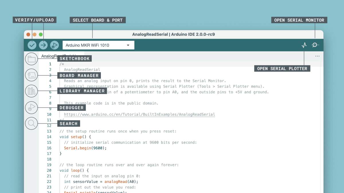
Arduino IDE Operation Guide
1. Initialization
- Launch IDE: Open the Arduino IDE application.
- Create New Sketch: Click File → New. This generates a template with the mandatory
setup()andloop()functions.
2. Hardware Setup
- Connect Board: Use a USB cable to connect your Arduino board to the computer.
- Select Board Type: Click Tools → Board. Choose your specific model (e.g., Arduino Uno) from the list.
- Select Serial Port: Click Tools → Port. Select the active port (usually
COMxon Windows or/dev/tty.usb...on macOS/Linux).
3. Development
- Write/Edit Code: Input your logic in the main editor window.
- Manage Libraries: If the project requires sensors or displays, go to Tools → Library Manager to search and install third-party drivers.
4. Compilation & Deployment
- Verify/Compile: Click the Checkmark (✅) icon in the toolbar or Sketch → Verify/Compile.
- Result: Check the console at the bottom for "Done compiling" to ensure there are no syntax errors.
- Upload: Click the Right Arrow (➡️) icon or Sketch → Upload.
- Result: Wait for "Done uploading" to appear, indicating the code is running on the board.
5. Debugging
- Serial Monitor: Click the Magnifying Glass (🔍) icon or Tools → Serial Monitor.
- Crucial Step: Match the Baud Rate in the monitor with the
Serial.begin()value in your code (e.g.,9600or115200).
Important Notes
- Driver Requirements: If the "Port" is greyed out, you likely need to install USB-to-Serial drivers (e.g., CH340, CP210x, or FTDI).
- Workflow Logic: Always Verify first to catch errors before attempting an Upload to save time.
- Library Dependencies: For complex components, you must install the corresponding library via the Library Manager first.
- Power Supply: High-power components (motors, relays) require an external power source; USB power alone may cause the board to reset.
Individual assignment:
DFRobot UNO R3
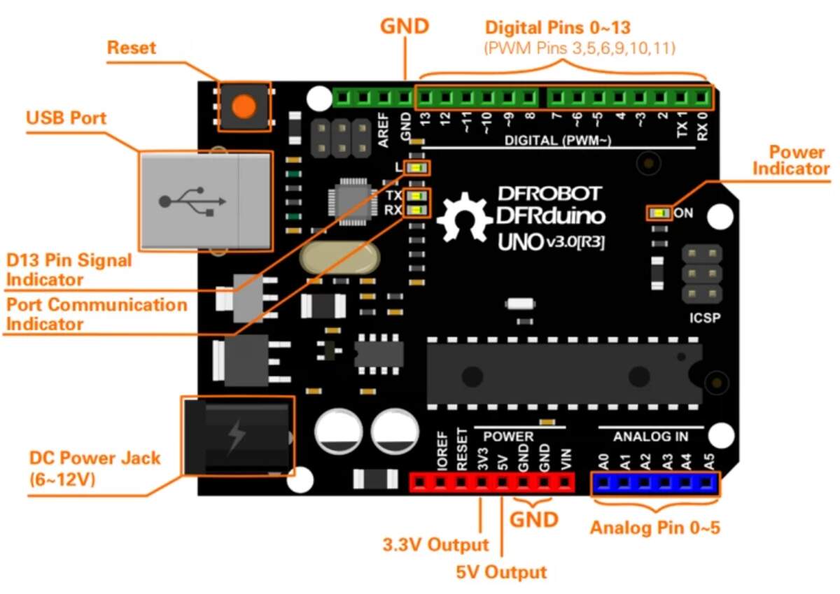
As a beginner in embedded development, the journey starts with recognizing the hardware. The DFRduino UNO R3 is an ideal entry-level board for several reasons:
-
Novice Friendly: It is the most popular open-source hardware platform with a vast array of tutorials.
-
Pinout & Accessibility: The board provides clear access to Digital and Analogue pins.
Technical Specifications
| Parameters | Specifications |
|---|---|
| Microcontroller (MCU) | ATmega328P (8-bit AVR Architecture) |
| Operating Voltage | 5V |
| Digital I/O Pins | 14 (6 support PWM output) |
| Analog Input Pins | 6 (10-bit ADC) |
| Serial Communication | 1 Channel (UART: Pin 0-RX, Pin 1-TX) |
| External Interrupts | 2 Channels (D2, D3) |
System Design & Materials
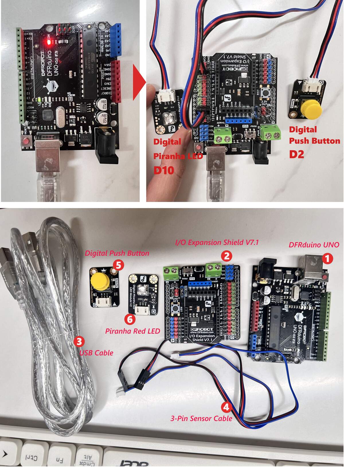 Overview of the final assembly and all required components.
Bill of Materials (BOM)
| No. | Component | Qty | Function |
|---|---|---|---|
| ① | DFRduino UNO | 1 | Main microcontroller board |
| ② | IO Shield V7.1 | 1 | Interface expansion board |
| ③ | USB Cable | 1 | Programming and power supply |
| ④ | 3-Pin Sensor Cable | 2 | Easy-to-install Gravity connection cables |
| ⑤ | Push Button | 1 | Input device (Connected to D2) |
| ⑥ | Piranha LED | 1 | Output device (Connected to D10) |
Expansion Shield V7.1
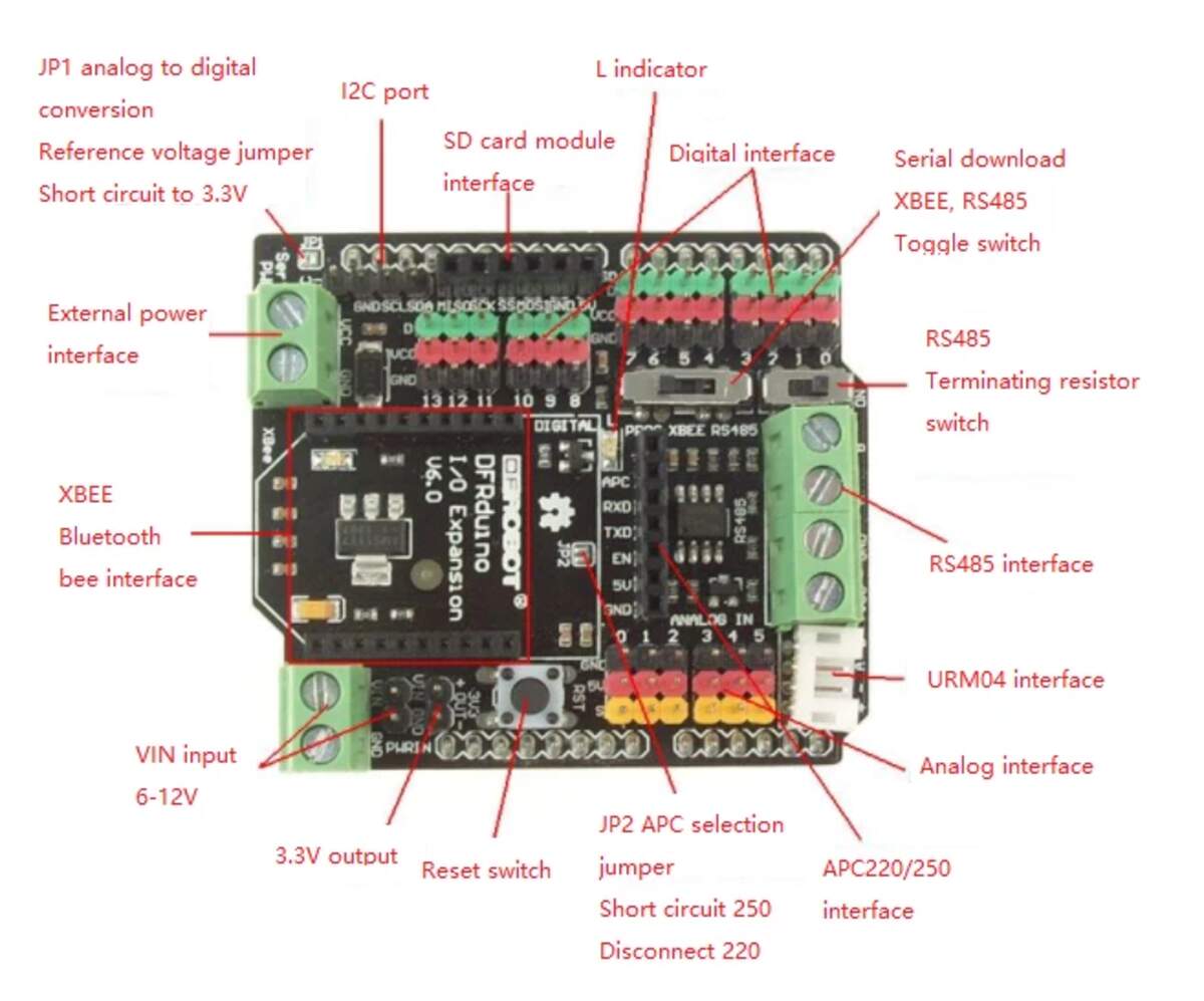
| Feature | Technical Details |
|---|---|
| Color Coding | Green: Digital; Blue: Analog; Red: VCC; Black: GND. |
| RUN/PROG Switch | Set to PROG when uploading code with wireless modules attached. |
| Voltage Support | 3.3V/5V switchable output for different logic levels. |
| Interfaces | Dedicated slots for I2C, UART, SD Card, and XBee modules. |
Component Selection & Logic
- Input (D2): Digital Push Button — Sends a HIGH/LOW digital signal to the controller when pressed.
- Output (D10): Digital Piranha LED — Lights up when receiving a HIGH signal from the controller.
Assembly Instructions
- Step 1: Mount the IO Shield onto the UNO board, ensuring all pins are fully inserted.
- Step 2: Connect the Button to D2 and the LED to D10 using the 3-pin sensor cables.
- Step 3: Plug in the USB cable; the onboard Power LED will light up immediately, indicating the system is active.
⚠️ Caution: - Match Colors: Ensure cable colors match pin colors (Green-Blue/Red/Black) to prevent short circuits. - Check Switch: Ensure the RUN/PROG switch is on RUN for normal operation.
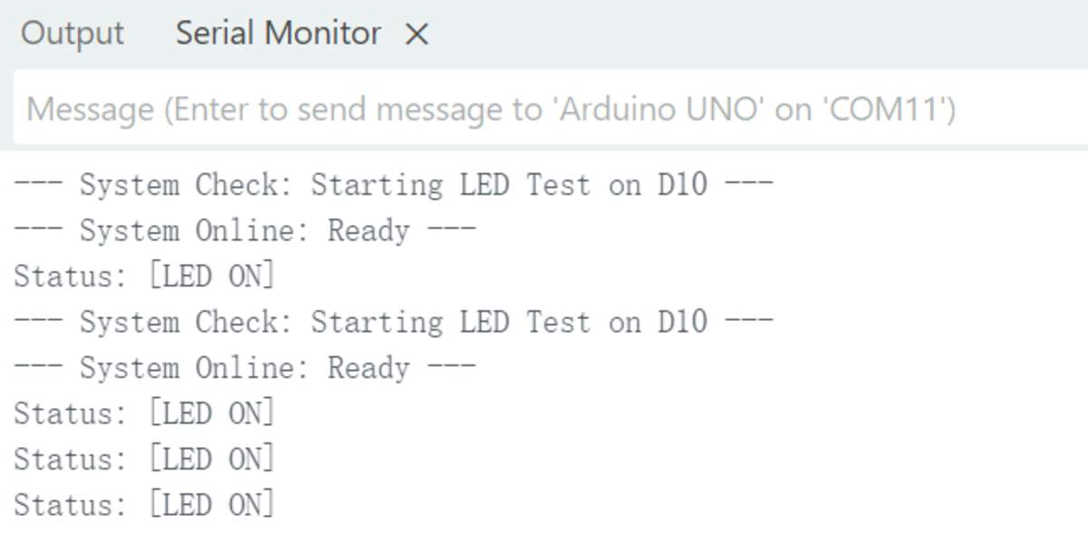
Programming & Logic Implementation
Logic Flow
The system execution is divided into two phases: 1. Hardware Self-Test Phase: This feature was added after encountering a situation where the LED failed to light up. After discussing with Gemini AI, I decided to implement a startup test where the LED on D10 flashes 3 times immediately after power-up. This ensures that the wiring and LED module are 100% functional before entering the main loop. 2. Main Interaction Phase: The system continuously polls the state of the D2 pin. When a HIGH signal is detected (button pressed), it drives the D10 pin to light up the Piranha LED and sends a status string to the PC via the Serial port.
// 1. Pin Definitions
const int BUTTON_PIN = 2; // Button connected to D2
const int LED_PIN = 10;    // Migrated to D10 to avoid interference with the onboard D13 LED
void setup() {
  // 2. Initialize Serial communication at 9600 bps
  Serial.begin(9600);

  // 3. Configure pin modes
  pinMode(BUTTON_PIN, INPUT);  // Read button state
  pinMode(LED_PIN, OUTPUT);    // Drive Piranha LED

  Serial.println("--- System Check: Starting LED Test on D10 ---");
  // 4. Hardware Self-Test (Debug logic added after discussion with Gemini)
  // If the external LED doesn't blink here, the issue is hardware-related (wiring/polarity).
  for(int i = 0; i < 3; i++) {
    digitalWrite(LED_PIN, HIGH);
    delay(200);
    digitalWrite(LED_PIN, LOW);
    delay(200);
  }
  Serial.println("--- System Online: Ready ---");
}
void loop() {
  // 5. Read the digital signal from the button
  int buttonStatus = digitalRead(BUTTON_PIN);
  // 6. Logic to control LED based on input
  if (buttonStatus == HIGH) {
    // Button pressed
    digitalWrite(LED_PIN, HIGH);
    Serial.println("Status: [BUTTON PRESSED] -> LED ON");
  } else {
    // Button released
    digitalWrite(LED_PIN, LOW);
  }

  delay(50); // Stability delay
}
Essential Structure
-
void setup(): Runs once at startup. Used to initialize pins and communication.
-
void loop(): Runs repeatedly. This is where the main interaction logic lives.
Key Commands
-
pinMode(pin, mode): Configures a pin as INPUT (sensor) or OUTPUT (LED).
-
digitalRead(pin): Checks if a pin is HIGH (5V/Pressed) or LOW (0V/Released).
-
digitalWrite(pin, level): Sends a HIGH (On) or LOW (Off) signal to a pin.
-
Serial.begin(9600): Starts communication with the computer at 9600 bits per second (baud rate) to establish a bridge for real-time monitoring.
-
Serial.println(): Logs status messages to the Serial Monitor. The output "--- System Online: Ready ---" confirms the system has bypassed the self-test and is ready.
-
delay(ms): Pauses the program for a set number of milliseconds for signal stability.
Logic & Syntax
-
if-else: The decision-making block that executes code based on the button state (Input-Logic-Output pattern).
-
Semicolon (;): Every instruction must end with a
;. Missing this is a common cause of "Compile Errors." -
Comments (//): Text after
//is ignored by the board; used for human notes. -
Curly Braces ({ }): Used to group blocks of code together.
-
Pin Migration: Abandoning D13 for D10 avoids signal interference from the onboard "L" LED circuit during initialization.
Testing & Debugging (AI-Assisted)
During development, Gemini AI helped resolve several technical hurdles:
-
Syntax Error: - Problem: Copied ```cpp markers into the IDE, causing "stray" character errors.
-
Solution: AI identified formatting markers; removing them fixed compilation.
-
Sync Error: - Problem:
not in sync: resp=0x00upload failure. -
Solution: AI suggested verifying the COM port; reselecting the correct port in the IDE solved it.
-
Polarity Issue: - Problem: Serial active but LED stayed off.
-
Solution: AI suggested checking header orientation; swapping the 3-pin connector orientation fixed the reversed polarity.
## Seeed Studio XIAO ESP32-C3
Official Wiki | Expansion Board Wiki
The XIAO ESP32-C3 is a thumb-sized, high-performance, low-power IoT development board. It is based on the RISC-V architecture and comes with integrated Wi-Fi and Bluetooth 5.0 (BLE). It is the perfect "next step" for beginners who want to move from the basic Arduino UNO to advanced wireless and wearable projects.
Hardware Overview & Pinout
Understanding the physical layout is the first step to avoiding hardware damage.
XIAO ESP32-C3 Layout
- Front Side: Contains the ESP32-C3 SoC (System on Chip) under the metal shield, the USB-C port for programming/power, an IPEX antenna connector for Wi-Fi, and two tiny buttons: BOOT and RESET.
- Back Side: Features clear labels for the 11 GPIO pins and two battery pads (BAT+ and BAT-) for connecting a 3.7V Lithium battery.
![[xiaoc3.jpg]](../04Embedded-programming/xiaoc3.jpg) XIAO Expansion Board
To avoid complex breadboard wiring, we use the dedicated Expansion Board. It integrates:
- 0.96" OLED Screen: Connected via I2C (Pins D4/D5).
- User Button: Connected to Pin D1.
- Buzzer: Connected to Pin D3.
- Grove Connectors: For easy "plug-and-play" with sensors.
XIAO Expansion Board
To avoid complex breadboard wiring, we use the dedicated Expansion Board. It integrates:
- 0.96" OLED Screen: Connected via I2C (Pins D4/D5).
- User Button: Connected to Pin D1.
- Buzzer: Connected to Pin D3.
- Grove Connectors: For easy "plug-and-play" with sensors.
![[xiaoex.jpg]](../04Embedded-programming/xiaoex.jpg)
System & Environment Configuration
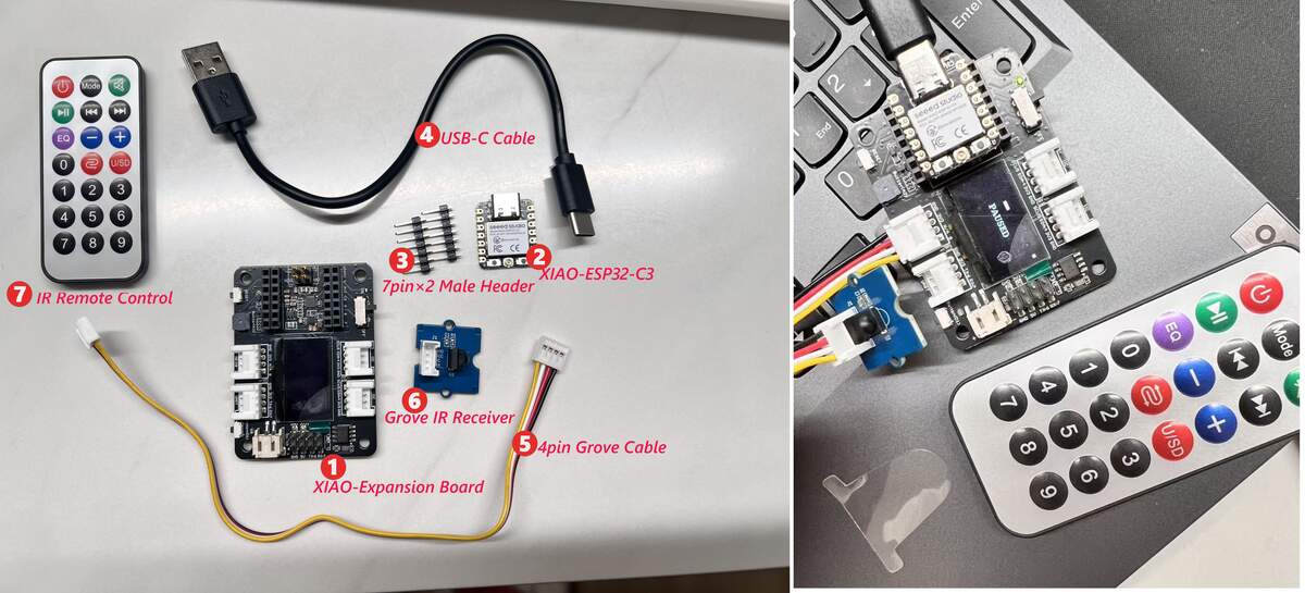 Left: All experimental materials (No. 1-7); Right: Assembled state connected to a laptop.
Bill of Materials (BOM)
| No. | Component | Qty | Function |
|---|---|---|---|
| ① | XIAO Expansion Board | 1 | Provides OLED display, Grove ports, and battery management. |
| ② | XIAO-ESP32-C3 | 1 | Main controller with Wi-Fi/BLE for logic processing. |
| ③ | 7-pin Male Headers | 2 | Used to mount the ESP32-C3 module onto the expansion board. |
| ④ | USB-C Cable | 1 | Used for programming and power supply. |
| ⑤ | 4-pin Grove Cable | 1 | Easy and fast connection for sensor modules (Anti-reverse). |
| ⑥ | Grove IR Receiver | 1 | Receives infrared signals from the remote control. |
| ⑦ | IR Remote Control | 1 | Input device for sending remote commands. |
Component Selection & Logic
- Input Device: IR Remote Control (⑦) sends commands via the IR Receiver (⑥). The receiver is connected to the Grove port on the expansion board.
- Output Device: OLED Display (integrated on Expansion Board ①), used to display received IR codes or system status in real-time.
Assembly Instructions
- Step 1: Mount the XIAO-ESP32-C3 module onto the expansion board using the headers, ensuring correct orientation.
- Step 2: Connect the IR Receiver to the expansion board's Grove port (A0-D0 or designated port) using the Grove cable.
- Step 3: Connect the system to your computer using the USB-C cable.
- Status Feedback: The OLED screen lights up, indicating the system is powered on and ready for debugging.
⚠️ Caution: - Connection Check: Grove cables are keyed; do not force the connection if it doesn't slide in easily. - Remote Battery: Ensure the battery is installed and the plastic insulation tab is removed before use.
Problem: Slow Downloads in China By default, the Arduino IDE downloads board packages from GitHub. In China, this is often extremely slow or results in a "Timed Out" error.
Solution: Using the Jihulab Mirror We use a high-speed mirror provided by Jihulab to download the ESP32 core files instantly.
- Open Arduino IDE, go to
File > Preferences. - In the "Additional Boards Manager URLs" field, paste this mirror link:
https://jihulab.com/esp-mirror/espressif/arduino-esp32/-/raw/gh-pages/package_esp32_index.json - Go to
Tools > Board > Boards Manager..., search for "esp32", and click Install. - Once installed, select your board:
Tools > Board > ESP32 Arduino > XIAO_ESP32C3.
Required Libraries (Git Links) You must install these two libraries to control the screen and the remote: 1. U8g2 Library: https://github.com/olikraus/u8g2 (For the OLED Display). 2. IRremote Library: https://github.com/Arduino-IRremote/Arduino-IRremote (For Infrared signals).
Programming Phases & Detailed Logic
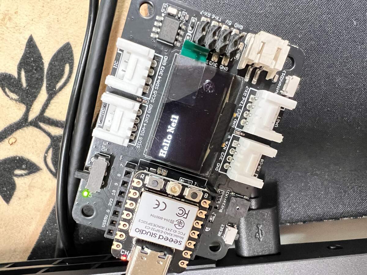
Phase 1: OLED Display Test ("Hello Neil")
Goal: Ensure the XIAO C3 can talk to the screen via the I2C protocol.
#include <U8g2lib.h> // Include the graphics library
#include <Wire.h>    // Include I2C communication library

// Constructor: This line tells the code exactly which screen we are using.
// SSD1306 is the driver chip, 128x64 is the resolution.
U8G2_SSD1306_128X64_NONAME_F_HW_I2C u8g2(U8G2_R0, /* reset=*/ U8X8_PIN_NONE);

void setup() {
  u8g2.begin(); // Start the OLED screen
}

void loop() {
  u8g2.clearBuffer();                   // 1. Clear the "internal drawing board"
  u8g2.setFont(u8g2_font_ncenB14_tr);   // 2. Choose a font (size 14)
  u8g2.drawStr(15, 40, "Hello Neil");   // 3. Write text at coordinates X=15, Y=40
  u8g2.sendBuffer();                    // 4. Send the drawing to the physical screen
  delay(1000);                          // Wait 1 second
}
Phase 2: IR Remote Signal Capture
Goal: Find the unique 32-bit HEX codes for your specific remote control.
#include <IRremote.h> // Include the Infrared library

// On the Expansion Board, the Grove connector is usually linked to D0.
const int RECV_PIN = D0;

void setup() {
  Serial.begin(115200); // Start the Serial Monitor to see the codes
  // Initialize the receiver on pin D0 and enable the onboard LED to blink when a signal is caught
  IrReceiver.begin(RECV_PIN, ENABLE_LED_FEEDBACK);
}

void loop() {
  // If the receiver catches a signal...
  if (IrReceiver.decode()) {
    // Print the raw data in Hexadecimal format (e.g., F708FF00)
    Serial.println(IrReceiver.decodedIRData.decodedRawData, HEX);
    IrReceiver.resume(); // Reset the receiver to wait for the next press
  }
}
test get KEY_LEFT 0xF708FF00
KEY_RIGHT 0xA55AFF00
KEY_UP 0xE718FF00
KEY_DOWN 0xAD52FF00
KEY_PAUSE 0xBB44FF00
KEY_RESTART 0xF609FF00
Phase 3: Ultimate Project - IR Controlled Snake Game
Goal: A fully functional game using your 32-bit NEC codes.
Detailed Code Explanation :
- The Grid: The OLED is 128x64 pixels. We divide it into 4x4 pixel blocks to make the "Snake" and "Food" look like blocks.
- The Array: snakeX[50] stores the X-position of every segment of the snake. When the snake moves, each segment takes the position of the one in front of it.
- Direction Logic: We use a variable dir (0=Up, 1=Right, 2=Down, 3=Left). We prevent "illegal moves" (e.g., you cannot go Down if you are currently moving Up).
#include <U8g2lib.h>
#include <IRremote.h>

// Initialize Screen and IR Pin
U8G2_SSD1306_128X64_NONAME_F_HW_I2C u8g2(U8G2_R0, U8X8_PIN_NONE);
const int RECV_PIN = D0;

// --- Your Specific 32-bit IR Codes ---
#define KEY_LEFT    0xF708FF00
#define KEY_RIGHT   0xA55AFF00
#define KEY_UP      0xE718FF00
#define KEY_DOWN    0xAD52FF00
#define KEY_PAUSE   0xBB44FF00
#define KEY_RESTART 0xF609FF00

// Game Variables
int snakeX[50], snakeY[50], snakeLength, foodX, foodY, dir;
bool gameOver = false, isPaused = false;

void setup() {
  u8g2.begin();
  IrReceiver.begin(RECV_PIN, DISABLE_LED_FEEDBACK);
  initGame(); // Set initial snake position and food
}

void loop() {
  // 1. Check for IR Input
  if (IrReceiver.decode()) {
    unsigned long irCode = IrReceiver.decodedIRData.decodedRawData;

    if (gameOver && irCode == KEY_RESTART) {
      initGame(); // Restart if game is over
    } else if (!gameOver) {
      if (irCode == KEY_PAUSE) isPaused = !isPaused; // Toggle Pause

      if (!isPaused) {
        // Change direction based on IR code
        if (irCode == KEY_UP && dir != 2) dir = 0;
        else if (irCode == KEY_RIGHT && dir != 3) dir = 1;
        else if (irCode == KEY_DOWN && dir != 0) dir = 2;
        else if (irCode == KEY_LEFT && dir != 1) dir = 3;
      }
    }
    IrReceiver.resume();
  }

  // 2. Game States
  if (gameOver) { displayGameOver(); return; }
  if (isPaused) { displayPause(); return; }

  // 3. Update Snake Body (Each part follows the one before it)
  for (int i = snakeLength - 1; i > 0; i--) {
    snakeX[i] = snakeX[i - 1];
    snakeY[i] = snakeY[i - 1];
  }

  // Move the Head
  if (dir == 0) snakeY[0] -= 4;
  if (dir == 1) snakeX[0] += 4;
  if (dir == 2) snakeY[0] += 4;
  if (dir == 3) snakeX[0] -= 4;

  // 4. Collision Detection
  // Wall Collision
  if (snakeX[0] < 0 || snakeX[0] >= 128 || snakeY[0] < 0 || snakeY[0] >= 64) gameOver = true;
  // Food Collision
  if (snakeX[0] == foodX && snakeY[0] == foodY) {
    snakeLength++;
    spawnFood();
  }

  // 5. Drawing
  u8g2.clearBuffer();
  u8g2.drawBox(foodX, foodY, 4, 4); // Draw Food
  for (int i = 0; i < snakeLength; i++) {
    u8g2.drawBox(snakeX[i], snakeY[i], 4, 4); // Draw Snake Body
  }
  u8g2.sendBuffer();

  delay(120); // Controls game speed (lower = faster)
}

// Helper Functions
void initGame() {
  snakeLength = 3; dir = 1;
  snakeX[0] = 64; snakeY[0] = 32;
  gameOver = false; isPaused = false;
  spawnFood();
}

void spawnFood() {
  foodX = random(0, 32) * 4;
  foodY = random(0, 16) * 4;
}

void displayPause() {
  u8g2.setFont(u8g2_font_ncenB08_tr);
  u8g2.drawStr(40, 35, "PAUSED");
  u8g2.sendBuffer();
}

void displayGameOver() {
  u8g2.clearBuffer();
  u8g2.setFont(u8g2_font_ncenB08_tr);
  u8g2.drawStr(30, 25, "GAME OVER");
  u8g2.setFont(u8g2_font_5x7_tr);
  u8g2.drawStr(15, 45, "Press RESTART to play again");
  u8g2.sendBuffer();
}
Reflection & Conclusion
The Seeed Studio XIAO ESP32-C3 is a powerful platform that significantly broadened my understanding of diverse development boards. Although its initial configuration was time-consuming due to slow download speeds and technical hurdles—overlapping with my PCB design studies—this extended learning cycle actually solidified my grasp of circuit architecture and board logic. The XIAO Expansion Board’s "fool-proof" design made hardware integration effortless, allowing me to focus on complex coding through the Seeed Wiki resources. Moving forward, I plan to use the XIAO as my primary platform to test essential components for my final project, such as lighting effects and breath sensors.
AI Use and Reflection
This week, I used AI as an assistant for reading, comparing, and debugging. To get accurate results, I always provided real links and official documents to the AI first.
AI Tools Comparison
| AI Tool | What it was useful for | Limitation |
|---|---|---|
| Kimi | Reading long documents and summarizing board information clearly. | It was better for text than for image extraction or hardware debugging. |
| MinMax | Testing image extraction from documentation, such as board images and pinout diagrams. | It sometimes missed useful images or selected the wrong ones, so I still had to check manually. |
| Gemini / Google AI Studio | Debugging Arduino / XIAO problems using error messages and photos of my real wiring. It was also useful for explaining why an error happened. | It could list possible causes, but I still needed to test each one on the real board. |
| NotebookLM | Comparing information from the documents and links I provided. | It depended strongly on the quality of the sources I uploaded or linked. |
Documentation & Comparison
I used Kimi, MinMax, and NotebookLM to read official documentation and compare different development boards. I usually sent the official links first, then asked AI to explain what kind of projects each board was suitable for. This helped me understand whether a board was better for simple tasks, low-power projects, wireless communication, or more complex interactions.
Image Extraction
I also tested AI for extracting useful images from documentation, such as board layouts, pinout diagrams, and connection images. This was not always successful. Sometimes AI found useful images quickly, but sometimes it missed important details or picked the wrong image. Because of this, I still manually checked, cropped, and rearranged the images for my documentation.
Debugging with Gemini
When I worked with the XIAO board, I used Gemini / Google AI Studio more often for debugging. If I had an error, I sent the error message together with photos of my real board and wiring. Then I asked AI to list possible causes, such as code errors, board settings, COM port problems, wiring mistakes, or pin definition issues.
For simple problems, this helped me find the issue faster. I also asked AI to explain the basic principle behind the problem, so I could understand why the error happened and why the solution worked.
Prompt Examples
| Task | Prompt |
|---|---|
| Reading | Please help me read these official links and summarize the key information. |
| Comparison | Compare these boards and explain what kind of projects each one is suitable for. |
| Image Extraction | Please help me find useful images from this documentation, such as board images, pinout diagrams, or connection images. |
| Debugging | I am using a XIAO board. Here is the error message and photos of my wiring. Please list possible causes. |
| Principle Explanation | Please explain the basic principle behind this problem. |
Short Reflection
AI helped me read faster, compare boards, extract images, and find debugging directions. However, each AI tool had different strengths and limitations. Kimi was better for reading text, MinMax was useful for testing image extraction, Gemini was stronger for debugging, and NotebookLM was useful when I provided clear documents.
The most important part was still manual verification. I still needed to check official documentation, organize images myself, upload the code, read the Serial Monitor, and test the real hardware.