
Week 12: Mechanical and Machining Design
Assignments:
Group Assignment
- Design a machine that includes mechanism + actuation+ automation + function + user interface
- Build the mechanical parts and operate it manually
- Document the group project!
Individual Assignment
- Document your individual contribution
Group Assignment
You can access our group assignment here.
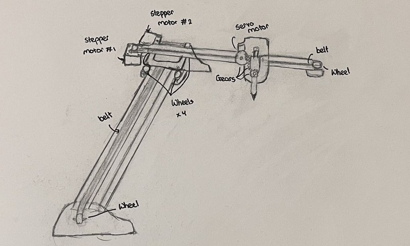
After a lot of brainstorming and discussion, we agreed on building a CNC pen plotter! 🤗
.png)
I feel like the entire process was a huge learning experience for us. This week really tested our teamwork and communication skills, as well as our ability to work under pressure. Personally, I’m very happy with what we were able to accomplish 🫡😄.
Individual Assignment
These were my individual contributions to the group assignment:
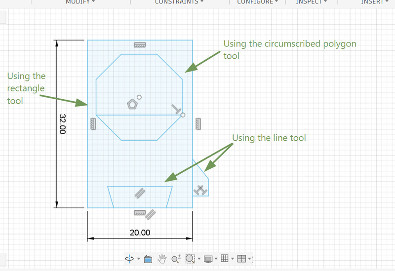
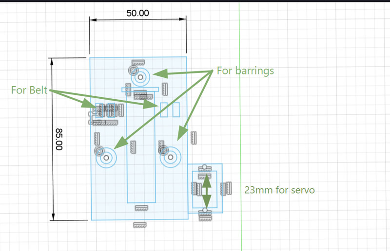
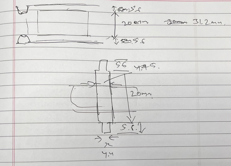
Since I was tasked with designing the frame of the pen plotter, I started by creating a sketch of the design:
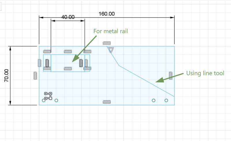
I used Fusion 360 for designing all the components. I first started with the frame:
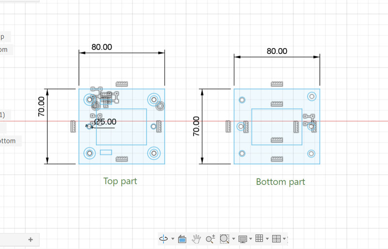
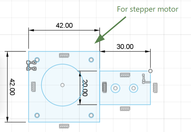
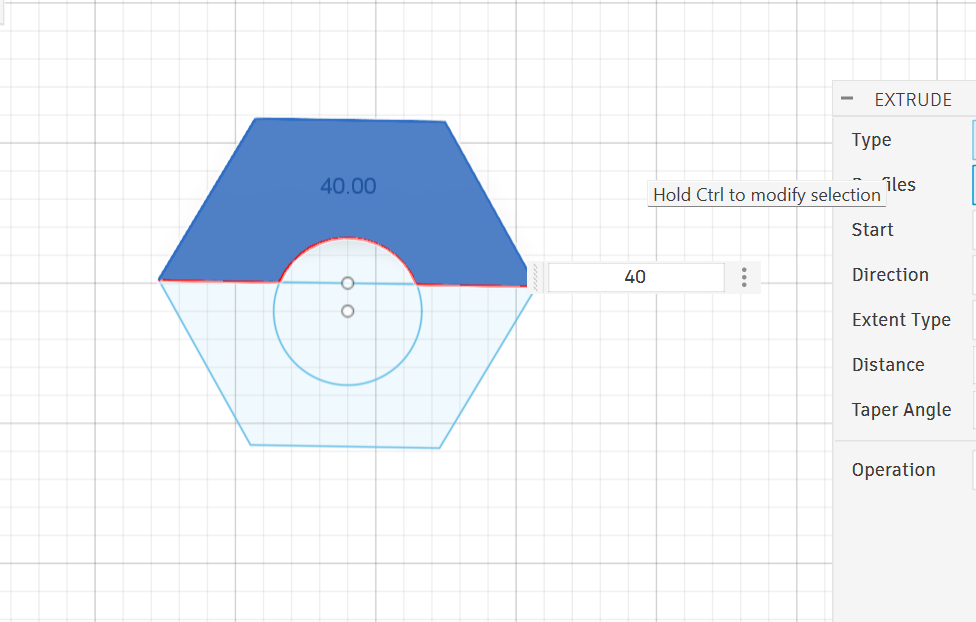
1. I created a sketch and used the following dimensions to create this structure.
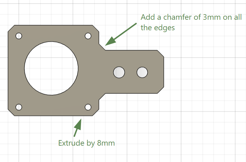
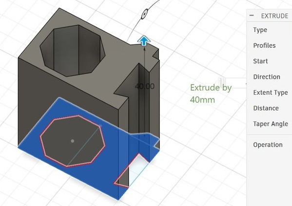
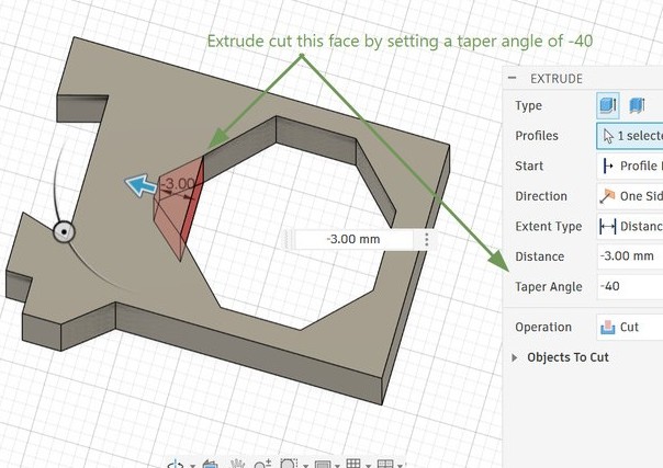
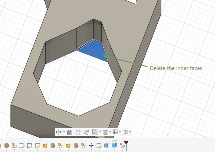
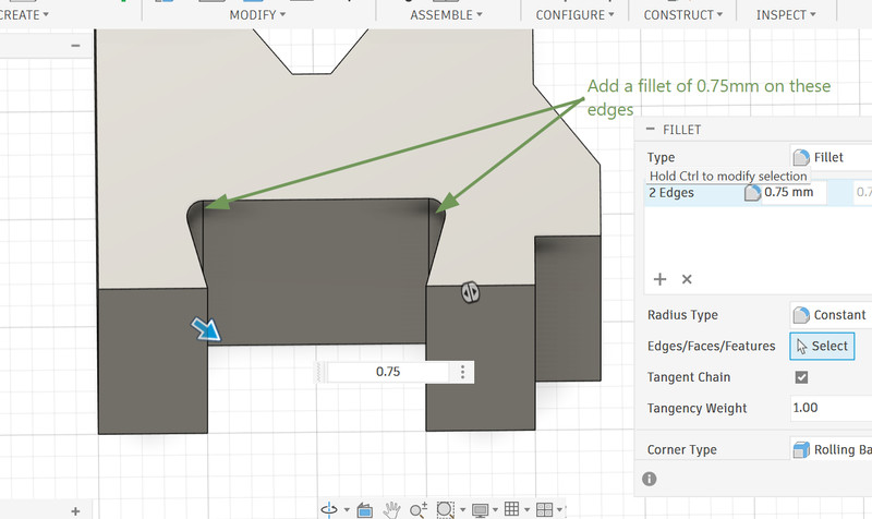
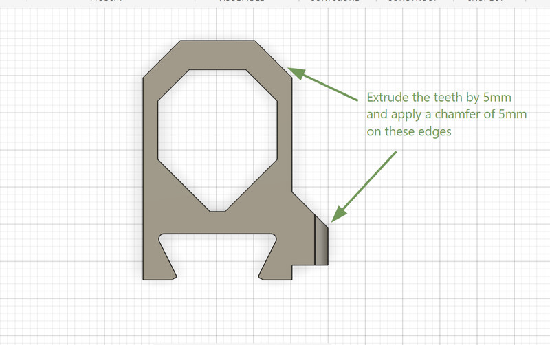
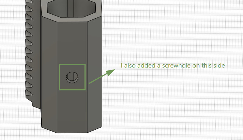
I then extruded some parts. I also used the fillet and chamfer tool on some edges.
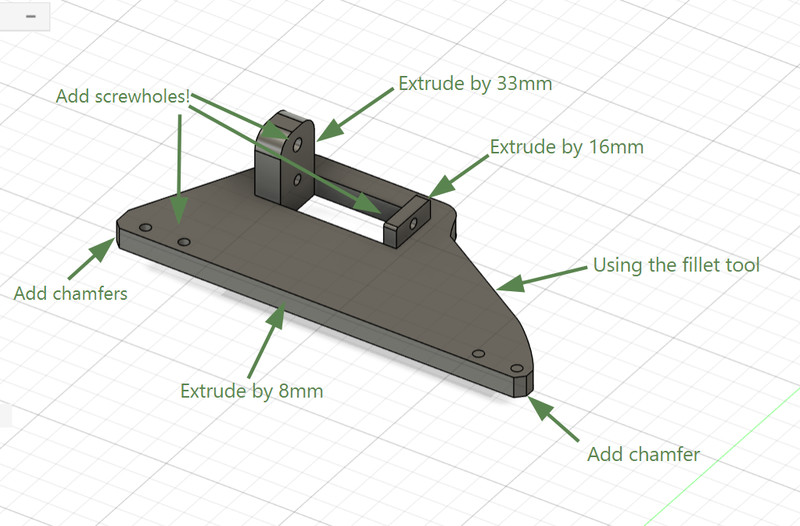
I mostly followed the same process for the other frame as well.
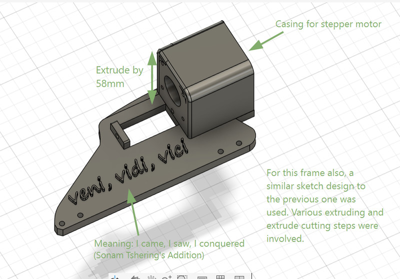
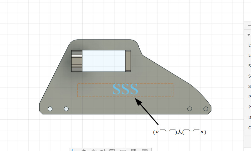
I didn't know that Fusion had a feature for adding text 😯. You can do so by first creating a sketch and then clicking on Create > Text. After that, all you have to do is extrude it (you can also extrude cut it if you want the text to be engraved)
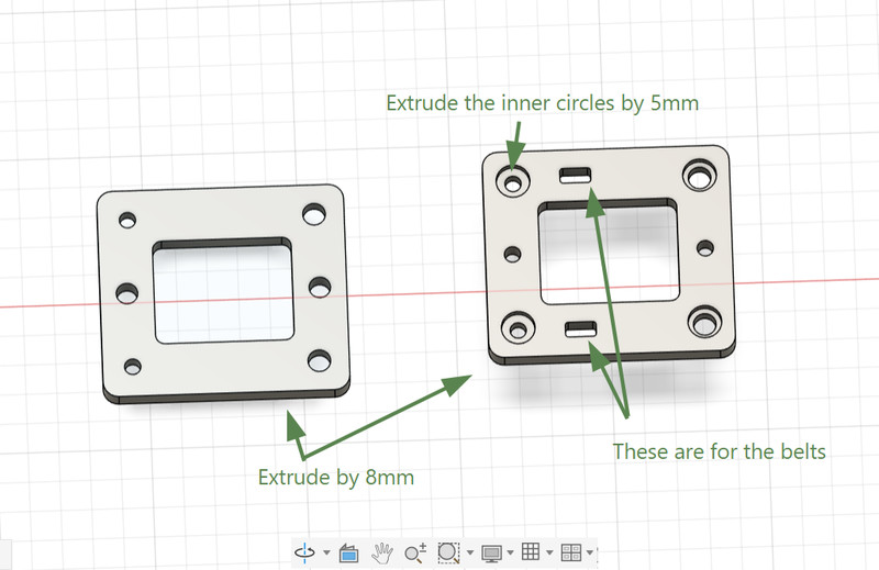
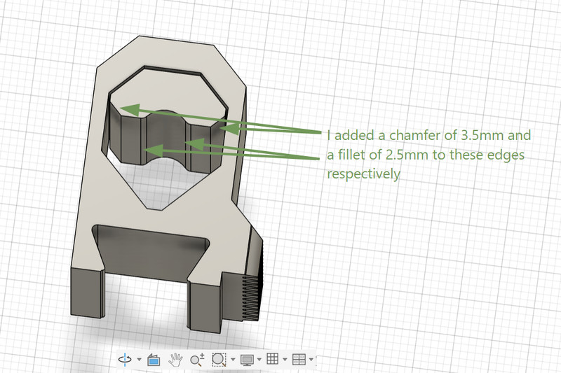
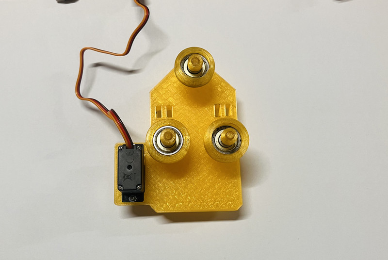
2. I then created the structure that connects the X and Y axis rods. It also allows the y axis rod to move.
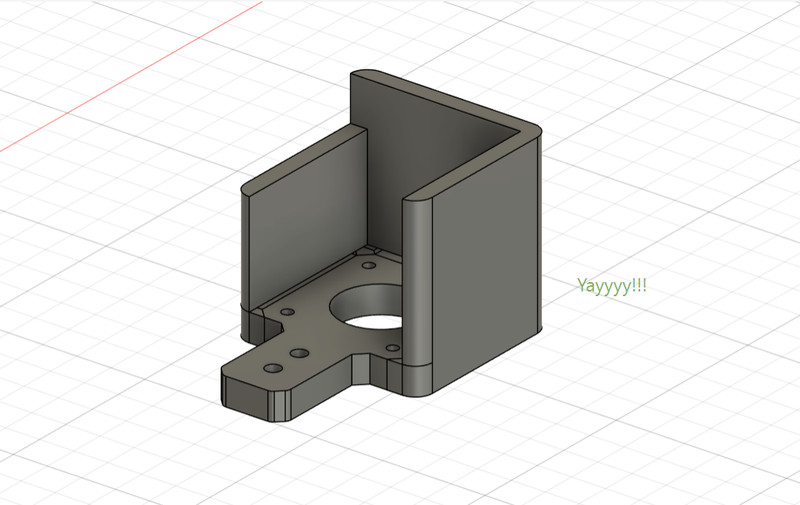
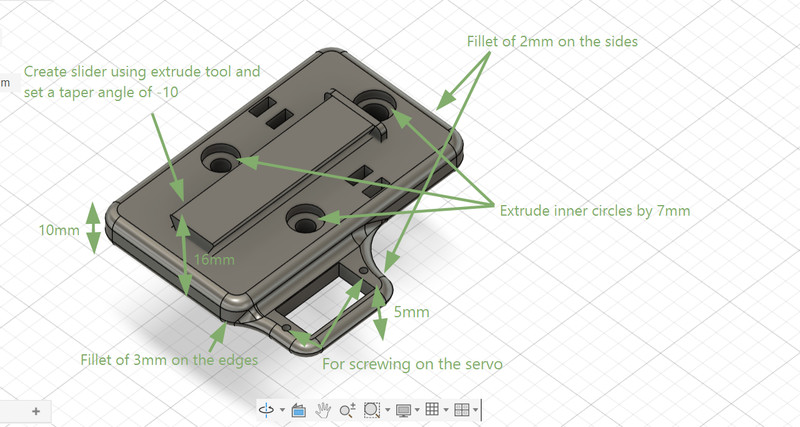
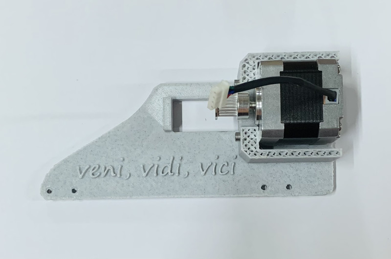
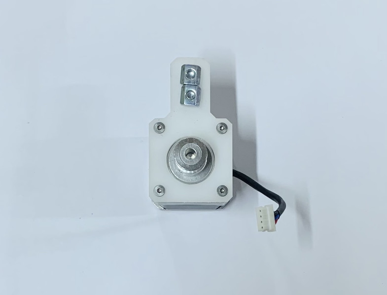
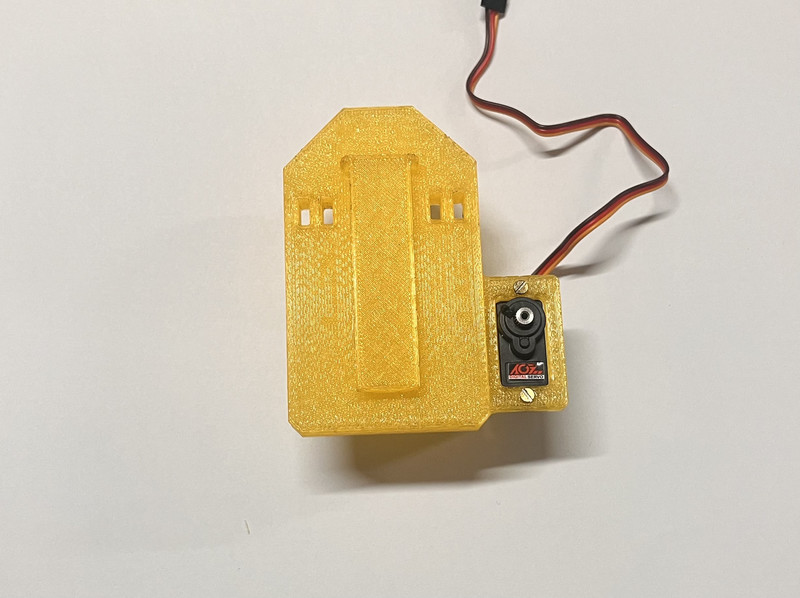
3. Next I proceeded to design the holder for the stepper motor.
After that, I extruded some parts and here is how it looks now! 😃
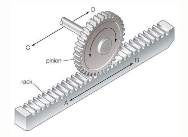
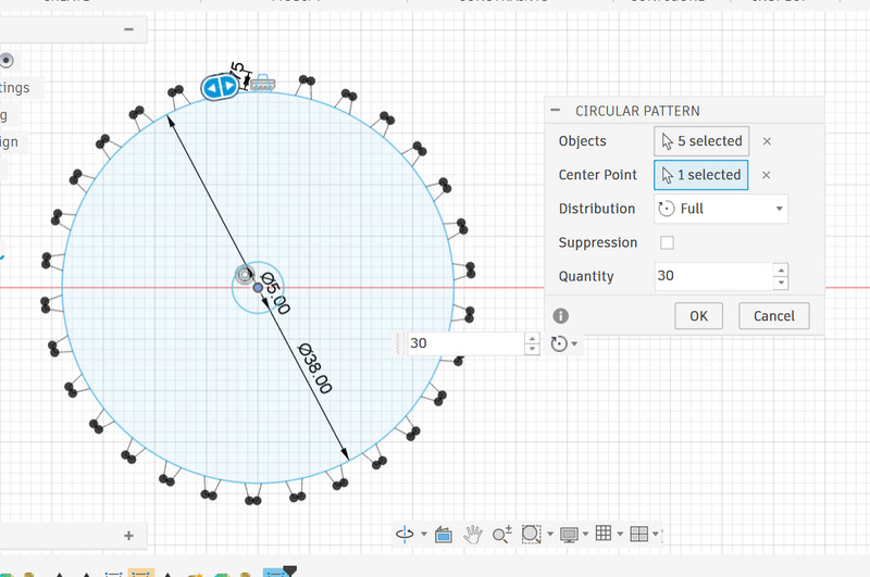
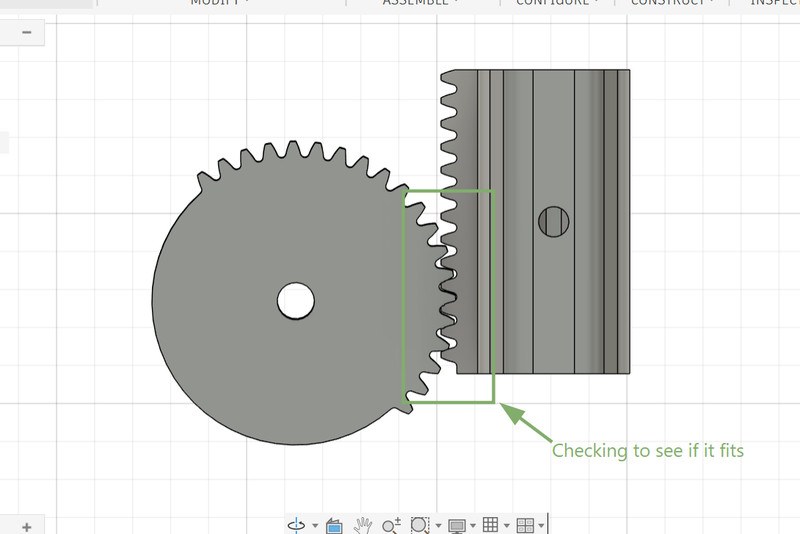
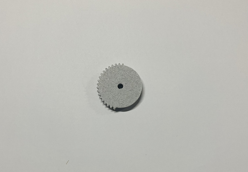
As for the pen holder part, we used a rack and pinion gear system.
A rack and pinion system is a simple mechanical mechanism used to convert rotational motion into linear motion. It consists of a circular gear called the pinion and a straight gear known as the rack. When the pinion rotates, its teeth engage with those on the rack, causing the rack to move in a straight line.
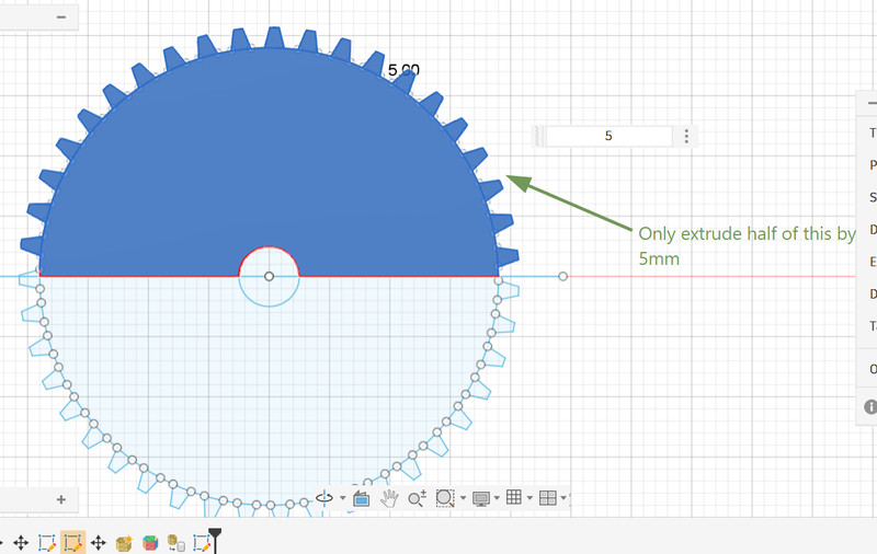
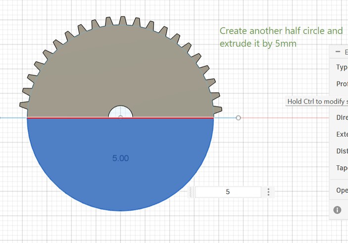
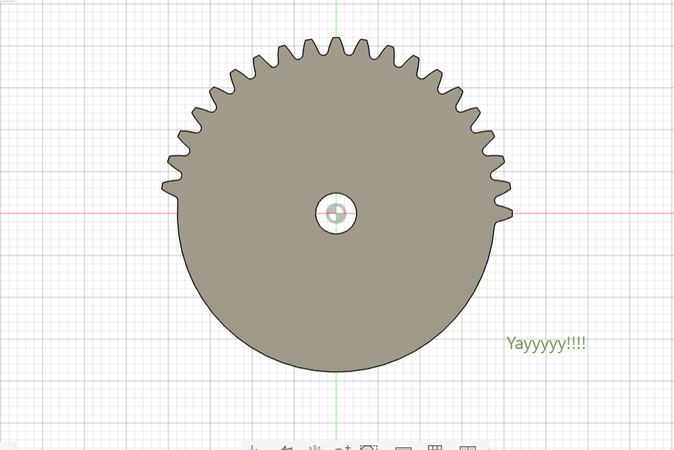
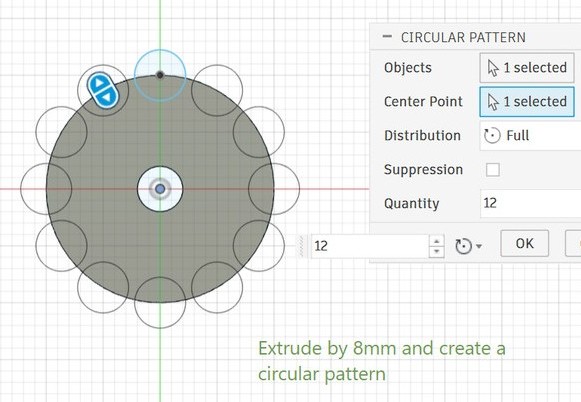
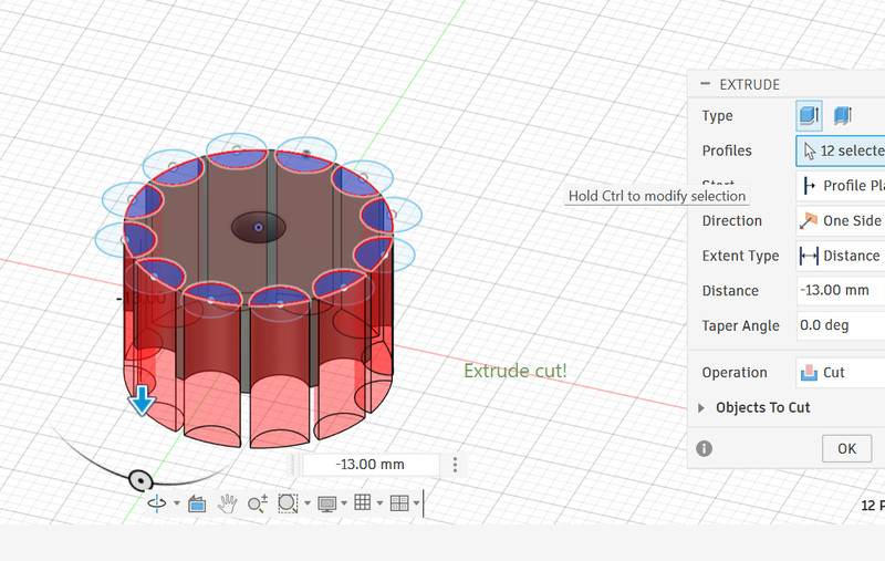
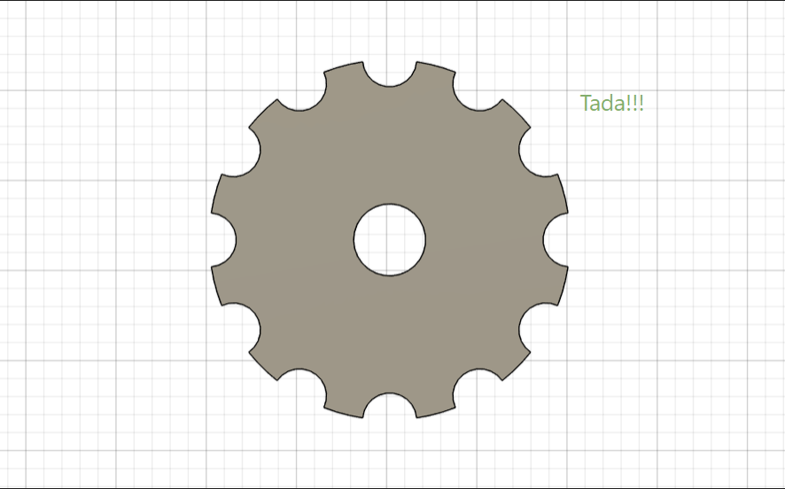
4. This is how I created the gear (pinion). To extrude only part of the circle, I used the line tool to split the circle into two halves.
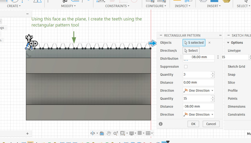
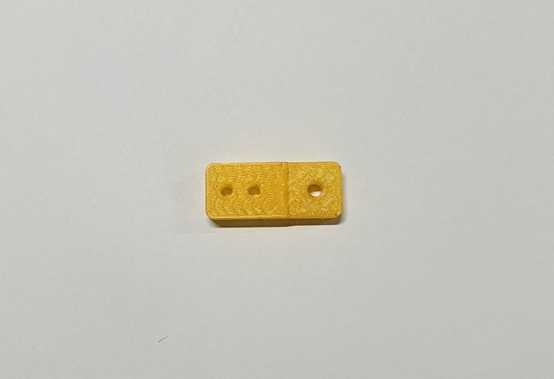
5. I then moved on to the rack.
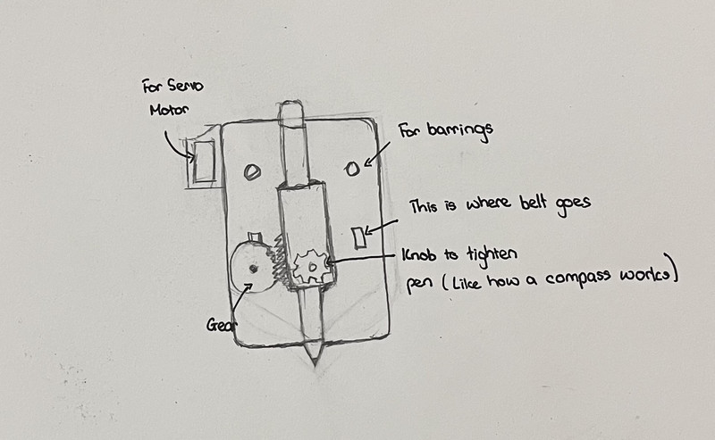
6. After finishing the design for the rack and the pinion, I started on the design for the penholder.
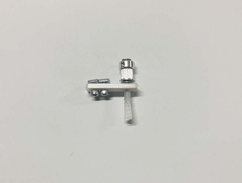
7. Similar to how a compass works, a knob was also designed for keeping the pen into place.

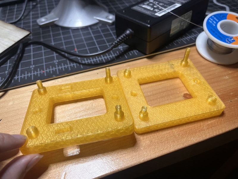
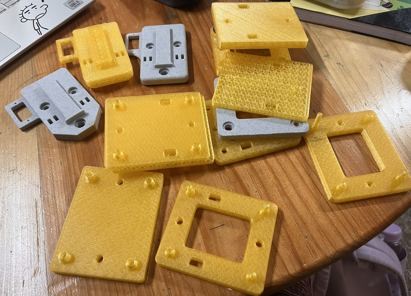
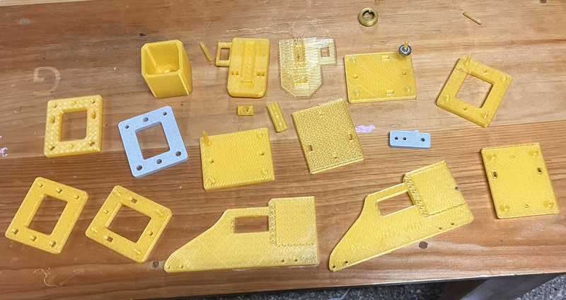
3D Printing
Here are the results! 🥳
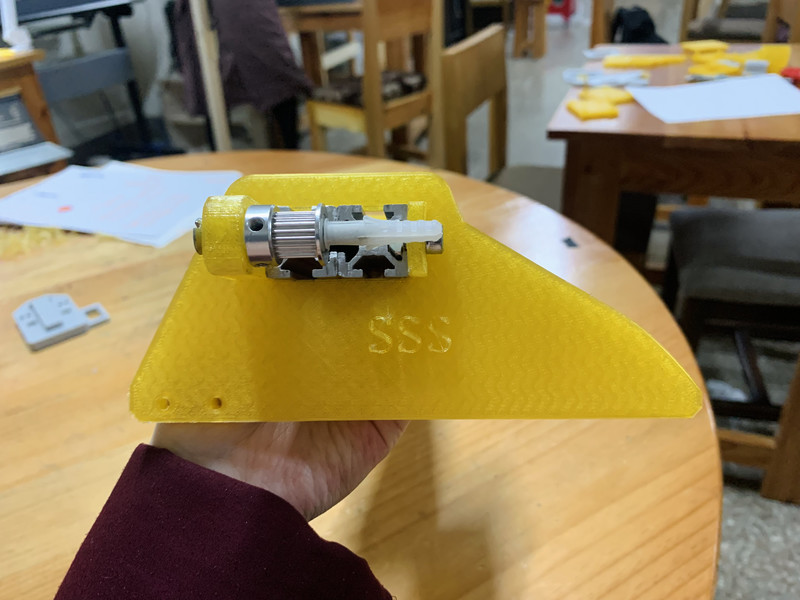
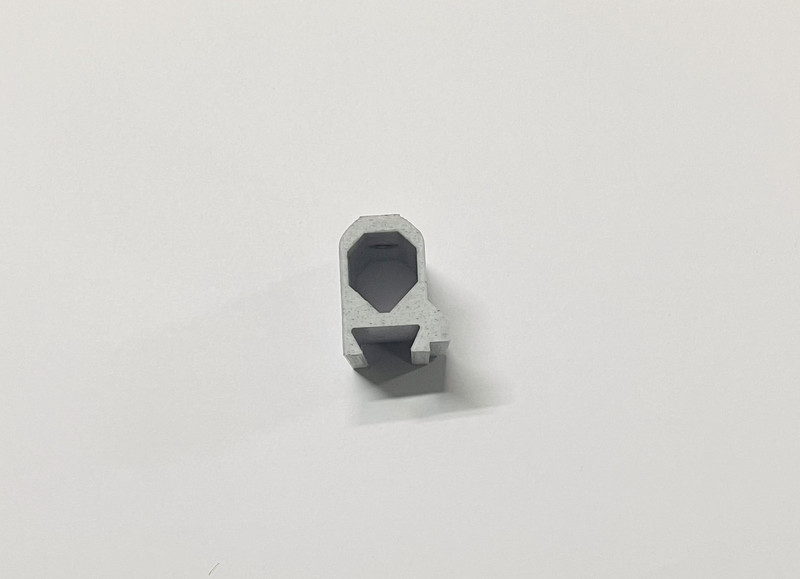
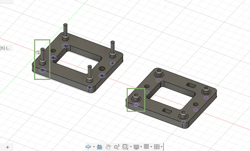
After printing the components, we noticed a few aspects that could be improved. Based on our local instructor Sir Anith’s suggestion, we decided to redesign the part so that it would no longer require screws.
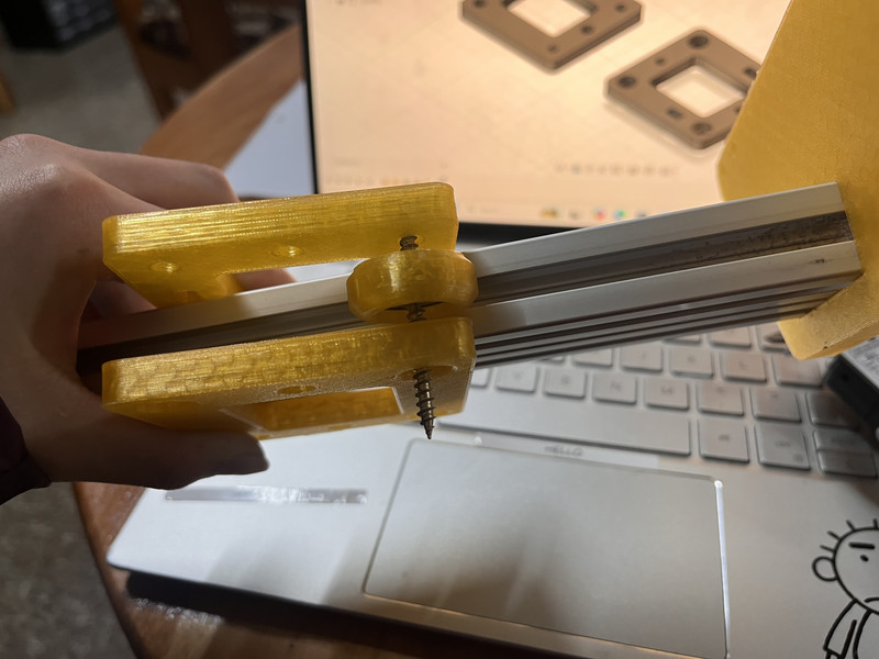
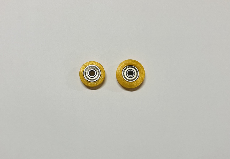
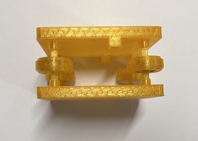
I modified the design in such a way that the pole fit the bearing precisely and was set at the right height to reduce friction during movement. However, the pole and the slot turned out to be quite fragile and were prone to breaking. 🫤
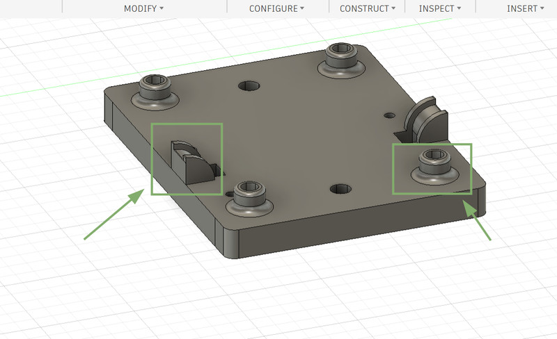
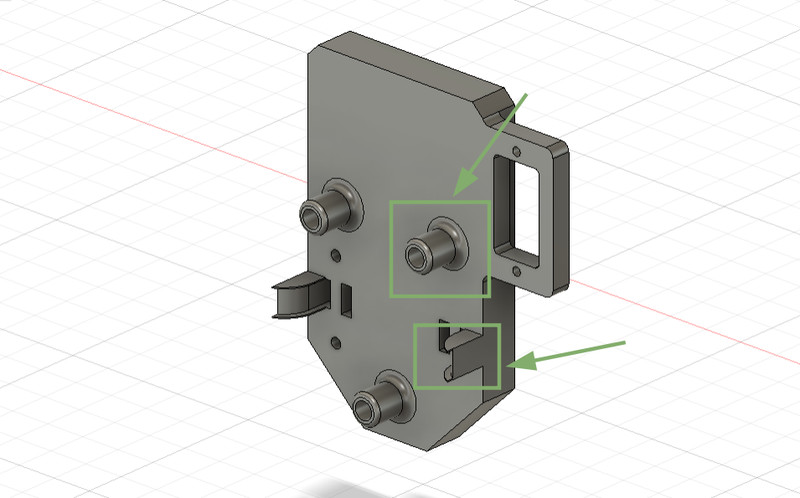
So instead of keeping the pole attached to the top intersection piece, I designed the pole as a separate piece and with Sir Anith's suggestion, added a fillet to the slots to reduce the chances of it breaking off. With sir's suggestion, I also added curved supports to keep the belt in position.
I did the same with the penholder as well.
I had to print these parts part several times to get the design and dimensions right.
After what felt like an eternity of modifying and testing, it finally worked!!! 🥳🤗😁
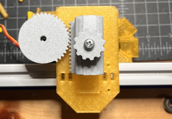
Testing
The rack and pinion worked!!! 🥳
The x and the y axis rods can move!!! 🥳
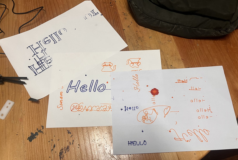
Here are some texts and drawings that we tried out with the plotter:
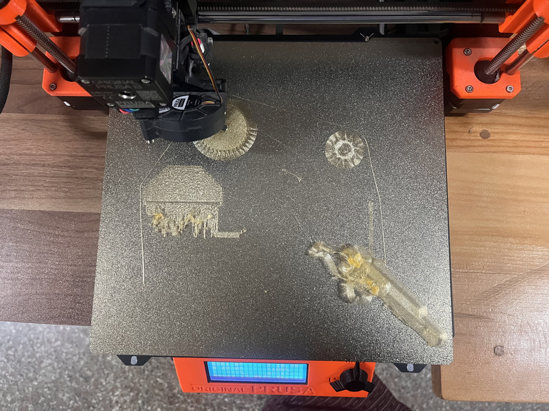
Over the course of two weeks, we did a lot of 3D printing 🤗, even though we were advised not to by our intructor. The printer gave us a lot of problems and we had a lot of failed prints. We even had to laser cut some pieces because the printer would not cooperate. 😅
.jpg)
You can access the design files by clicking on this link
I think it's safe to say that I'll probably never forget how to use a 3D printer again (like ever). It was a very stressful but equally rewarding week 🙂↕️. I'm giving this week a solid 9 out of 10.