Week 7 : Computer Controlled Machining
Group Assignment
- do your lab's safety training
- test runout, alignment, fixturing, speeds, feeds, materials, and toolpaths for your machine
Individual assignment:
- make (design+mill+assemble) something big (~meter-scale)
- extra credit: don't use fasteners or glue
- extra credit: include curved surfaces
- extra credit: use three-axis toolpaths
Learning Outcomes
- Demonstrate the development of a 2D design for CNC milling production.
- Explain the workflow involved in preparing a design for CNC milling.
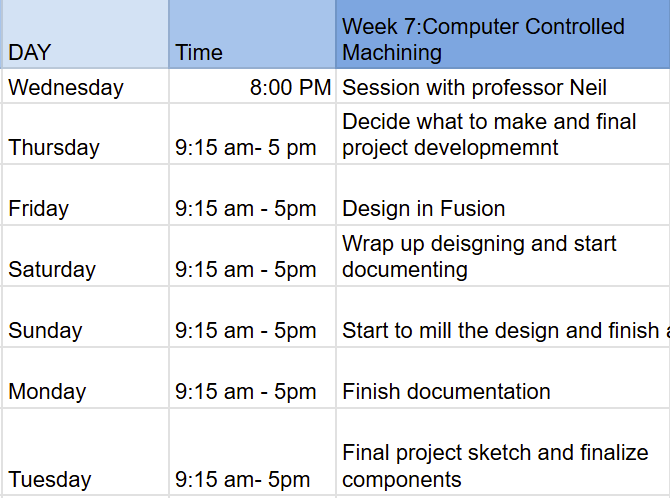
Here is my schedule for this week:
Group Assignment:
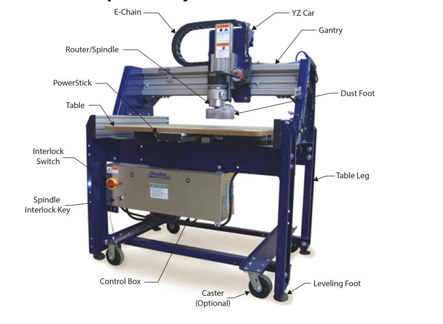
Below is a labelled illustration of the CNC machine used in our lab.
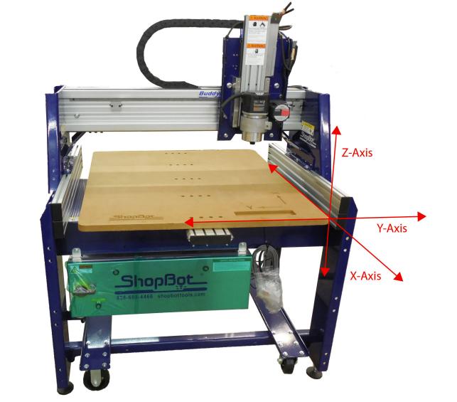
The following diagram shows the axis orientation of the machine, indicating the directions of the X, Y, and Z movements.
You can view the group assignment here.
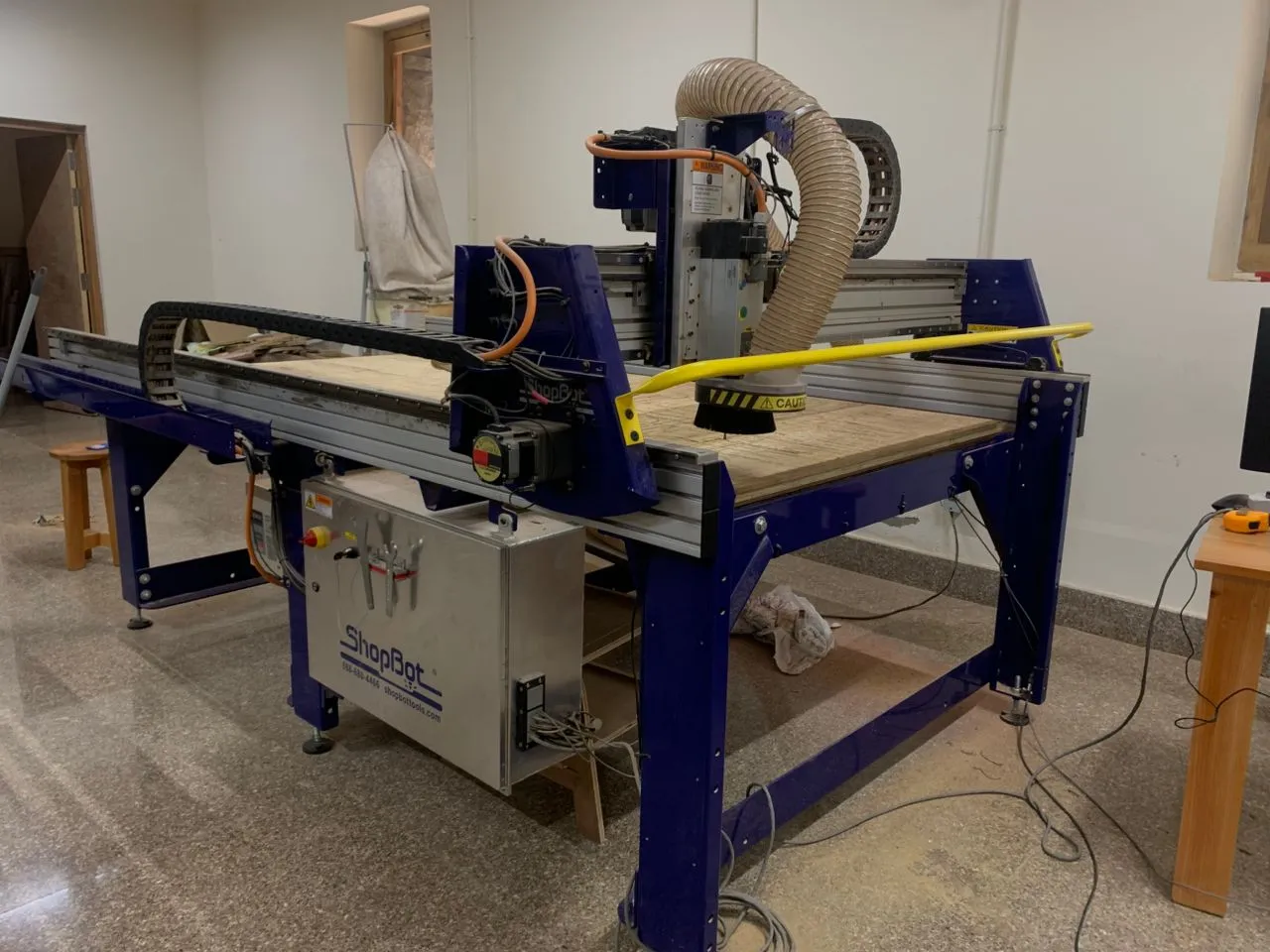
The CNC machine at our lab is the ShopBot PRS.
- Workspace: 2400mm x 1220mm
- Speed:We used the speed of 10,000 RPM to cut our design
- Software:ShopBot Control Software for operation
- Fixture: Cutting material is attached using clamps
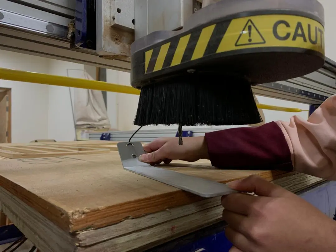
- Setting Origins:We use ShopBot3 software to set the X and Y origins. Proximity sensors are used to detect the edges of the material. For the Z axis, you have to manually set the origin through zeroing — you place a metal zeroing plate on the surface of the material, attach the clip to the end mill, and the machine slowly lowers the bit until it touches the plate to find the exact surface height.
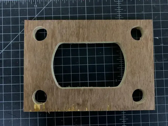
For this assignment, we created a simple design and followed a digital fabrication workflow to produce it using the CNC machine.
The object was designed in Fusion 360 and exported as a DXF file.

The design was then imported into VCarve Pro, where the toolpaths for cutting were created.The material was secured on the CNC bed, and the machine origins (X, Y, Z) were set before starting the job.For the cutting process, we chose a 15 mm thick plywood board.
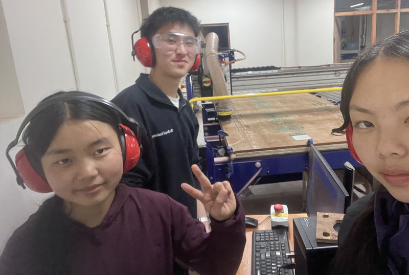
This was us before starting with the cutting procedure 😆
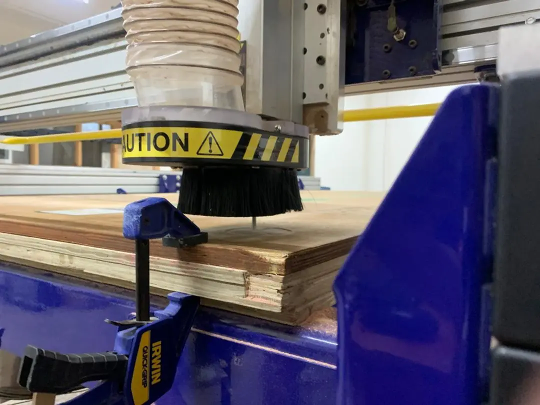
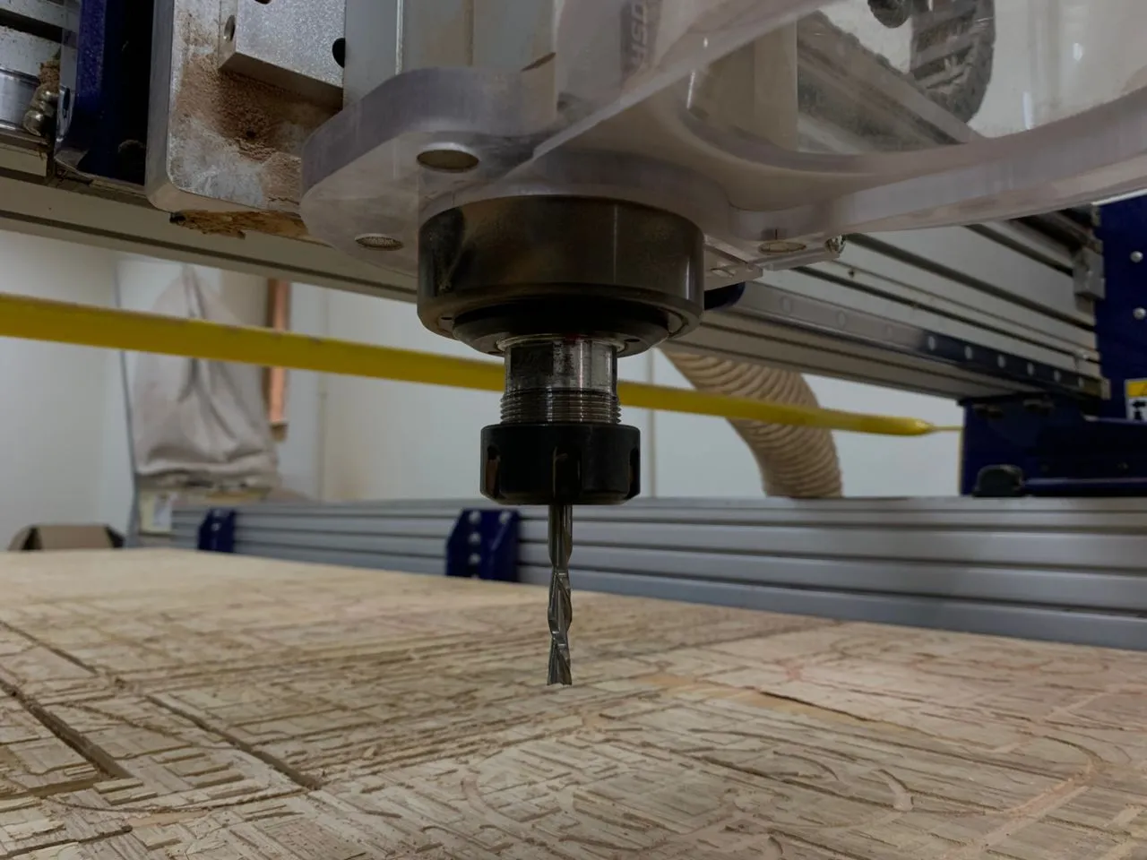
The wooden piece was secured on the ShopBot workspace using clamps. We used a 6 mm, 2 flute end mill for the operation.
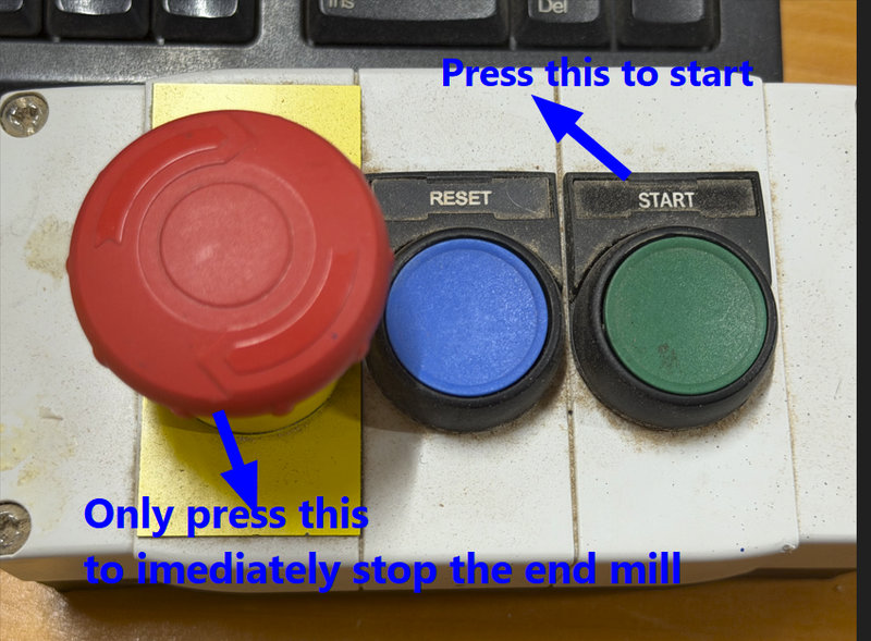
Emergency Stop Button
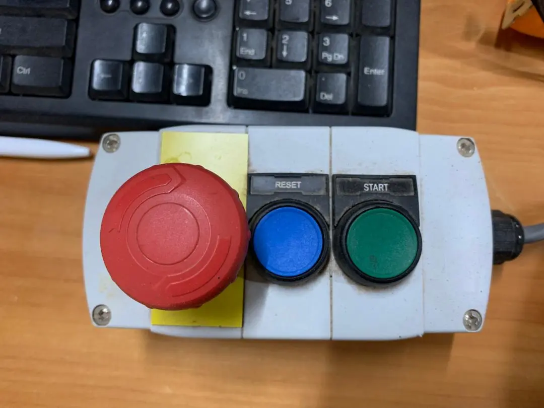
- Red button: This is the emergency stop button, which will immediately stop the machine when pressed.
- Blue button: This is the reset button, used right after turning on the machine.
- Green button: This is the start button, which makes the end mill begin rotating. Always press this before cutting — if the end mill isn't spinning when the machine starts moving, it will snap.
1. Runout
Runout describes the amount of side-to-side movement of the tool while it is rotating. If the runout is too large, the machine may produce inaccurate cuts, rough surfaces, and the cutting tool may wear out more quickly.
During our safety training, our instructor demonstrated how runout can be checked on the ShopBot machine. The procedure includes:
- Placing a dial indicator against the shank of the end mill (avoiding the cutting edges).
- Slowly turning the spindle by hand while watching the dial indicator to observe any variation in the reading.
For the ShopBot PRS machine, an acceptable runout value is generally below 0.05 mm. If the value is higher than this, it may indicate issues such as a worn collet, dirt inside the collet, or a damaged tool.
Before we began machining, our instructor verified that the runout of the machine was within the acceptable range. We also indirectly confirmed this during our test cut because the profile cuts maintained a consistent width along the entire path, with no noticeable irregularities.
2. Alignment
Proper alignment ensures that the spindle, cutting tool, and material are correctly positioned relative to one another before machining starts. This helps guarantee that the final cut matches the intended design.
To check the alignment of the machine, we followed several steps:
- X and Y Axis Alignment:Using the ShopBot3 software along with the machine's proximity sensors, we located the edges of the material and set accurate X and Y origin points. This ensures that the toolpath corresponds correctly to the actual position of the material on the machine bed.
- Z Axis Alignment:The Z origin was set using the touch plate zeroing method, which allows the machine to detect the exact height of the material surface and cut to the correct depth.
- Material Positioning:The plywood sheet was placed carefully against the corner of the CNC bed before clamping. This helped ensure that the edges of the material were aligned parallel to the machine's axes.
After the machining process was complete, we measured the dimensions of the test piece and found that they matched the original design measurements. This confirmed that the machine was properly aligned during the cutting process.
Safety Guidelines
When operating a CNC machine like the ShopBot PRS Standard, it is important to follow proper safety practices:
- Always wear safety glasses and hearing protection while the machine is running.
- Never leave the machine unattended during operation.
- Keep hands, hair, and clothing away from moving components.
- Use appropriate feed rates and spindle speeds based on the material.
- Make sure the workpiece is securely clamped or fixed before starting the job.
- Regularly inspect the machine for loose parts or wear.
- Avoid wearing loose clothing, and tie back long hair to prevent accidents.
- Keep the emergency stop button within reach in case the machine needs to be stopped quickly.
- After machining, remove any dust or debris from the workspace to keep the machine clean and safe.
Individual Assignment:
CNC Machine
A CNC (Computer Numerical Control) machine is a manufacturing tool operated by computer software rather than manual control. It translates design files (CAD) into precise, automated movements using code to direct drills, or cutters to shape materials like metal, wood, or plastic with high speed and accuracy.
For this week’s assignment, which involves designing, milling, and assembling something large, I decided to create a simple piece of furniture that is also useful. After choosing between a table and a mini bookshelf, I decided to make a table since the assignment requires the furniture to be at a meter scale size.
To deisgn the table, I used the software Fusion 360 since I was more familiar with that software.
I started my design by defining parameters for dimensions that I would use a lot, like the thickness of the material. Since the exact thickness wasn’t confirmed at the beginning of the week, I temporarily set it to 18 mm. This way, I could easily adjust the parameter later if the material thickness needed to be changed.
To add and modify parameters, navigate to 'Modify' and from the dropdown, choose 'Change Parameters'
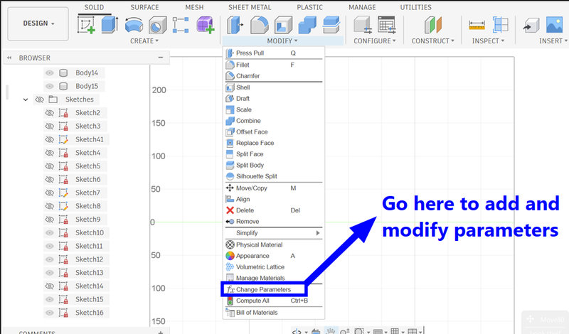
Then, click on the plus sign to add new parameters and enter the required values, such as the measurement and the name of the parameter, which can also be written as text.
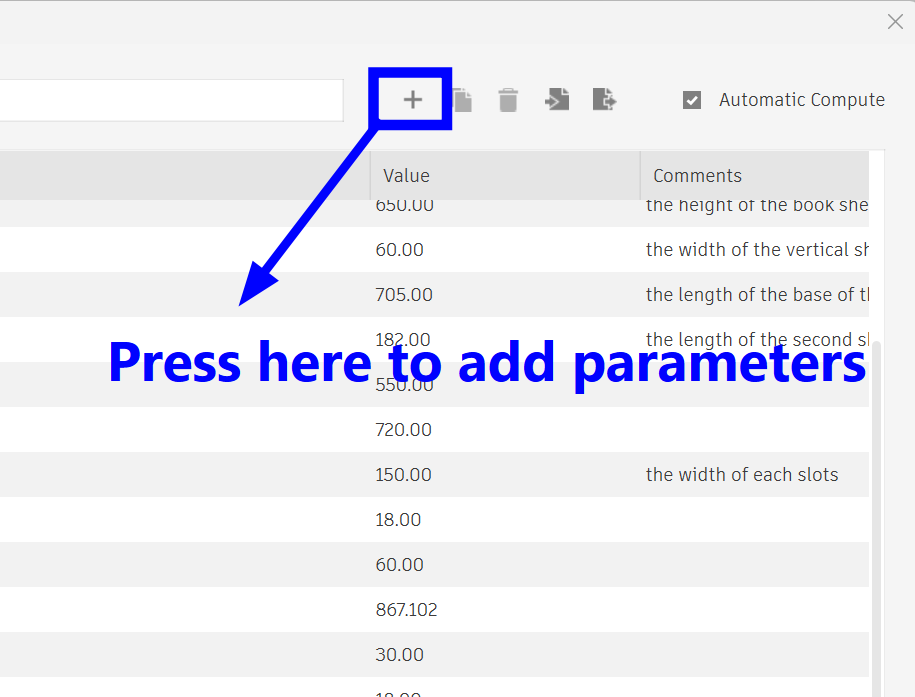
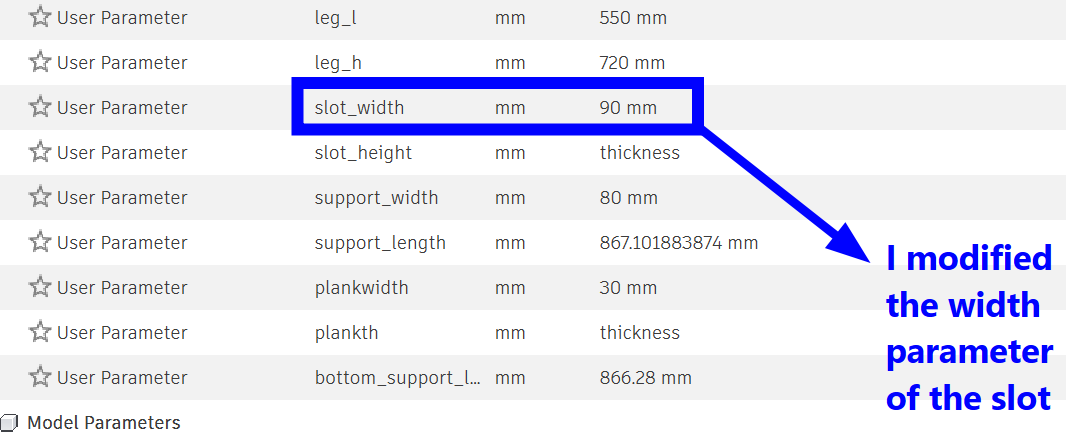
These were all the parameters I've used for my design:
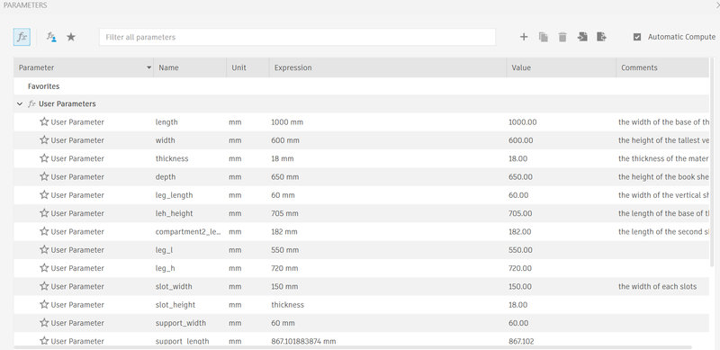
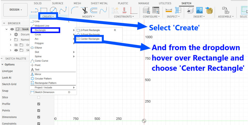
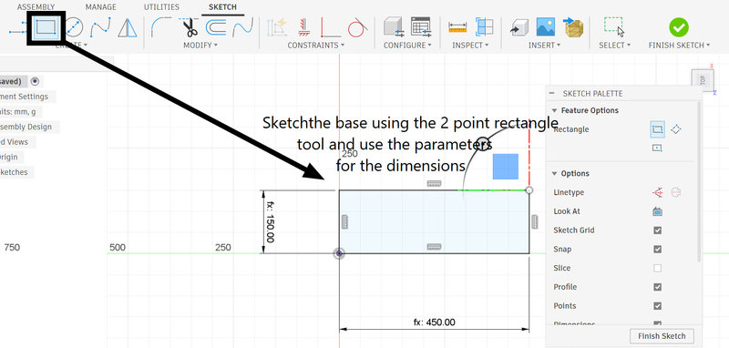
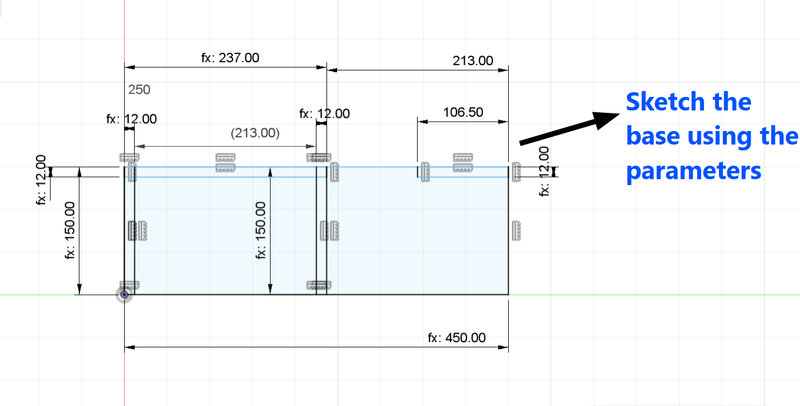
Next, I began by creating a sketch of the base of the table. I used the Center Rectangle tool to draw the rectangles and set the dimensions using the pre-defined parameters for the height and length.
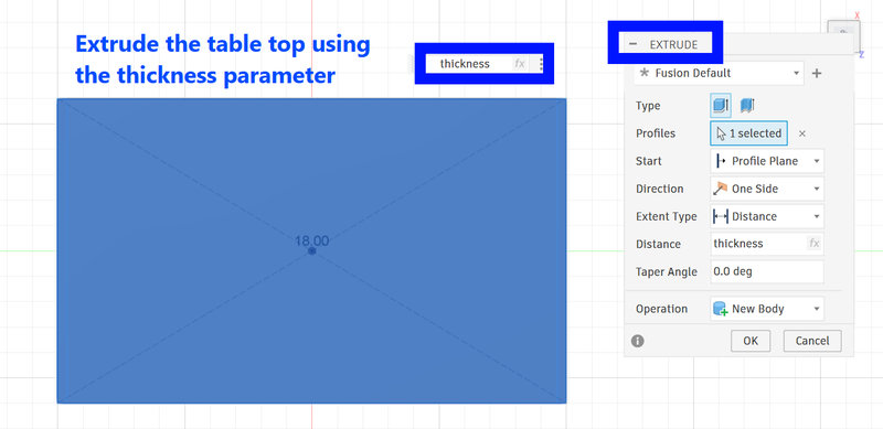
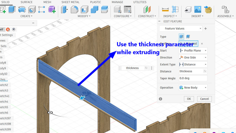
Then I extruded the sketch of the tabletop and used the thickness parameter to set the depth of the tabletop.
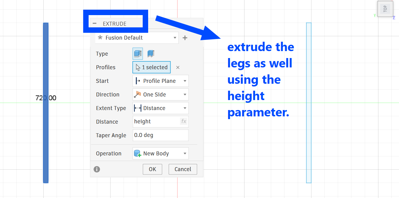
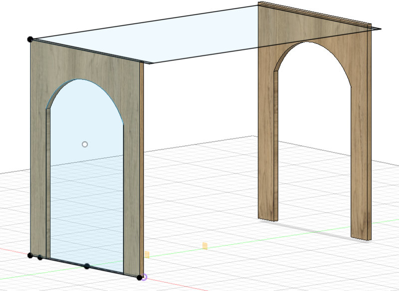
Then, I created the table legs by sketching them in a similar way as the tabletop. I set the width of each leg to match the breadth of the tabletop, which was 60 cm, and used the height parameter of 72 cm for the legs.
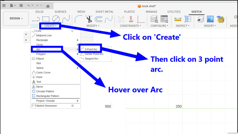
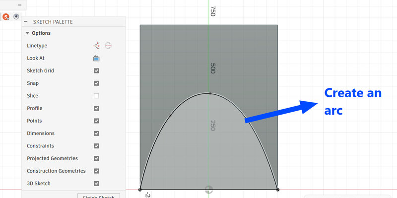
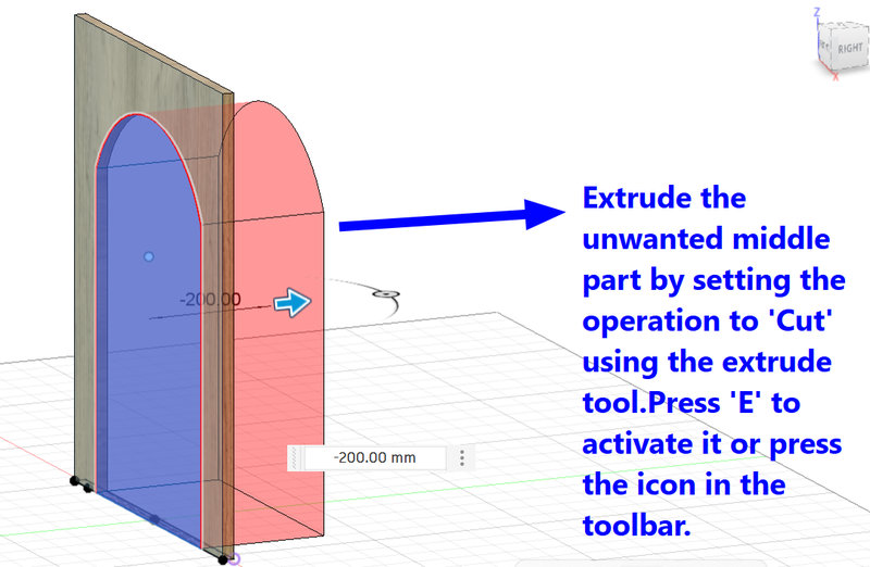
After that, I used the Arc tool to sketch a curve on the leg and removed that section while extruding to shape the leg.
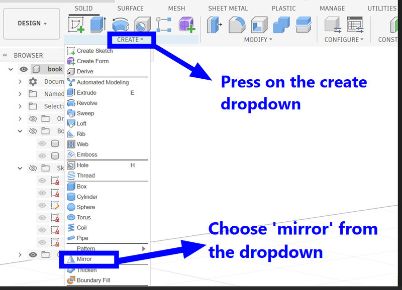
Then mirror the leg using the mirror tool
Next, I created slots for each leg. I added two slots on every leg, each measuring 150 mm by the material thickness..
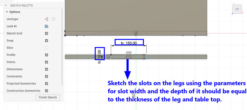
Opps 🤦♀️ turns out 150mm for the slot width was a bit too, long. So I changed the slot width parameter to 90mm instead.
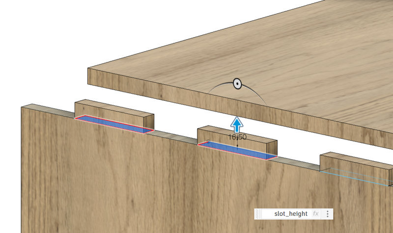
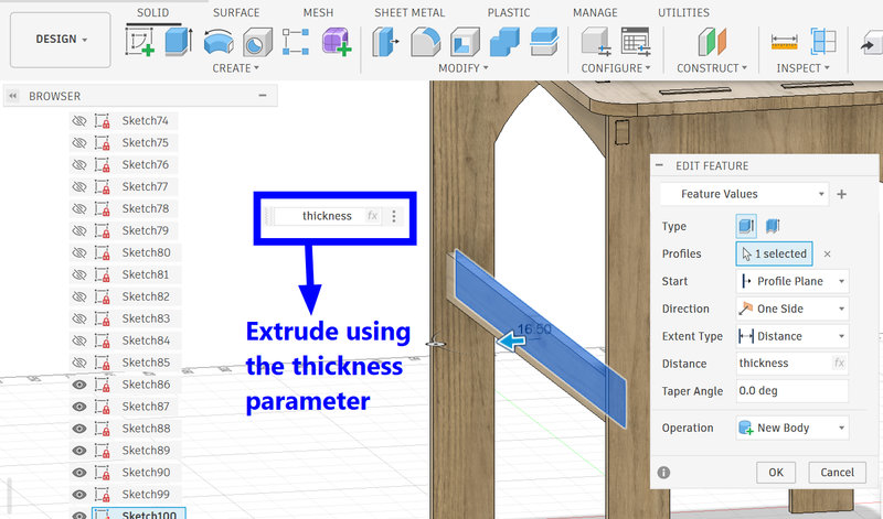
Then extrude the slots, and set the height of the slot to the thickness of the material using the thickness parameter:
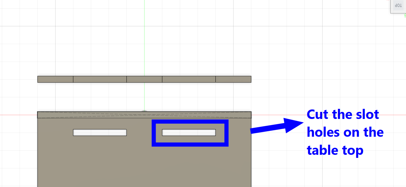
After that, I sketched the slots on the tabletop, positioning them carefully so that when I cut out the sketch, the legs would slide into the slots properly.
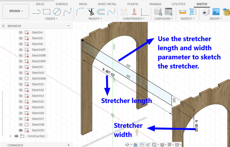
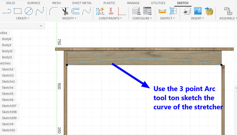
I repeated the same process for the other leg and then sketched the table stretcher using parameters to provide extra support.I wanted the stretcher to have a curved feature, so I used the 3 point arc tool to draw a curve on the stretcher and extruded the arc out.
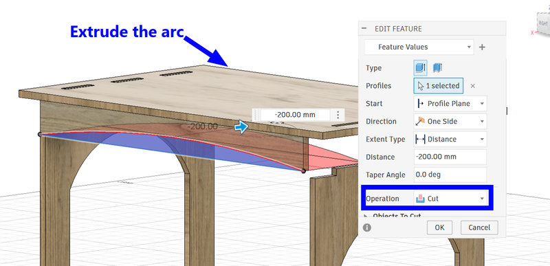
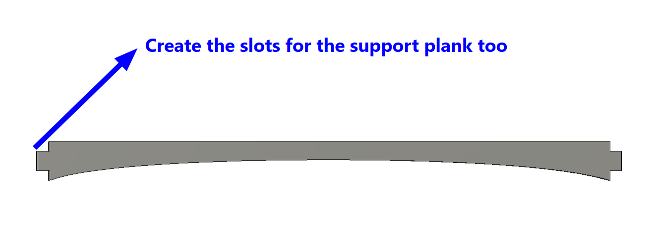
I mirrored the arc to the other side and then created slots for the stretcher as well with two slots for the tabletop and one slot on each end of the stretcher to connect to the legs.
I used the Fillet tool to round off the corners of the tabletop, to make them look smooth and more finished:

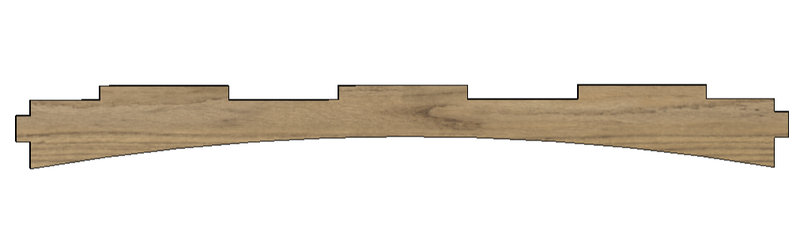
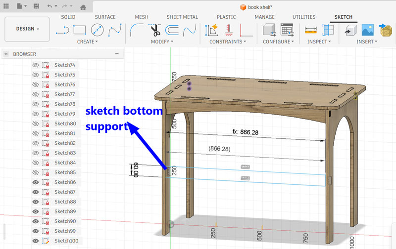
Next, I added the bottom supports connecting the two legs. Similar to the stretcher, I sketched the bottom support using the 2 point Rectangle tool, with the length extending from one edge of the leg to the other and a width of 60 mm.
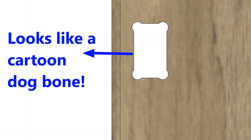
Dogbones:
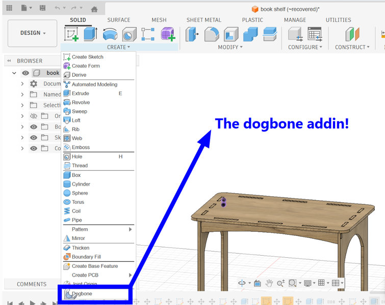
Next, I added dogbone fillets to the design to ensure the parts could be cut accurately with the CNC machine. Dogbones are small circular cutouts added to the inside corners of slots. Since CNC milling bits are round, they cannot create perfectly sharp internal corners. By adding dogbones, extra space is created in the corners, allowing the rectangular parts to fit together properly after milling. This helps ensure that the joints slide together smoothly during assembly.I followed azhim Tsheltrim's week 7 assignment page to add dogbones:
Download dogbone addin for fusion from here
Steps for Adding the Dogbone Addin in Fusion:
- Start by downloading the Dogbone addin from the link and extracting the downloaded file.
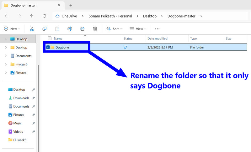
- After extraction, rename the folder Dogbone_master to simply Dogbone, then copy this folder.
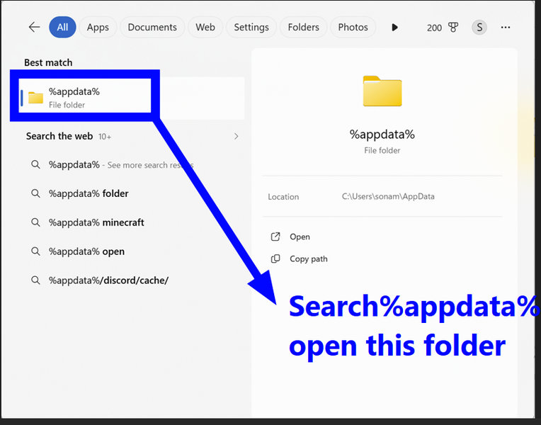
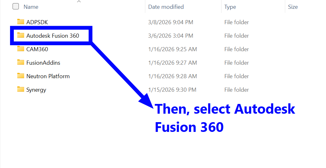
- Open the Run window by pressing Win + R, type %appdata%, and press Enter.
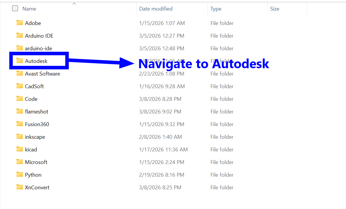
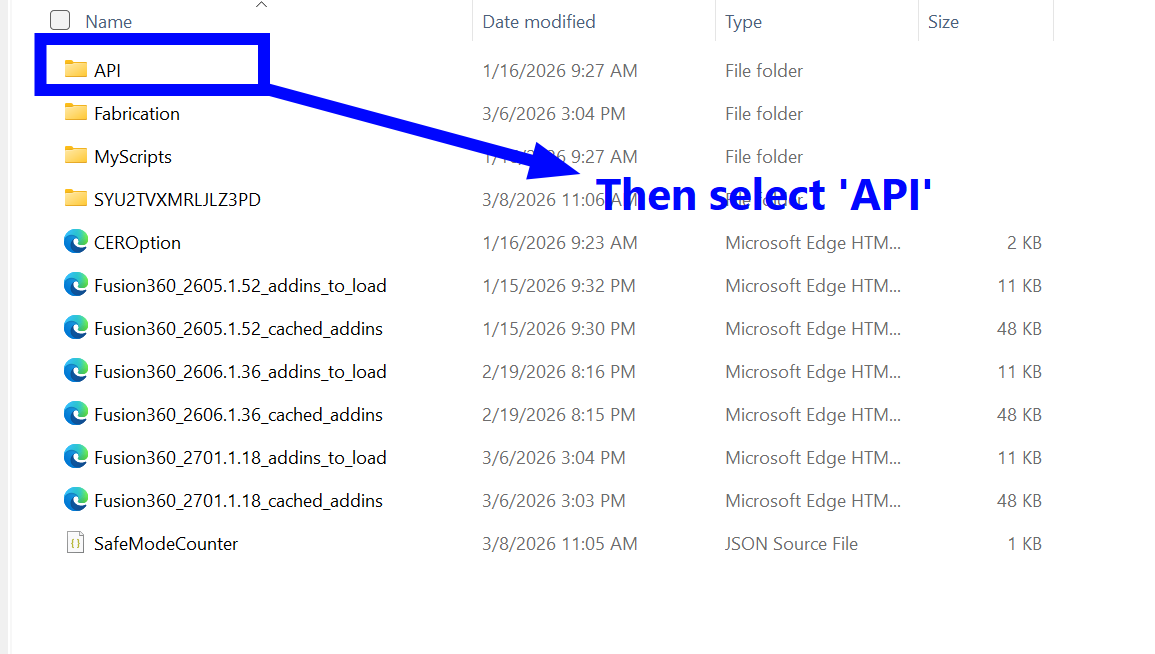
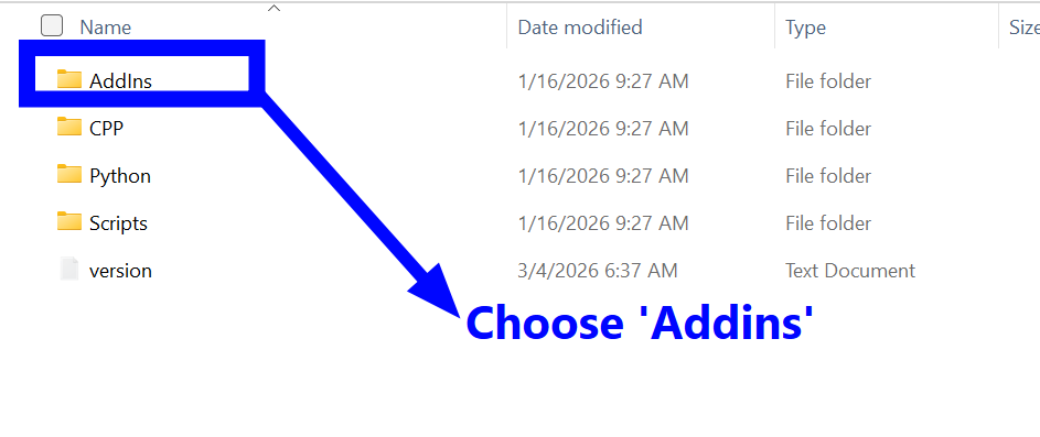
- In the folder that opens, go to Roaming → Autodesk → Autodesk Fusion 360 → API → AddIns.
- Paste the copied Dogbone folder inside the AddIns folder.
- Launch Fusion 360.
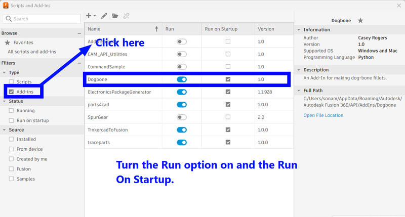
- Navigate to Utilities, then open AddIns tab.
- Look for Dogbone in the list of available addins.
- Turn on Run on Startup so the add-in loads automatically whenever Fusion starts.
- Finally, press Run to enable the Dogbone add-in.
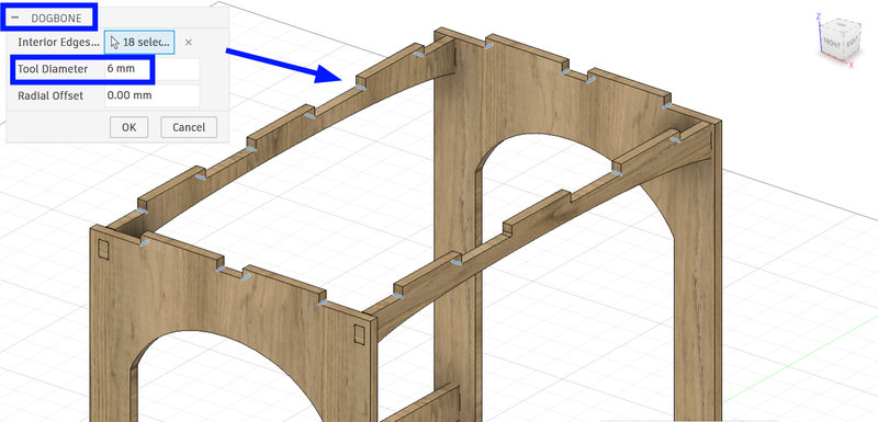
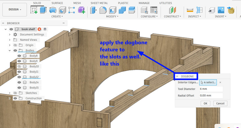
Use the dogbone addin for your deisgn for slot holes and the sides of the finger slots:
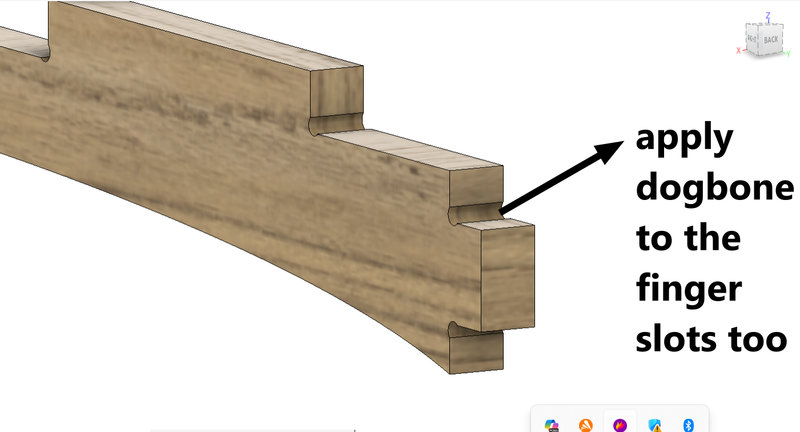
And it sort of does look like a cartoon dogbone 😃
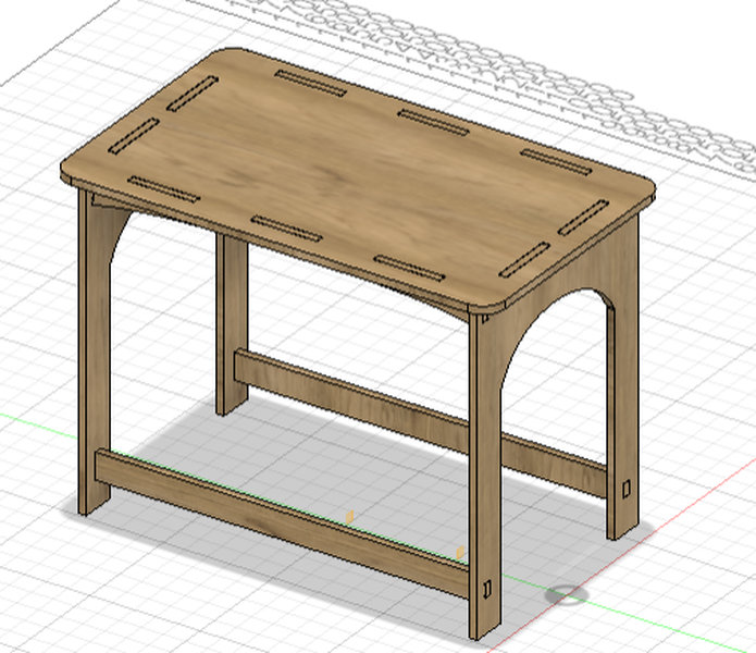
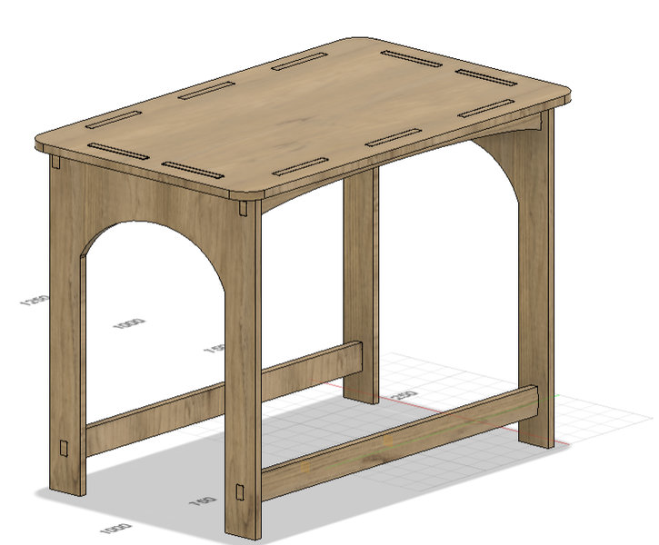
This is the final result of my table design:
I uploaded the deisgn to sketchfab as well:
Before we begin milling the design, we need to export the 3D model as a DXF file. Similar to how laser cutters use DXF files or 3D printers use G-code, a DXF file acts like a language that the CNC machine can understand. This step translates our digital design into instructions that the machine can follow to accurately cut and shape the material.
- Arrange all the components of your design by placing them one by one.
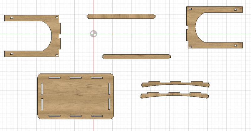
- Click on Create Sketch and select the horizontal plane. Press P to use the Project tool. Then click on each component to project its outline onto the sketch. You should see a purple sketch appear on each component, showing the projected geometry.Since the CNC machine follows 2D vector paths, we only need the sketches for exporting. Projecting the components allows us to capture their outlines accurately.
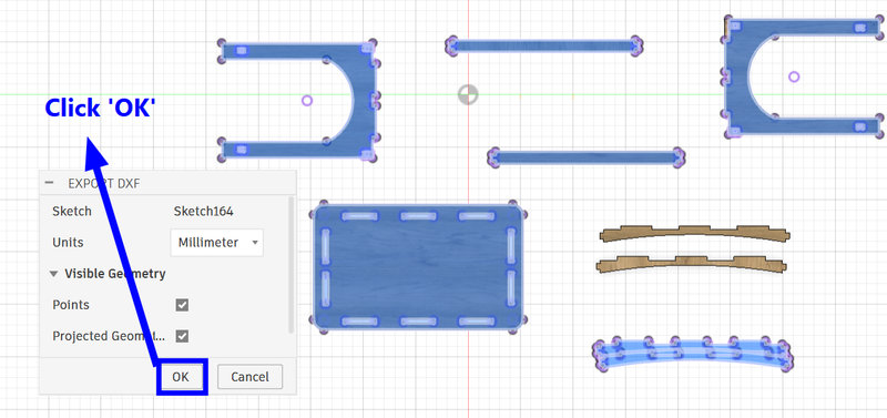
- Once all the sketches are projected, a new sketch will appear in the browser panel containing all the projected outlines. Select this sketch, click Export, and choose the DXF file format.
Milling Process:
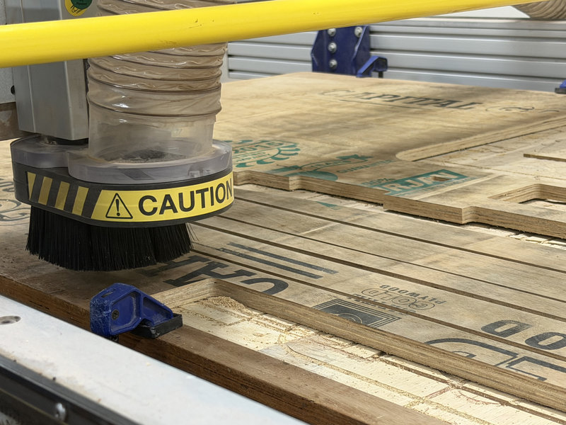
Loading and Securing the Material
First, I placed the wood on the CNC bed. To keep it from moving during cutting, I set the clamps carefully. Properly clamping the board is really important for both safety and accuracy, ensuring the material stays stable for precise milling.
Generating a Toolpath in VCarve Pro
CNC toolpaths are the specific, programmed routes a cutting tool follows to remove material and create a part, acting as a "roadmap" for the machine. They are created in CAM software and control the tool's movement, speed, and depth — all converted into G-code that the CNC machine understands.
Vcarve
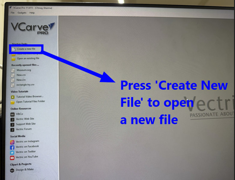
I used VCarve Pro 11.0 to generate the toolpaths for my design. VCarve Pro is a powerful, user friendly CAD/CAM software suite developed by Vectri. The software is a complete software solution for CNC routing, sign making and engraving. This is the software many professional sign shops and fabricators use. While the software can import your designs from other programs, it also contains a complete all the tools needed to create your designs right in the program.
Open the software and select 'New File'.

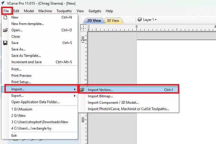
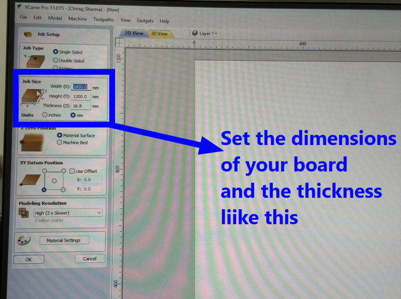
I updated the page dimensions in the software to match the real size of my board and entered the material thickness.Then import your design file by naviagting to 'Import' and select 'Import Vector files'
Next, I selected the imported design and organized the components to minimize material waste.Make sure nothing overlaps and that spacing is sufficient for the cutting tool.
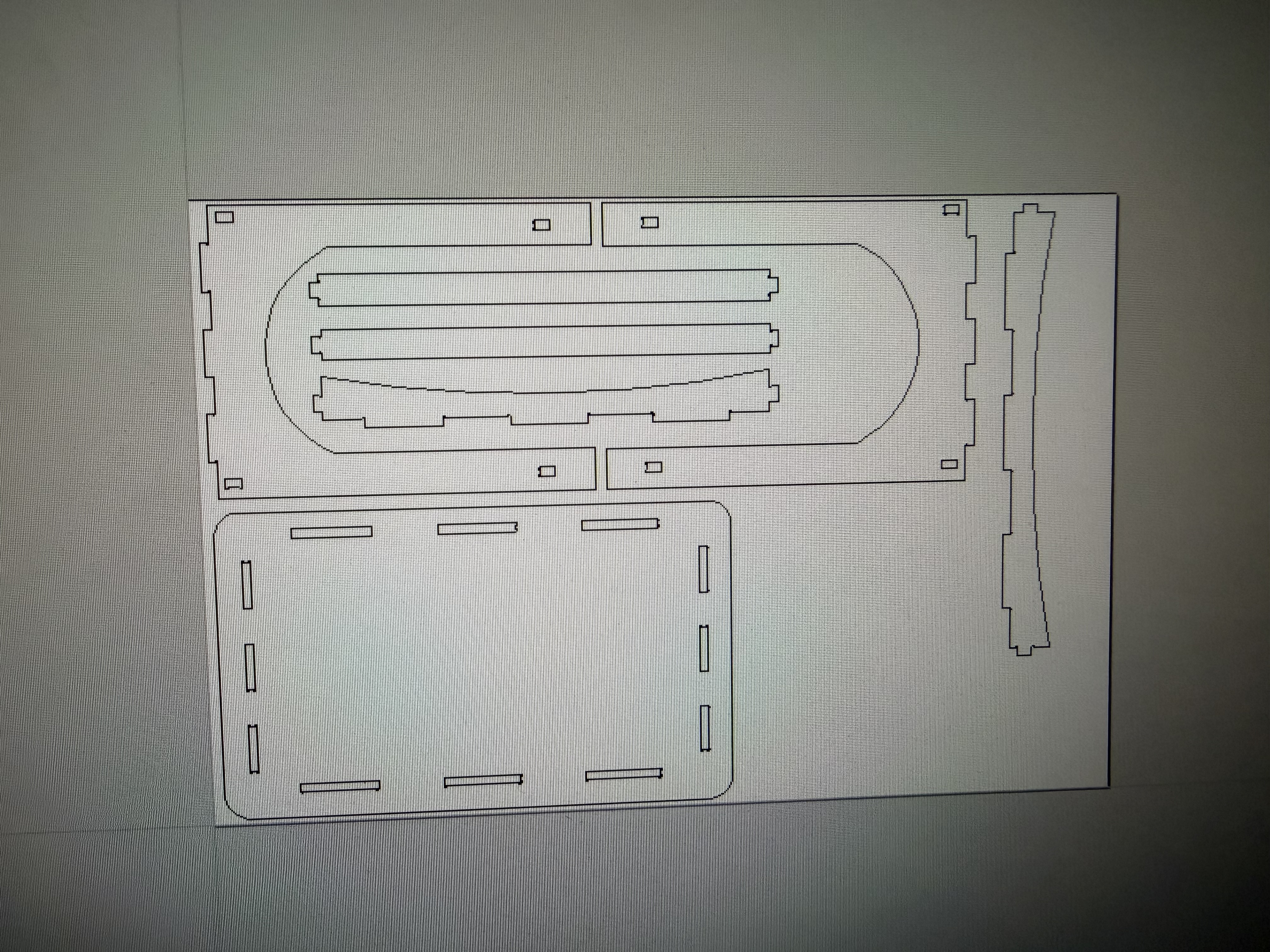
-
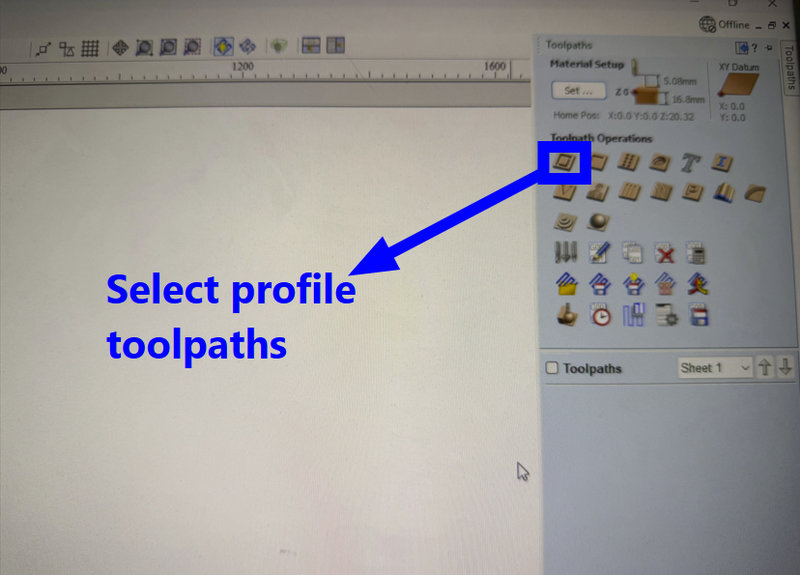
Select the Toolpath Type
- Click on the Toolpaths tab.
- Choose the type of toolpath depending on your operation:
- Profile Toolpath: For cutting along the outline of a part.
- Pocket Toolpath:For clearing out areas inside a shape.
- V-Carve Toolpath:For engraving or detailed designs.
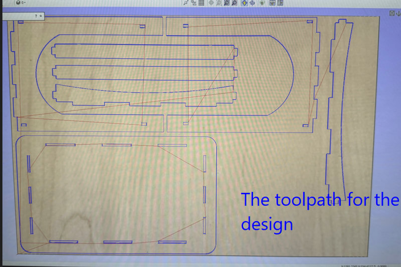
This was the toolpath for my design:
-
Choose Your Tool
- Select the appropriate cutting tool (end mill, ball nose, V-bit) based on your design.
- Input the tool dimensions like diameter, tip angle, etc to cut accurately.
-
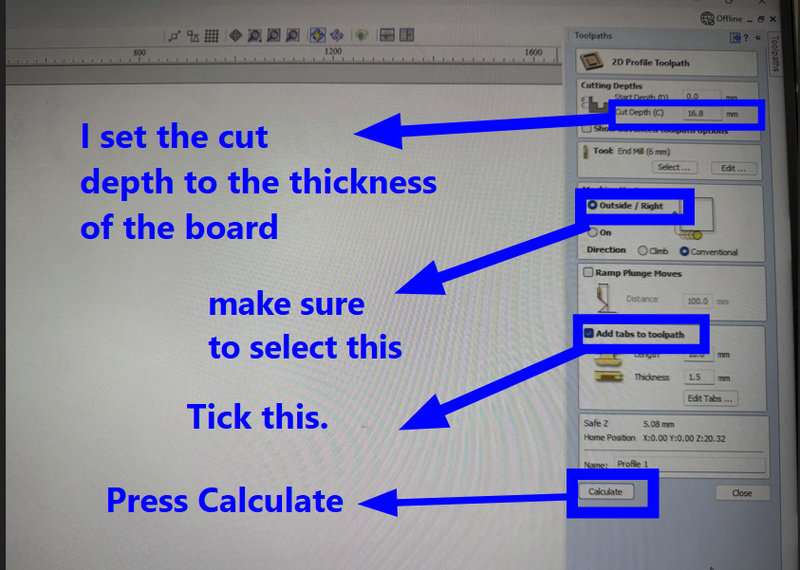
Set Cutting Parameters
- Set cut depth, number of passes, feed rate, and spindle speed.
- For Profile Toolpaths, specify if the cut is inside, outside, or on the line.
And add tabs to the toolpaths. Tabs act as small bridges that hold the pieces in place while the CNC cuts them out of the larger sheet. Without tabs, fully cut pieces could be caught by the spinning tool, which might damage the piece or become a safety hazard.
To create tabs:
- In the toolpath settings, locate the Tabs section and enable Add Tabs to Toolpath.
- Use Edit Tabs to let the software automatically place them or manually click along the cut lines.
- Place tabs strategically where they provide the most support, like corners or long edges.
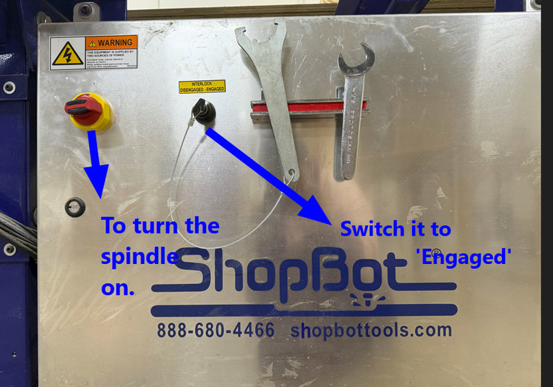
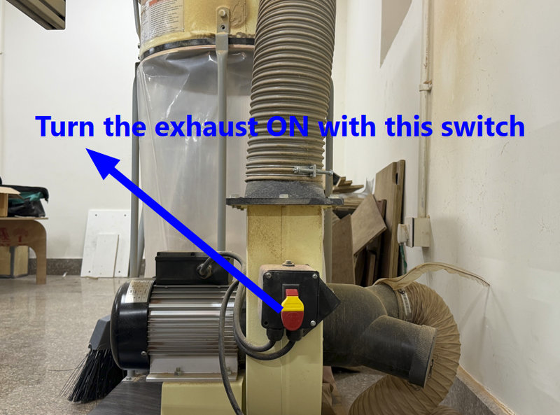
Turning On the Machine and Vacuum
Before starting, I powered on the CNC machine by turning the main switch clockwise. To clear dust and chips, I also turned on the vacuum by lifting its lever upward. This keeps the work area clean and improves safety and visibility.
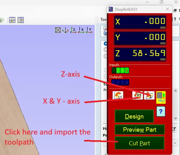
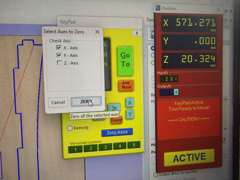
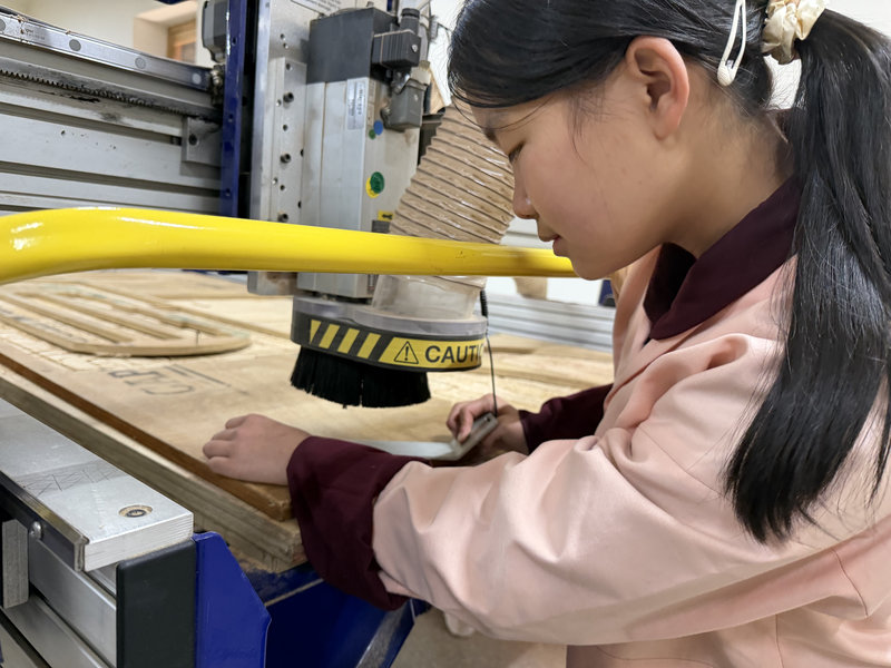
Setting the Machine Origin (X, Y, Z Axes)
- X and Y Axes:Press the button for X-axis zeroing . The machine beeps and positions the X and Y axes automatically. I set the zero point to the lower left corner of my material, which matches the same point in the software.
To set the Z-axis origin (the vertical starting point) on a CNC machine, the machine needs to know exactly where the top surface of your material is. There are two main ways to do this:
- Manual Method: You slowly lower the tool bit by hand until it just touches the material's surface. This physically sets the zero point for Z, so the CNC knows where to start cutting vertically.
- Using a Touch Plate: A touch plate is a small metal plate that acts as a conductor. You place the touch plate on top of your material and attach a clip to the plate, which connects it to the machine. When you press the Z-axis set button, the CNC slowly lowers the tool. As soon as the bit touches the metal plate, it completes an electrical circuit between the bit and the plate. The machine detects this connection and automatically sets that exact height as Z = 0. This method is more precise and consistent than doing it manually, ensuring accurate cutting depths for your project.
- I set the Z origin to the top surface of the material, using a touch plate.. Don't forget to remove the clip afterward.
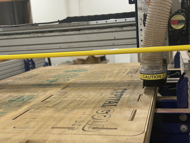
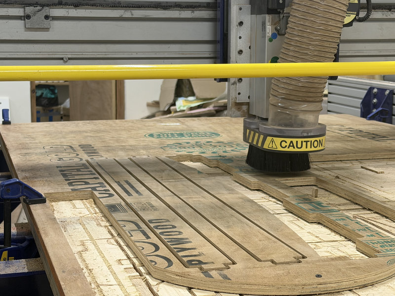
Starting the Cut
Once the clamps were secured and the dust collector was running, I selected Cut Part in the software. A prompt appeared, and I pressed the green Start button followed by OK to begin the milling process.
Emergency Stop (Red Button):
This large red button is designed to instantly shut down the CNC machine if something goes wrong.
It should only be used during emergencies, such as when the tool is cutting incorrectly, a part becomes loose, or there is any safety risk.
When the button is pressed, the machine immediately stops the spindle and all movement of the end mill.
How it works:
- To activate it, press the red button down firmly. This will immediately stop the machine.
- After it is pressed, the machine will remain stopped until the button is reset.
- To reset it, rotate the red button clockwise until it pops back out. Once released, the machine can be restarted.
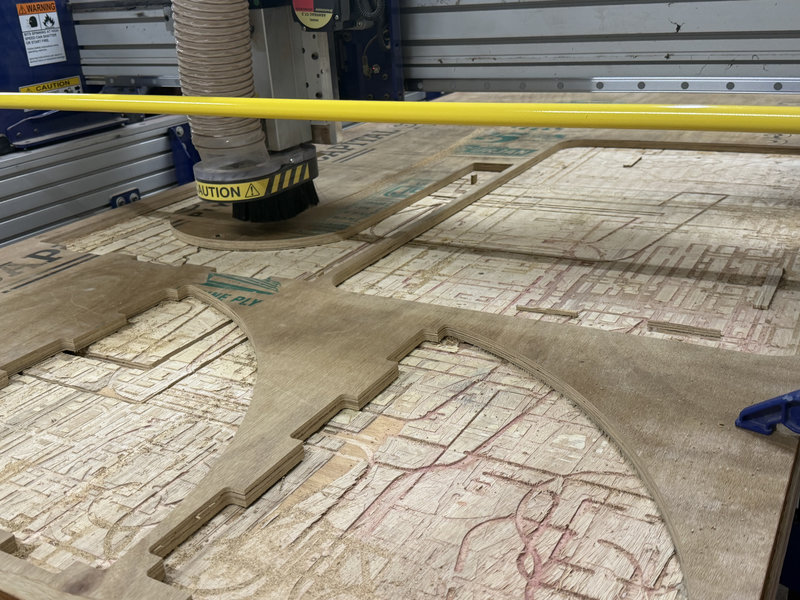
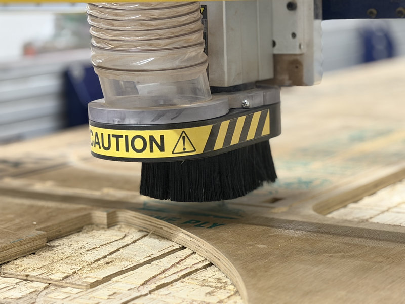
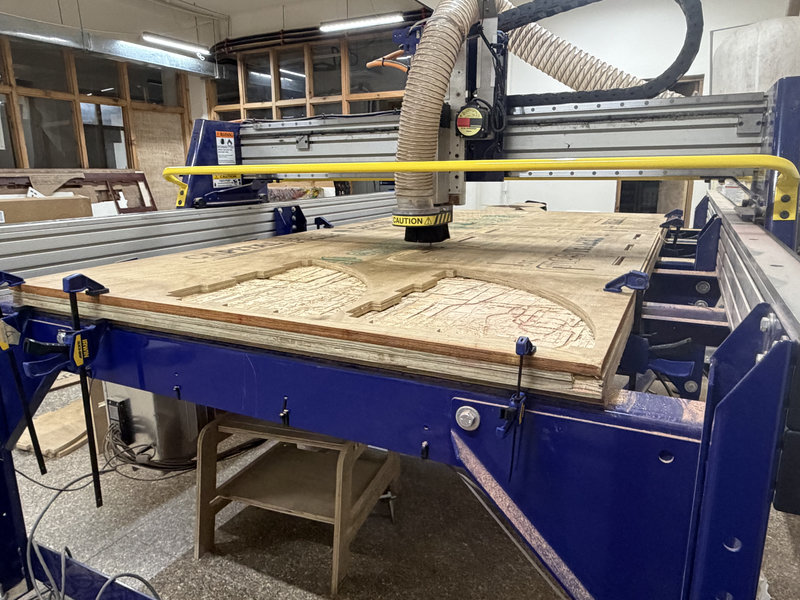
In Process:
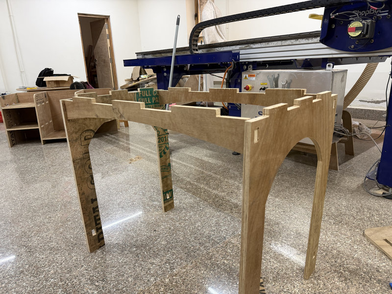
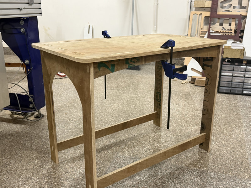
Assembling
Assembling the pieces didn't take long, but it was difficult to get the table to stay rigid and sturdy because some slots turned out a little loose. This happened because I designed the slots using an assumed material thickness of 18 mm. However, the actual plywood thickness varied between approximately 17 mm and 18 mm across the sheet. This difference affected the fit between the parts, making some joints looser than expected. In the future, I would measure the material thickness at multiple points before designing and adjust the thickness and clearance parameters accordingly to achieve a tighter fit.
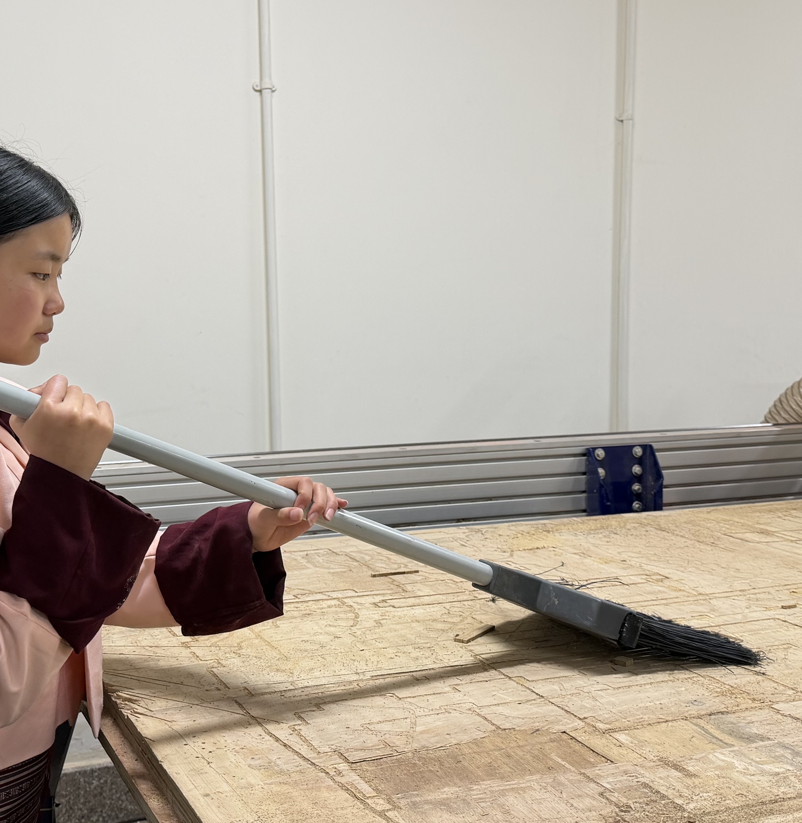
After the cutting process is complete, it is important to clean the CNC bed and remove any remaining wood chips and dust from the machine.
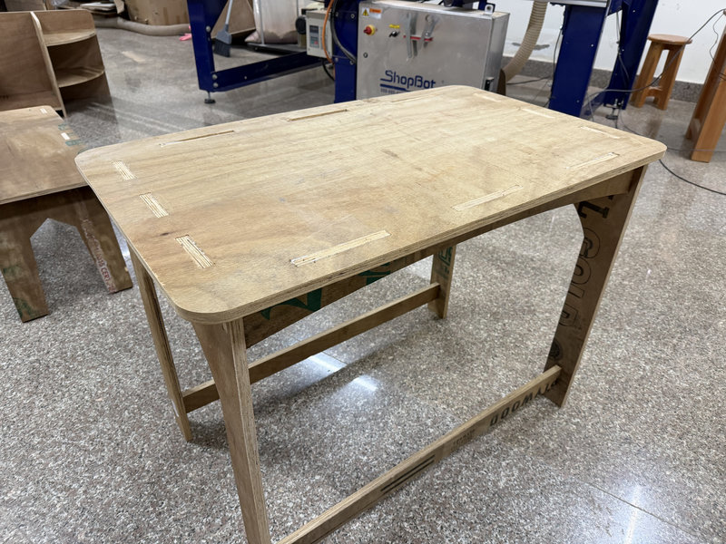
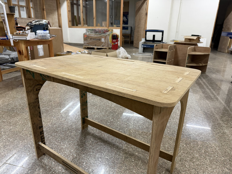
The Results!!
Reflection:
This week was really fun because I got to design my own piece of furniture and assemble it. At first, I felt a bit nervous about using the CNC machine because I had heard many 'things' about it but once I started using it, it was not as intimidating as I expected. Of course, following safety precautions is always very important when working with machines like this.The entire process from preparing the design and generating the toolpath to setting up the machine,was quite long and involved many steps. Because of this, it might be easy to forget some parts of the workflow if the machine is not used regularly. However, I am still very glad that I had the opportunity to learn how to use a CNC machine, as it is a very useful skill for digital fabrication.
Files:
That's all for this week. Thank you! ☆*: .。. o(≧▽≦)o .。.:*☆
- do your lab's safety training
- test runout, alignment, fixturing, speeds, feeds, materials, and toolpaths for your machine
Individual assignment:
- make (design+mill+assemble) something big (~meter-scale)
- extra credit: don't use fasteners or glue
- extra credit: include curved surfaces
- extra credit: use three-axis toolpaths
Learning Outcomes
- Demonstrate the development of a 2D design for CNC milling production.
- Explain the workflow involved in preparing a design for CNC milling.
Here is my schedule for this week:
Group Assignment:
Below is a labelled illustration of the CNC machine used in our lab.
The following diagram shows the axis orientation of the machine, indicating the directions of the X, Y, and Z movements.
You can view the group assignment here.
The CNC machine at our lab is the ShopBot PRS.
- Workspace: 2400mm x 1220mm
- Speed:We used the speed of 10,000 RPM to cut our design
- Software:ShopBot Control Software for operation
- Fixture: Cutting material is attached using clamps
- Setting Origins:We use ShopBot3 software to set the X and Y origins. Proximity sensors are used to detect the edges of the material. For the Z axis, you have to manually set the origin through zeroing — you place a metal zeroing plate on the surface of the material, attach the clip to the end mill, and the machine slowly lowers the bit until it touches the plate to find the exact surface height.
For this assignment, we created a simple design and followed a digital fabrication workflow to produce it using the CNC machine.
The object was designed in Fusion 360 and exported as a DXF file.
The design was then imported into VCarve Pro, where the toolpaths for cutting were created.The material was secured on the CNC bed, and the machine origins (X, Y, Z) were set before starting the job.For the cutting process, we chose a 15 mm thick plywood board.
This was us before starting with the cutting procedure 😆
The wooden piece was secured on the ShopBot workspace using clamps. We used a 6 mm, 2 flute end mill for the operation.
Emergency Stop Button
- Red button: This is the emergency stop button, which will immediately stop the machine when pressed.
- Blue button: This is the reset button, used right after turning on the machine.
- Green button: This is the start button, which makes the end mill begin rotating. Always press this before cutting — if the end mill isn't spinning when the machine starts moving, it will snap.
1. Runout
Runout describes the amount of side-to-side movement of the tool while it is rotating. If the runout is too large, the machine may produce inaccurate cuts, rough surfaces, and the cutting tool may wear out more quickly.
During our safety training, our instructor demonstrated how runout can be checked on the ShopBot machine. The procedure includes:
- Placing a dial indicator against the shank of the end mill (avoiding the cutting edges).
- Slowly turning the spindle by hand while watching the dial indicator to observe any variation in the reading.
For the ShopBot PRS machine, an acceptable runout value is generally below 0.05 mm. If the value is higher than this, it may indicate issues such as a worn collet, dirt inside the collet, or a damaged tool.
Before we began machining, our instructor verified that the runout of the machine was within the acceptable range. We also indirectly confirmed this during our test cut because the profile cuts maintained a consistent width along the entire path, with no noticeable irregularities.
2. Alignment
Proper alignment ensures that the spindle, cutting tool, and material are correctly positioned relative to one another before machining starts. This helps guarantee that the final cut matches the intended design.
To check the alignment of the machine, we followed several steps:
- X and Y Axis Alignment:Using the ShopBot3 software along with the machine's proximity sensors, we located the edges of the material and set accurate X and Y origin points. This ensures that the toolpath corresponds correctly to the actual position of the material on the machine bed.
- Z Axis Alignment:The Z origin was set using the touch plate zeroing method, which allows the machine to detect the exact height of the material surface and cut to the correct depth.
- Material Positioning:The plywood sheet was placed carefully against the corner of the CNC bed before clamping. This helped ensure that the edges of the material were aligned parallel to the machine's axes.
After the machining process was complete, we measured the dimensions of the test piece and found that they matched the original design measurements. This confirmed that the machine was properly aligned during the cutting process.
Safety Guidelines
When operating a CNC machine like the ShopBot PRS Standard, it is important to follow proper safety practices:
- Always wear safety glasses and hearing protection while the machine is running.
- Never leave the machine unattended during operation.
- Keep hands, hair, and clothing away from moving components.
- Use appropriate feed rates and spindle speeds based on the material.
- Make sure the workpiece is securely clamped or fixed before starting the job.
- Regularly inspect the machine for loose parts or wear.
- Avoid wearing loose clothing, and tie back long hair to prevent accidents.
- Keep the emergency stop button within reach in case the machine needs to be stopped quickly.
- After machining, remove any dust or debris from the workspace to keep the machine clean and safe.
Individual Assignment:
CNC Machine
A CNC (Computer Numerical Control) machine is a manufacturing tool operated by computer software rather than manual control. It translates design files (CAD) into precise, automated movements using code to direct drills, or cutters to shape materials like metal, wood, or plastic with high speed and accuracy.
For this week’s assignment, which involves designing, milling, and assembling something large, I decided to create a simple piece of furniture that is also useful. After choosing between a table and a mini bookshelf, I decided to make a table since the assignment requires the furniture to be at a meter scale size.
To deisgn the table, I used the software Fusion 360 since I was more familiar with that software.
I started my design by defining parameters for dimensions that I would use a lot, like the thickness of the material. Since the exact thickness wasn’t confirmed at the beginning of the week, I temporarily set it to 18 mm. This way, I could easily adjust the parameter later if the material thickness needed to be changed.
To add and modify parameters, navigate to 'Modify' and from the dropdown, choose 'Change Parameters'
Then, click on the plus sign to add new parameters and enter the required values, such as the measurement and the name of the parameter, which can also be written as text.
These were all the parameters I've used for my design:
Next, I began by creating a sketch of the base of the table. I used the Center Rectangle tool to draw the rectangles and set the dimensions using the pre-defined parameters for the height and length.
Then I extruded the sketch of the tabletop and used the thickness parameter to set the depth of the tabletop.
Then, I created the table legs by sketching them in a similar way as the tabletop. I set the width of each leg to match the breadth of the tabletop, which was 60 cm, and used the height parameter of 72 cm for the legs.
After that, I used the Arc tool to sketch a curve on the leg and removed that section while extruding to shape the leg.
Then mirror the leg using the mirror tool
Next, I created slots for each leg. I added two slots on every leg, each measuring 150 mm by the material thickness..
Opps 🤦♀️ turns out 150mm for the slot width was a bit too, long. So I changed the slot width parameter to 90mm instead.
Then extrude the slots, and set the height of the slot to the thickness of the material using the thickness parameter:
After that, I sketched the slots on the tabletop, positioning them carefully so that when I cut out the sketch, the legs would slide into the slots properly.
I repeated the same process for the other leg and then sketched the table stretcher using parameters to provide extra support.I wanted the stretcher to have a curved feature, so I used the 3 point arc tool to draw a curve on the stretcher and extruded the arc out.
I mirrored the arc to the other side and then created slots for the stretcher as well with two slots for the tabletop and one slot on each end of the stretcher to connect to the legs.
I used the Fillet tool to round off the corners of the tabletop, to make them look smooth and more finished:
Next, I added the bottom supports connecting the two legs. Similar to the stretcher, I sketched the bottom support using the 2 point Rectangle tool, with the length extending from one edge of the leg to the other and a width of 60 mm.
Dogbones:
Next, I added dogbone fillets to the design to ensure the parts could be cut accurately with the CNC machine. Dogbones are small circular cutouts added to the inside corners of slots. Since CNC milling bits are round, they cannot create perfectly sharp internal corners. By adding dogbones, extra space is created in the corners, allowing the rectangular parts to fit together properly after milling. This helps ensure that the joints slide together smoothly during assembly.I followed azhim Tsheltrim's week 7 assignment page to add dogbones:
Download dogbone addin for fusion from here
Steps for Adding the Dogbone Addin in Fusion:
- Start by downloading the Dogbone addin from the link and extracting the downloaded file.
- After extraction, rename the folder Dogbone_master to simply Dogbone, then copy this folder.
- Open the Run window by pressing Win + R, type %appdata%, and press Enter.
- In the folder that opens, go to Roaming → Autodesk → Autodesk Fusion 360 → API → AddIns.
- Paste the copied Dogbone folder inside the AddIns folder.
- Launch Fusion 360.
- Navigate to Utilities, then open AddIns tab.
- Look for Dogbone in the list of available addins.
- Turn on Run on Startup so the add-in loads automatically whenever Fusion starts.
- Finally, press Run to enable the Dogbone add-in.
Use the dogbone addin for your deisgn for slot holes and the sides of the finger slots:
And it sort of does look like a cartoon dogbone 😃
This is the final result of my table design:
I uploaded the deisgn to sketchfab as well:
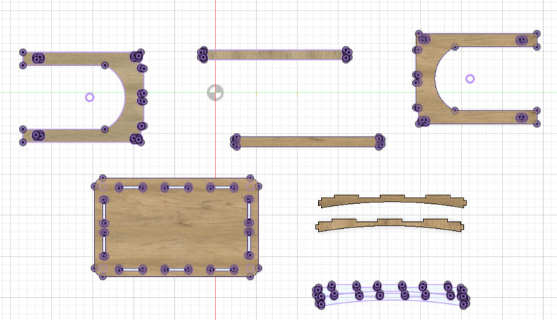
Before we begin milling the design, we need to export the 3D model as a DXF file. Similar to how laser cutters use DXF files or 3D printers use G-code, a DXF file acts like a language that the CNC machine can understand. This step translates our digital design into instructions that the machine can follow to accurately cut and shape the material.
- Arrange all the components of your design by placing them one by one.
- Click on Create Sketch and select the horizontal plane. Press P to use the Project tool. Then click on each component to project its outline onto the sketch. You should see a purple sketch appear on each component, showing the projected geometry.Since the CNC machine follows 2D vector paths, we only need the sketches for exporting. Projecting the components allows us to capture their outlines accurately.
- Once all the sketches are projected, a new sketch will appear in the browser panel containing all the projected outlines. Select this sketch, click Export, and choose the DXF file format.
Milling Process:
Loading and Securing the Material
First, I placed the wood on the CNC bed. To keep it from moving during cutting, I set the clamps carefully. Properly clamping the board is really important for both safety and accuracy, ensuring the material stays stable for precise milling.
Generating a Toolpath in VCarve Pro
CNC toolpaths are the specific, programmed routes a cutting tool follows to remove material and create a part, acting as a "roadmap" for the machine. They are created in CAM software and control the tool's movement, speed, and depth — all converted into G-code that the CNC machine understands.
Vcarve
I used VCarve Pro 11.0 to generate the toolpaths for my design. VCarve Pro is a powerful, user friendly CAD/CAM software suite developed by Vectri. The software is a complete software solution for CNC routing, sign making and engraving. This is the software many professional sign shops and fabricators use. While the software can import your designs from other programs, it also contains a complete all the tools needed to create your designs right in the program.
Open the software and select 'New File'.
I updated the page dimensions in the software to match the real size of my board and entered the material thickness.Then import your design file by naviagting to 'Import' and select 'Import Vector files'
Next, I selected the imported design and organized the components to minimize material waste.Make sure nothing overlaps and that spacing is sufficient for the cutting tool.
-
Select the Toolpath Type
- Click on the Toolpaths tab.
- Choose the type of toolpath depending on your operation:
- Profile Toolpath: For cutting along the outline of a part.
- Pocket Toolpath:For clearing out areas inside a shape.
- V-Carve Toolpath:For engraving or detailed designs.
-
Choose Your Tool
- Select the appropriate cutting tool (end mill, ball nose, V-bit) based on your design.
- Input the tool dimensions like diameter, tip angle, etc to cut accurately.
-
Set Cutting Parameters
- Set cut depth, number of passes, feed rate, and spindle speed.
- For Profile Toolpaths, specify if the cut is inside, outside, or on the line.
This was the toolpath for my design:
And add tabs to the toolpaths. Tabs act as small bridges that hold the pieces in place while the CNC cuts them out of the larger sheet. Without tabs, fully cut pieces could be caught by the spinning tool, which might damage the piece or become a safety hazard.
To create tabs:
- In the toolpath settings, locate the Tabs section and enable Add Tabs to Toolpath.
- Use Edit Tabs to let the software automatically place them or manually click along the cut lines.
- Place tabs strategically where they provide the most support, like corners or long edges.
Turning On the Machine and Vacuum
Before starting, I powered on the CNC machine by turning the main switch clockwise. To clear dust and chips, I also turned on the vacuum by lifting its lever upward. This keeps the work area clean and improves safety and visibility.
Setting the Machine Origin (X, Y, Z Axes)
- X and Y Axes:Press the button for X-axis zeroing . The machine beeps and positions the X and Y axes automatically. I set the zero point to the lower left corner of my material, which matches the same point in the software.
- Manual Method: You slowly lower the tool bit by hand until it just touches the material's surface. This physically sets the zero point for Z, so the CNC knows where to start cutting vertically.
- Using a Touch Plate: A touch plate is a small metal plate that acts as a conductor. You place the touch plate on top of your material and attach a clip to the plate, which connects it to the machine. When you press the Z-axis set button, the CNC slowly lowers the tool. As soon as the bit touches the metal plate, it completes an electrical circuit between the bit and the plate. The machine detects this connection and automatically sets that exact height as Z = 0. This method is more precise and consistent than doing it manually, ensuring accurate cutting depths for your project.
- I set the Z origin to the top surface of the material, using a touch plate.. Don't forget to remove the clip afterward.
To set the Z-axis origin (the vertical starting point) on a CNC machine, the machine needs to know exactly where the top surface of your material is. There are two main ways to do this:
Starting the Cut
Once the clamps were secured and the dust collector was running, I selected Cut Part in the software. A prompt appeared, and I pressed the green Start button followed by OK to begin the milling process.
Emergency Stop (Red Button):
This large red button is designed to instantly shut down the CNC machine if something goes wrong.
It should only be used during emergencies, such as when the tool is cutting incorrectly, a part becomes loose, or there is any safety risk.
When the button is pressed, the machine immediately stops the spindle and all movement of the end mill.
How it works:
- To activate it, press the red button down firmly. This will immediately stop the machine.
- After it is pressed, the machine will remain stopped until the button is reset.
- To reset it, rotate the red button clockwise until it pops back out. Once released, the machine can be restarted.
In Process:
Assembling
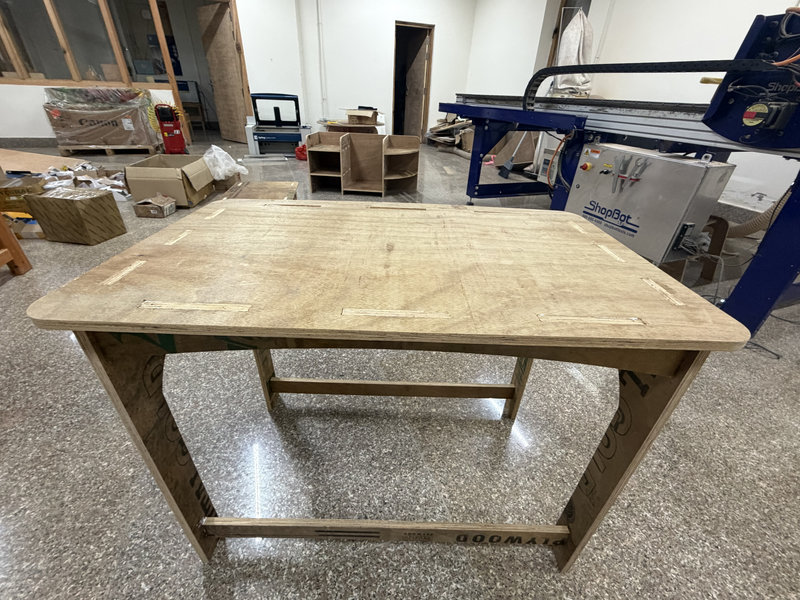
Assembling the pieces didn't take long, but it was difficult to get the table to stay rigid and sturdy because some slots turned out a little loose. This happened because I designed the slots using an assumed material thickness of 18 mm. However, the actual plywood thickness varied between approximately 17 mm and 18 mm across the sheet. This difference affected the fit between the parts, making some joints looser than expected. In the future, I would measure the material thickness at multiple points before designing and adjust the thickness and clearance parameters accordingly to achieve a tighter fit.
After the cutting process is complete, it is important to clean the CNC bed and remove any remaining wood chips and dust from the machine.
The Results!!
Reflection:
This week was really fun because I got to design my own piece of furniture and assemble it. At first, I felt a bit nervous about using the CNC machine because I had heard many 'things' about it but once I started using it, it was not as intimidating as I expected. Of course, following safety precautions is always very important when working with machines like this.The entire process from preparing the design and generating the toolpath to setting up the machine,was quite long and involved many steps. Because of this, it might be easy to forget some parts of the workflow if the machine is not used regularly. However, I am still very glad that I had the opportunity to learn how to use a CNC machine, as it is a very useful skill for digital fabrication.
Files:
That's all for this week. Thank you! ☆*: .。. o(≧▽≦)o .。.:*☆