Week 5: 3D Scanning and Printing
Group assignment:
- test the design rules for your 3D printer(s)
Individual assignment:
- design, document, and 3D print an object that could not be made subtractively (small, few cm3, limited by printer time)
- 3D scan an object (and optionally print it)
Learning Outcomes
- Understand the main advantages and limitations of 3D printing and how these affect the final printed result.
- Apply basic design methods and manufacturing processes to show an understanding of how 3D printing is used in practice.
- Demonstrate how 3D scanning can be used to turn physical objects into digital models for printing or modification.
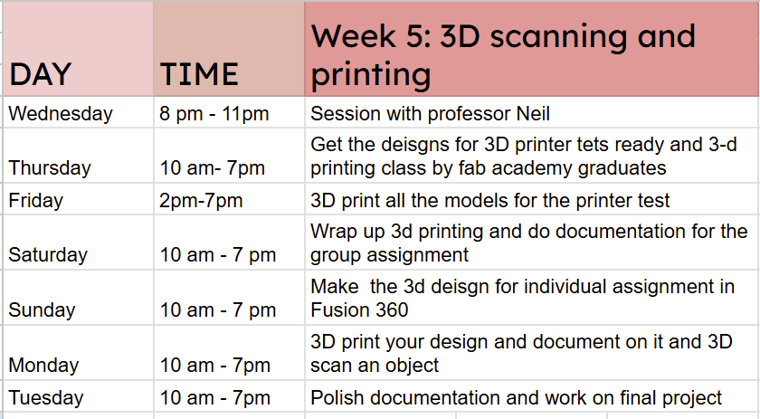
As usual, I planned my week out with a schedule:
Group Assignment
This week's group assignment focused on characterizing the design rules of our 3D printer by printing test models. Each model was designed to evaluate specific features and limitations of the machine, including overhang performance, bridging capability, hole accuracy, and general print precision. All tests were carried out using the Prusa i3 MK3 available in our lab. You can access the group assignment here.
Here is a labelled diagram of the Prusa i3 MK3 Printer:
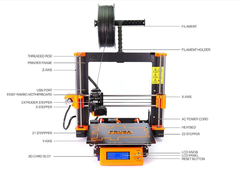 Image source
The table below outlines the key technical specifications of the Prusa i3 MK3S. This information is sourced from this site.
| Specification | Details |
|---|---|
| Technology | Fused Deposition Modeling (FDM) |
| Build Volume | 250 × 210 × 210 mm |
| Layer Height | 0.05 – 0.35 mm |
| Nozzle Diameter | 0.4 mm (default); other sizes supported |
| Max Nozzle Temperature | 300 °C |
| Max Bed Temperature | 120 °C |
| Max Travel Speed | 200+ mm/s |
| Filament Diameter | 1.75 mm |
| Extruder Type | Direct drive with Bondtech gears and E3D V6 hotend |
| Mainboard | Einsy RAMBo 8-bit with Trinamic TMC2130 drivers |
| Print Surface | Magnetic heatbed with removable PEI spring steel sheet |
| Bed Leveling | Automatic Mesh Bed Leveling via SuperPINDA probe |
| Filament Sensor | Yes, IR-based |
| Power Panic | Yes, hardware-based |
| Connectivity | SD card and USB |
| Display | Monochromatic LCD |
| Power Supply | 240W custom Delta PSU |
| Printer Dimensions | 50 × 55 × 40 cm |
| Weight | 7 kg |
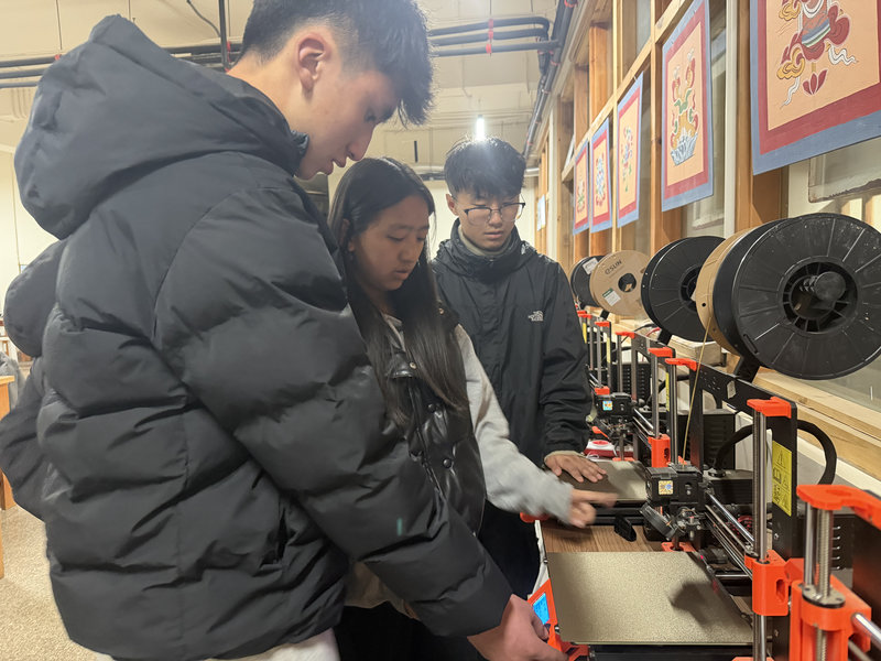
This week, the 2024 Fab Academy graduates guided us on how to use the 3D printer. A big thanks to them for taking the time to teach and help us!
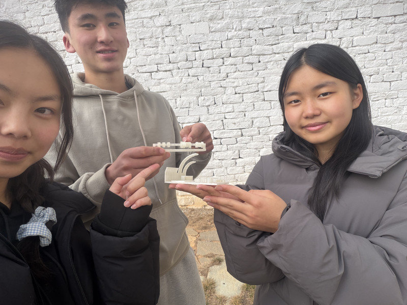
This is me and my team after printing out the models 😆
By observing the print results, we were able to better understand how the printer handles challenging geometries and which design considerations are important for achieving reliable prints. For instance, we understood that:
- Hole test: The printer holes were reasonably printed well, without excess filament.
Conclusion: the printer is reasonably good in printing holes close to the intended measurement. - Diameter test: The cylinders were printed nicely as well.
Conclusion: the printer is reasonably good in printing circles close to the intended measurement. - Vertical pillar test: As the pillar height increased, the filament deposition appeared less stable especially for the 30 mm pillar.
Conclusion: The results showed slight inconsistencies, suggesting that better calibration is needed. - Bridge test: As the bridge length increased, the print became more unstable and slightly shaky. The 5 mm and 10 mm bridges broke during printing, because of temperature issues and the structure itself being weak and fragile.
Conclusion: Bridges, which print filament between two points without support underneath, can be unstable. Adding supports may be necessary to ensure they print successfully. - Clearance: As the gap between the block and the rod decreased, the block moved less freely. At a 0.2 mm gap, it could barely move, while at 0.1 mm it was completely stuck.
Conclusion: To ensure printed parts can move freely, a minimum gap of 0.3 mm is recommended for designs.
Overall, the group assignment was really fun, especially it being my first time using a 3D printer and printing something and I learned how important it is to understand a machine's capabilities and limitations, to get accurate and high quality prints.
Individual assignment:
For the individual assignment, we had to design and 3D print something that could not be made subtractively.
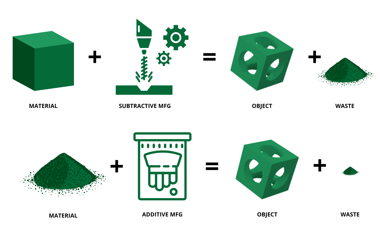
Additive Manufacturing: Making objects by adding material layer by layer, like 3D printing.
Pros: Can make complex shapes, less material waste and quick prototyping.
Cons: Slower for large parts and limited material strength.
Subtractive Manufacturing: Making objects by removing material from a solid block, like CNC milling or laser cutting.
Pros: Stronger parts, smooth surface finish and precise dimensions.
Cons: Material waste, harder to make complex shapes and setup can be time consuming.
I decided to make the Ball in Cage design. The design was made in Fusion 360, starting with the outer cage. A 50mm cube was created by sketching a 50 mm square in the sketch workplace and extruding it. It is the main structure of the cage. Then, I set the thickness of the cube to 4mm using the Shell tool. To create the cage windows, 42mm squares were sketched on each face of the cube and cut through using the Extrude tool set to Cut, which hollowed out the openings and left a thick frame around each face giving it that classic cage look.
.png)
.png)
.png)
.png)
.png)
Next the ball was created using the Sphere tool, set to a diameter of 40 mm. This size was chosen carefully, big enough to stay trapped inside the cage but small enough to move around freely without escaping through the 42mm windows. The sphere was then placed inside the cage and centered using the Move and Align tools so it had equal space on all sides.
.png)
.png)
A basic design for the ball in cage was done.
.png )
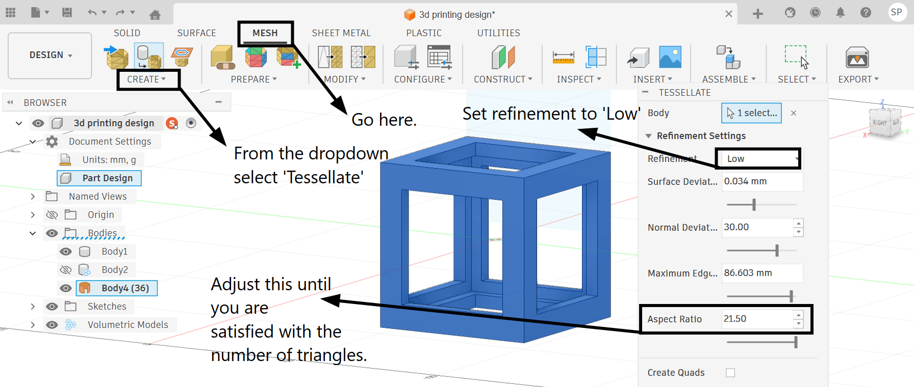
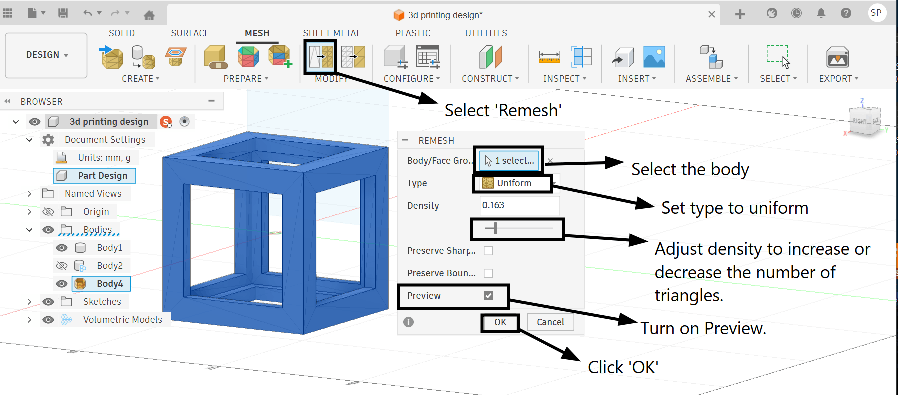
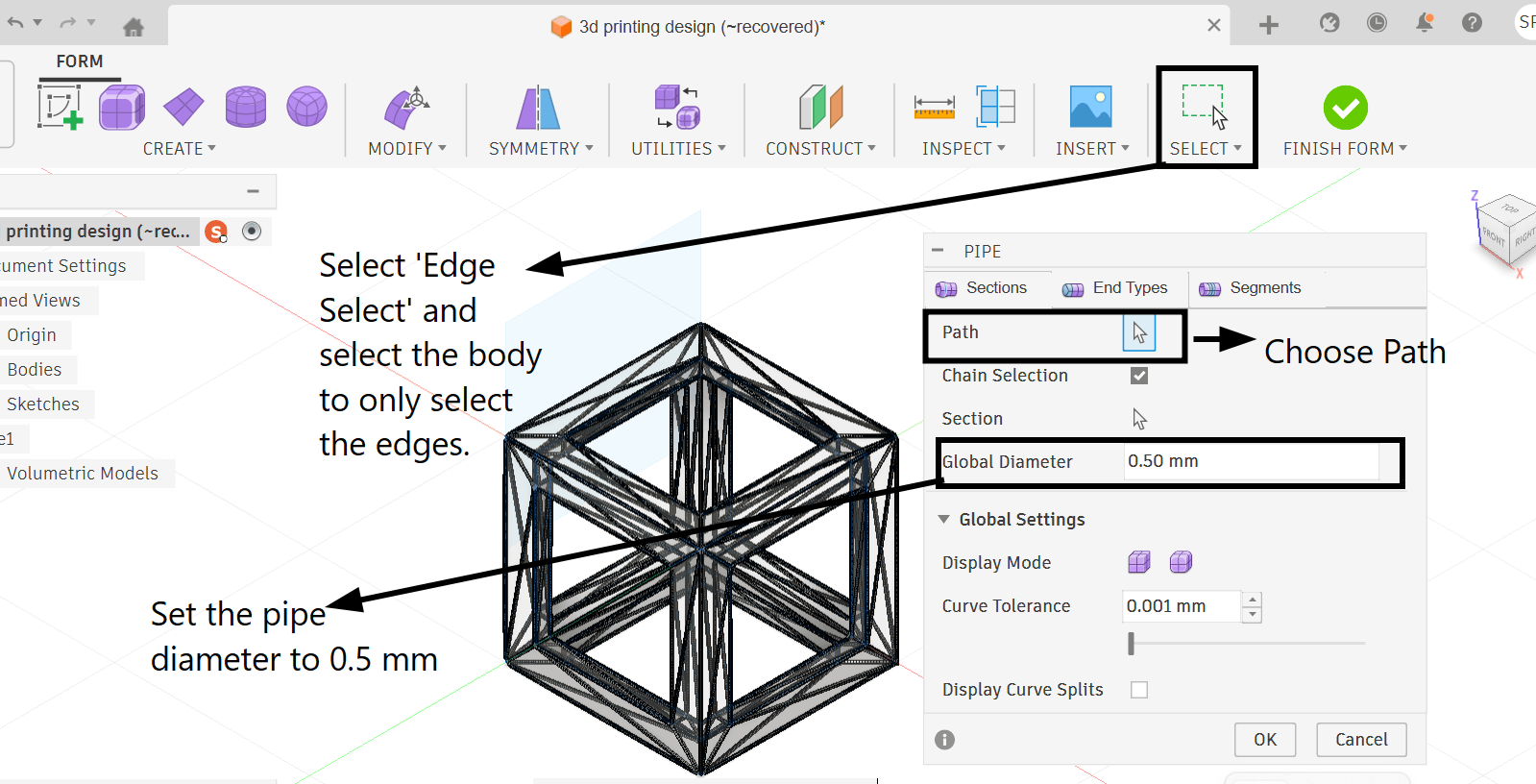
To make the sphere look more interesting, the Volumetric Lattice add-in was applied to it from the Mesh workspace. This gave the sphere an open lattice pattern with holes going through it, and the Solidify setting was adjusted to make sure the struts were thick enough to actually be printable. The cage was also given a cool geometric look by using the Tessellate tool which broke the smooth surfaces down into a triangular faceted pattern, giving it a low-poly diamond-like appearance.
I even tried to make the cube structure out of pipes, but I couldn't finish the form since there were a lot of self intersecting edges that caused the software to malfunction and crash a couple dozen times.
However, the additional design features did not transfer correctly into PrusaSlicer, so I proceeded using the basic version instead.
.jpg)
Generating G-Code:
G-code is a standardized numerical control programming language used in 3D printing to instruct the printer's hardware on every physical action required during a print, including print head movement coordinates, print speed, extrusion amount, and temperature settings. It is automatically generated by slicer software from a 3D model and read directly by the printer during the printing process.
I used the PrusaSlicer software to generate my G-code for my model. PrusaSlicer provides an intuitive workspace for preparing 3D prints. The central area shows a 3D view of the model, making it easy to move, rotate, and scale objects. The top toolbar allows adding or removing models, while the side panels include tools for adjusting the design and selecting settings for the printer, filament, and print profile. Users can also choose options like supports, brims, or skirts.
.jpg)
Once the model is ready, pressing the "Slice now" button converts it into G-code, which can be saved or sent straight to a printer. Additional settings for fine control, such as layer height, infill, and temperature, can be accessed by switching to Advanced or Expert mode. With its clear layout and wide range of options, PrusaSlicer is a preferred tool for both beginners and experienced users to optimize their 3D prints.
Set the following parameters in PrusaSlicer before generating G-code:
- Quality / Speed: Balance between print quality and printing speed. Higher quality prints take longer to complete. In PrusaSlicer, this can be selected using preset profiles such as 0.10mm DETAIL, 0.20mm QUALITY, or 0.30mm DRAFT.
- Print Settings: Configure parameters like layer height, shell thickness, number of perimeters, and print temperature for optimal results. PrusaSlicer allows fine-tuning these under the Print Settings tab.
- Material Selection: Choose the appropriate filament type (e.g., PLA, PETG, ABS) based on the project's requirements and printer compatibility. In PrusaSlicer, filament profiles can be selected under the Filament Settings tab to automatically apply the correct temperature and speed for the chosen material.
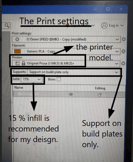
- Printer Selection: Ensure the correct Prusa printer model is selected (e.g., Prusa MK4, MK3S+) to match the slicing settings with the printer's capabilities. This is configured under the Printer Settings tab in PrusaSlicer.
- Infill: Determine the density and pattern of the internal structure of the print, affecting strength and material usage. PrusaSlicer offers various infill patterns such as Grid, Gyroid, and Honeycomb, with density typically ranging from 10% to 100%. For most standard prints, an infill of 15% is commonly recommended as it provides a good balance between structural integrity, material efficiency, and print time. The majority of general purpose designs such as decorative models, enclosures, and low-stress components print well at this density without requiring excessive filament or time. However, infill percentage should always be decided based on the specific requirements of the design.
- Supports: Enable support structures if the model contains overhanging areas that cannot be printed without assistance. PrusaSlicer can generate supports automatically or allow manual placement.
For the support, I used it only for my base plate because if supports were placed everywhere, they would have generated inside the cage around the ball which would have been much more difficult to remove after printing since it's harder to reach inside the cage to break them off.
.jpg)
- Export G-code: Once all settings are configured, slice the model and export the G-code file to an SD card or USB drive to transfer it to the Prusa printer for printing.
 (1).jpg)
 (1).jpg)
Why the Default Infill in PrusaSlicer is 15%
15% is the most practical and balanced starting point for the majority of everyday 3D prints.
- Prusa Research determined through extensive testing that 15% provides adequate internal support for outer walls, preventing them from collapsing or warping during printing.
- It avoids unnecessary filament waste and does not add extra print time.
- The internal grid structure at 15% is strong enough to hold the model's shape, support top layers from sagging, and handle light everyday use.
- Going lower than 15% risks producing fragile prints with poorly supported surfaces.
- Going higher than 15% for general prints simply uses more material and time without a meaningful benefit for most designs.
Overall, 15% works well for most users, most designs, and most situations, making it a safe and reliable default that can be adjusted based on the specific needs of each print.
For this design, the infill was kept at 15% because it was enough to keep the model sturdy without wasting filament or adding extra print time, since the model is decorative and does not need to be completely solid.
Eject SD Card
Ejecting the SD card before physically removing it ensures that all data has been fully written and saved onto the card. When you slice and export your G-code in PrusaSlicer, the computer may still be finishing up background write processes even after the file appears saved.
To eject the SD card, navigate to the system tray located at the bottom right of the taskbar and click the upward arrow icon to reveal hidden icons. From the popup, click on the removable devices icon (which resembles a USB drive) and select the name of your SD card from the list. A notification will then appear on screen confirming that the SD card is safe to remove.
.jpg)
Printing Procedure:
Once the SD card is inserted into the Prusa printer, select "Print from SD card" since that's where we stored our G-code file.
.jpg)
Next, navigate through the printer's menu to locate and select your G-code file from the list of saved designs on the SD card.
.jpg)
Printing Speed Adjustment:
The print was started at 20% of the printer's maximum speed to prioritize stability and surface quality, particularly for the sphere's base and the cage structure. Once the print showed consistent adhesion and steady layering, the speed was carefully raised to 30%.
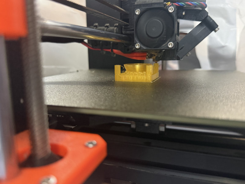
Print Quality Issues Due to Lab Environment
Due to the cold temperature and humidity of the lab, the printer began producing wobbly filaments and printing the design inaccurately after running for some time. The cold environment was causing inconsistent filament flow and poor print quality.
Failed attempts:
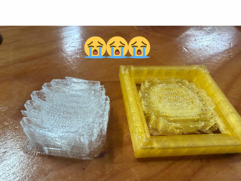
After multiple attempts at adjusting the printer settings with no success, we covered the printer with a plastic bag to trap heat and maintain a more stable temperature around the machine.
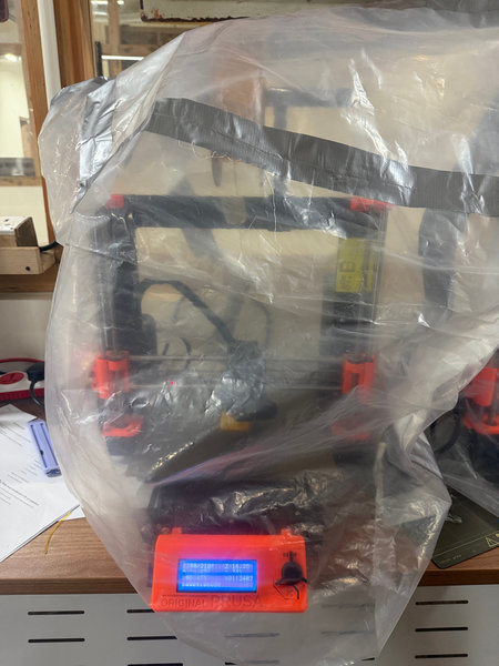
Printing Started:
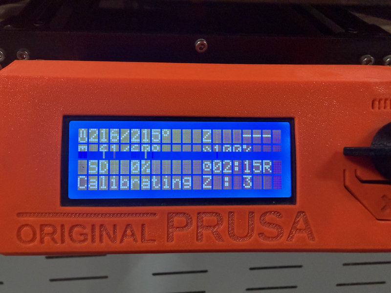
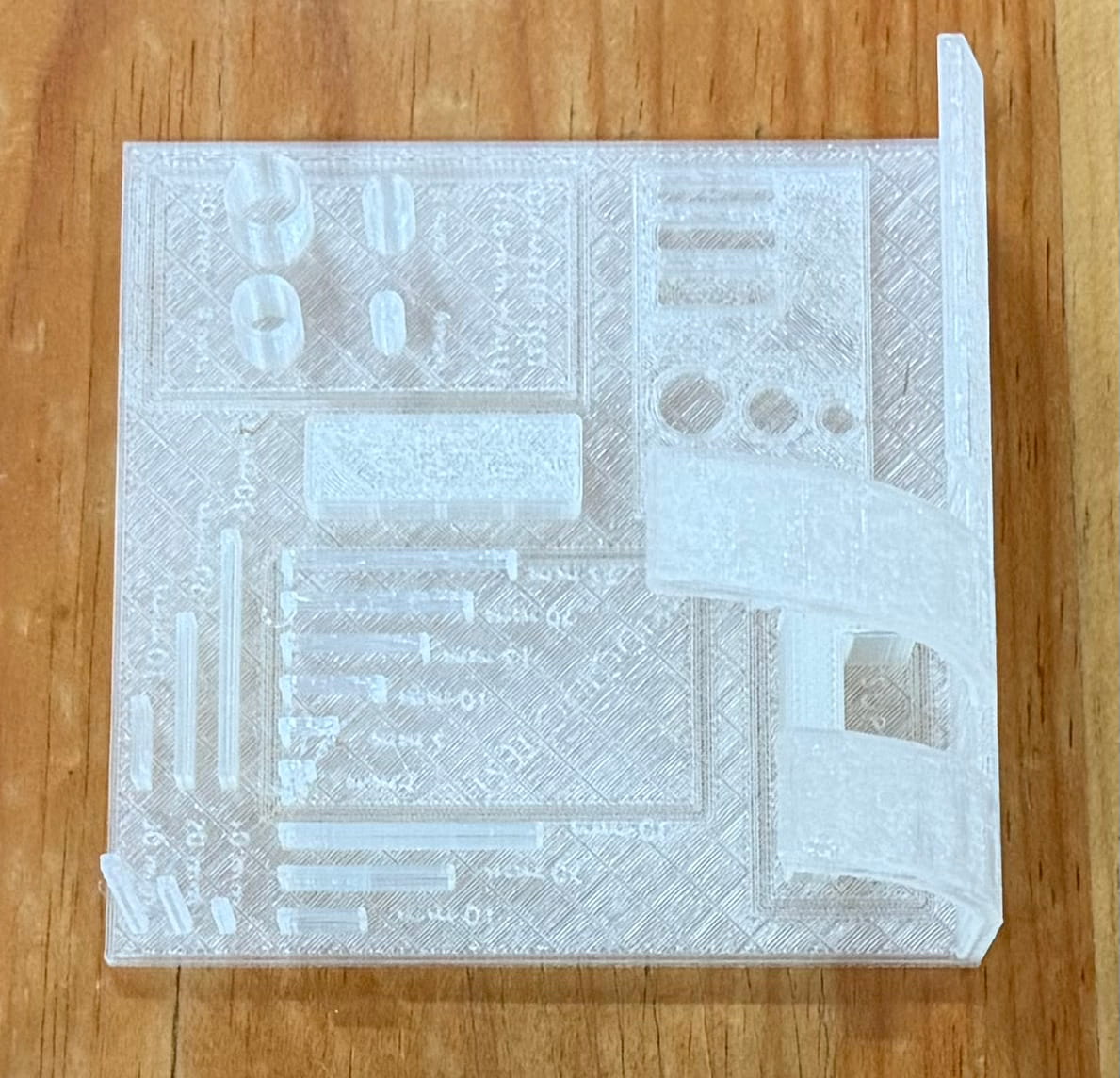
The Results
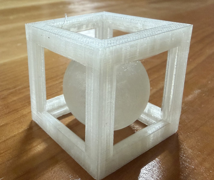
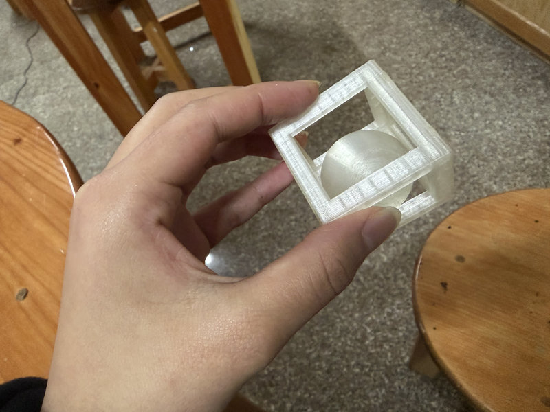
The 3D Model:
The ball in a cage design cannot be made subtractively because the ball is fully enclosed inside the cage with no entry point for any cutting tool to reach it. In subtractive manufacturing, material is cut away from a solid block, but there is no way to carve out the interior of the cage and shape the ball inside it at the same time without cutting through the cage walls, which would destroy the design entirely.
3D Scanning
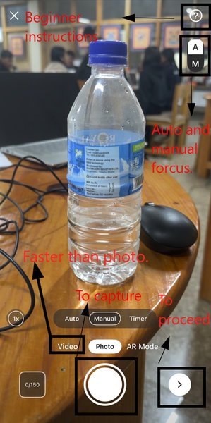
For 3D scanning, I used Kiri Engine. I installed the app directly on my phone from the App Store to begin scanning objects.

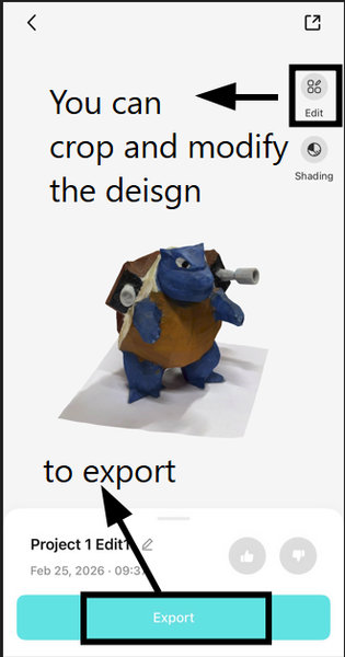
Kiri Engine is a 3D scanning application that uses photogrammetry to convert real world objects into 3D digital models. It works by taking multiple photos of an object from different angles and then stitching them together to generate a 3D mesh. The app is straightforward to use and accessible since it runs directly on a smartphone, making it a practical tool for quickly capturing real objects and importing them into 3D modeling software like Fusion 360 for further editing or 3D printing.
I scanned a 3D turtle model I found in the lab using the app.
Scanning Process
To create a 3D scan using Kiri Engine, I captured a total of 150 photos. For the first 75 images, I held the device steady and went around the model slowly clockwise, making sure to cover the top and eye level views thoroughly. For the remaining 75 images, I went around it counterclockwise, focusing on capturing the underside of the model.
I also scanned my LEGO spaceship as a small extra test. This was just done for fun ╰(*°▽°*)╯
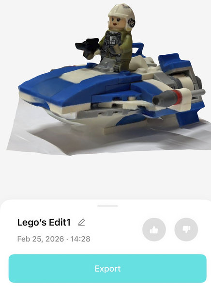
The scan turned out decent overall, but it did not look completely realistic. Some areas, especially around the bottom of the model, had missing patches. The texture quality was also not perfect, instead of appearing smooth and glossy like real plastic, it looked slightly distorted and smudged. These imperfections likely occurred because shiny surfaces such as plastic can be difficult for scanning software to capture accurately. Reflective materials tend to confuse the camera's ability to detect consistent features. Additionally, the LEGO spaceship contained many small and detailed parts, which can make it harder for the scanner to reconstruct the geometry cleanly.
Reflections:
This week was a lot of fun, especially the exciting feeling of printing your own model on a 3D printer for the first time!
Files:
LEGO spaceship 3D scan on Sketchfab
Ball in Cage design in Fusion 360
That's all for this week, thank you! ✨