Week 4: Embedded Programming
Just like the previous weeks, we had to do a group assignment along with our individual assignments.
Group Assignment
- Demonstrate and compare the toolchains and development workflows for available embedded architectures.
Individual Assignment
- Browse through the datasheet for a microcontroller.
- Write and test a program for an embedded system using a microcontroller to interact (with input &/or output devices) and communicate (with wired or wireless connections).
- Extra credit: Assemble the system.
- Extra credit: Try different languages &/or development environments.
Just like the recent week, I've started my week by planning out my schedule:
.jpg)
This week was more about me trying to comprehend all the new words that were thrown at me, so this page might be longer than usual because of all attempts to trying to explain things. First up, let's understand what an embedded system really is.
Group Assignment
For this week's group assignment, we compared the toolchains and development workflows of the embedded architectures available in our lab. We evaluated 3 different boards, which included the XIAO ESP32 C3, Arduino Uno, and an ATtiny 44 board.
To understand the differences in setup and programming, we uploaded simple blink sketches to each board. We divided the tasks among our group so that each of us could test a specific board. I worked with the Arduino Uno, which we selected because it is one of the most widely used microcontroller boards. Through this comparison, I learned that different microcontrollers require different setup processes. For example, some boards include a built-in LED that can be used directly for blink tests, while others require connecting an external LED. This highlighted how hardware features and configurations vary across architectures. You can find the detailed documentation on our group's work here:
Week 4 Group Assignment - Embedded ProgrammingEmbedded System
A computer (has a processor, memory, and runs code) built into a device to perform one specific task, running a single program permanently stored in memory. Unlike a laptop, it has no keyboard or screen; it just runs. Examples include the microcontroller inside a washing machine or the chip in a traffic light.
Key distinctions:
- Internal vs. External: Internal lives inside (microwave); External is a separate unit (Raspberry Pi).
- Special vs. General Purpose: Special does one job (smoke detector); General can run many programs (laptop).
Binary
Binary is the numbering system that makes digital signals useful. Computers represent all information using only 1s and 0s. A single 1 or 0 is called a bit. Eight bits grouped together is called a byte.
| Bit Position | 8 | 7 | 6 | 5 | 4 | 3 | 2 | 1 | = Value |
|---|---|---|---|---|---|---|---|---|---|
| Power of 2 | 128 | 64 | 32 | 16 | 8 | 4 | 2 | 1 | - |
| All 1s | 1 | 1 | 1 | 1 | 1 | 1 | 1 | 1 | 255 |
| Number 10 | 0 | 0 | 0 | 0 | 1 | 0 | 1 | 0 | 10 |
Digital vs Analog Signals
Digital Signal
A signal that can only be one of two values: high (1) or low (0), voltage present or no voltage. No "in between", no gradual change. It is either on or off. This is the language computers and microcontrollers naturally speak, everything inside a chip is binary. A button press, an LED state, a logic output, these are all digital signals.
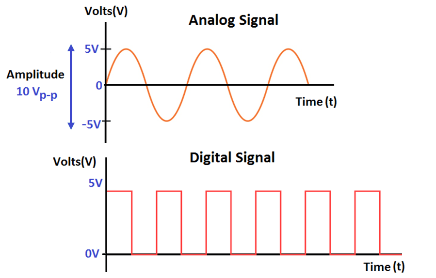
Analog Signal
A continuous signal that can be any value within a range. It flows and varies smoothly with no steps or jumps. The physical world is entirely analog: temperature doesn't jump instantly from 20°C to 21°C, it rises gradually through every value in between. A microphone output, a temperature sensor voltage, a light sensor, all produce analog signals. On a microcontroller, analog signals are read through the ADC pins.
This is how I think about it, a digital signal can only ever be 0 or 1. Nothing in between.
An analog signal can be 0, 0.1, 0.5, 0.75, 1.3, 2.7 —
This image right here shows that analog signals vary continuously and smoothly across a range of values, like a wave that can rise and fall to any point. Digital signals exist only as discrete states — either 0 or 1, with nothing in between.
Browsing through the Datasheet
ESP32
The microcontroller I plan on using for my final project is the Xaio ESP32 C3.
.jpg)
Here is the link to the datasheet of ESP32 C3.
Here is the link to the datasheet of ESP32.
This is the pinout for the Xiao ESP32-C3
 (1).png)
Here is the link to the XIAO ESP32-C3 Schematic.The schematic shows how all the components on the board are connected together,it helps you understand which pins do what and how to wire things correctly.
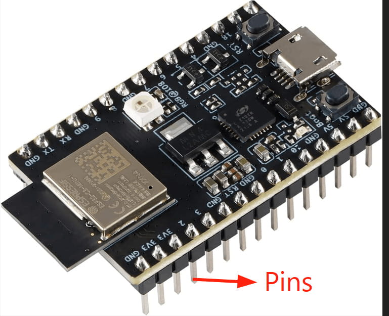
Pins
If you look at a microcontroller chip, you'll see metal legs sticking out of it. Those are called pins. Each pin is a physical point where the chip connects to the outside world (to buttons, LEDs, sensors, other chips, whatever your circuit has).
Each pin can do two things:
- Input: detect whether voltage is present on that pin or not. This is how the chip reads a button press or a sensor signal.
- Output: send voltage out through that pin or not. This is how the chip turns an LED on or off.
In both cases the chip is working with a simple binary signal, voltage present = 1, no voltage = 0.
Not all pins are the same.
Not every pin on a microcontroller does the same job. Different pins have different roles. Common types are:
- Power pins: one pin takes in the supply voltage (VCC) to power the chip, another connects to ground (GND) to complete the circuit. Every chip needs these.
- I/O pins: the pins you actually program and interact with. These are the ones you connect to LEDs, buttons, sensors etc.
- Reset pin: pulling this pin low restarts the chip, as if you cut and restored power.
- Programming pins: dedicated pins used specifically to upload code to the chip (UPDI on).
Most I/O pins are multi-functional.
A single physical pin can often have multiple purposes depending on how you configure it in the code. For example, one pin might be usable as a basic digital I/O pin, or as part of the UART serial communication peripheral, or as a PWM output, or as an analog input but only one at a time. You choose what role each pin plays when you write your program.
Ports
A port is just a group of those pins bundled together. Instead of the processor dealing with each pin individually, pins are organized into groups called ports, typically 8 pins per port on AVR chips. The processor controls an entire port through one register (a register I talked about earlier which is a storage location inside the chip). Writing a value to that register sets the state of all 8 pins at once.
ESP32
ESP32 Architecture and Processor Family
Architecture:The design or “blueprint” of a processor that explains how it works. It shows how the processor handles instructions, memory, and communication with other parts of the system.
Processor Family: A processor family is simply a group of processors that share the same core design and architecture but may differ in speed, number of cores, or features. For example, the Xtensa LX6 is the processor family used in the ESP32, while the RISC-V is the processor family used in the ESP32-C3.
The ESP32 is based on the Xtensa® LX6 architecture, designed by Cadence. It is a 32 bit dual core processor, meaning it can handle data in 32-bit chunks and run two tasks at the same time. Each core can run up to 240 MHz, making it fast enough for tasks like audio processing, wireless communication, and real time sensor reading.
The image below shows the ESP32 microcontroller's functional block diagram, taken directly from the official ESP32 datasheet.
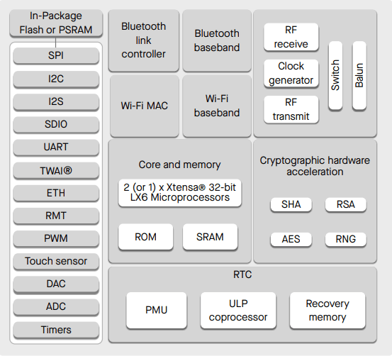
ESP32 Functional Block Diagram
- Processor (CPU): The main “brain” of the chip. It can run 1 or 2 cores at the same time to handle multiple tasks faster.
- ROM: Permanent memory that stores startup instructions for the chip. It cannot be changed.
- SRAM: Temporary working memory used while programs are running. It is cleared when power is off.
- Wi-Fi and Bluetooth: Built in wireless systems that let the ESP32 connect to networks and devices.
- Bluetooth System: Handles sending and receiving Bluetooth signals and managing connections like pairing.
- Wi-Fi System: Manages connection to wireless internet networks.
- RF System: The hardware that sends and receives radio signals through the antenna.
- Clock Generator: Keeps all parts of the chip working in sync with precise timing.
- Switch: Quickly changes the antenna between sending and receiving signals.
- Peripherals: Tools that let the chip connect to sensors and devices using different communication methods like SPI, I2C, UART, and more.
- Power System (RTC & PMU): Controls power use, keeps time during sleep mode, and helps the chip save energy in battery-powered projects.
Important Findings from the Datasheet
I used Claude AI to review the datasheet, asking it to summarize the key points and explain them in simple terms.
This was the prompt:
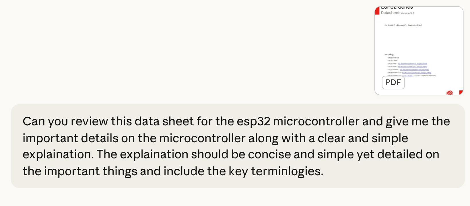
ESP32 Series: ESP32 Series Datasheet v5.2
- Chip (ESP32-D0WD V3): A dual core chip used for Wi-Fi and Bluetooth projects with low power use.
- Speed (80 to 240 MHz): The processor speed can change to save power or increase performance.
- Wireless: Built in Wi-Fi and Bluetooth so no extra modules are needed.
- Signal Strength: Can send strong Wi-Fi signals for stable long distance connections.
- Memory: Has storage for system files and working memory for running programs.
- Pins: Many input/output pins and supports sensors, motors, and communication tools.
- Low Power: Uses very little energy in sleep mode, good for batteries.
- Power: Runs on 3.3V, which is standard for microcontrollers.
- Security: Has built-in protection to keep data safe and encrypted.
- System: Uses FreeRTOS to manage tasks efficiently in the background.
- Programming: Works with Arduino, MicroPython, ESP-IDF, and other tools.
XIAO ESP32 C3
The image below shows the ESP32 C3 microcontroller's functional block diagram:
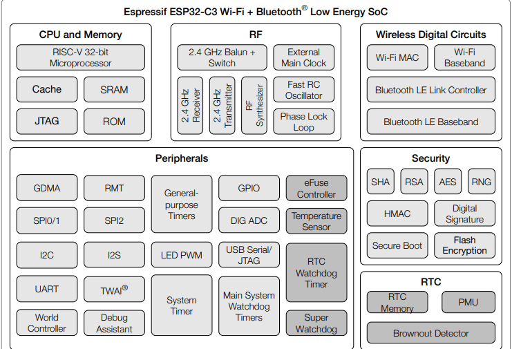
The ESP32 C3 has a fast 32 bit RISC V processor with memory (SRAM, ROM, and cache) to help it run smoothly. It also has built-in wireless support for 2.4 GHz Wi-Fi and Bluetooth Low Energy. The board includes many useful pins and communication options like GPIO, SPI, I2C, UART, ADC, PWM, and timers for connecting and controlling devices. It also has strong security features such as encryption and secure boot to protect data. Finally, its power system helps manage energy use and can reset the chip if the voltage becomes too low to keep it working safely.
Important Findings from the Datasheet:
XIAO ESP32C3 Seeed Studio XIAO ESP32C3 Datasheet
- Chip (ESP32 C3): A small and efficient processor that runs the board.
- Speed (160 MHz): Controls how fast it processes tasks and instructions.
- Wireless: Has built in Wi-Fi and Bluetooth for connecting to devices.
- Pins: Includes digital and analog pins to connect sensors and parts.
- Low Power: Uses very little energy in sleep mode, good for batteries.
- Battery Charging: Can directly charge a connected battery.
- Power: Runs on 3.3V, which is low power and safe for electronics.
- Programming: Works with Arduino, MicroPython, and other tools.
- System: Uses FreeRTOS to manage tasks efficiently.
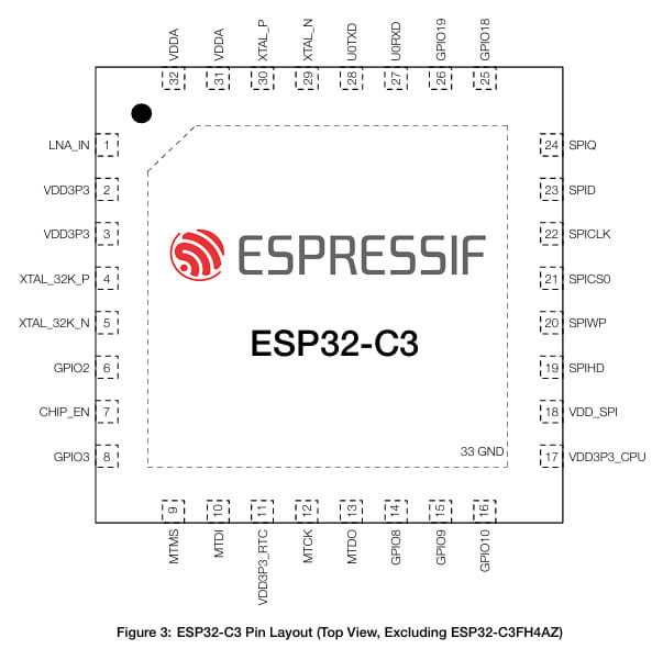
This is the pin layout, it is a top down view of the bare ESP32-C3 chip showing all 33 pins around its edges:
Programming a microcontroller
I will be using Wokwi to program an Arduino for this project. I chose it because it is free, browser-based, requires no installation, and allows me to build and test circuits virtually without needing any physical hardware.
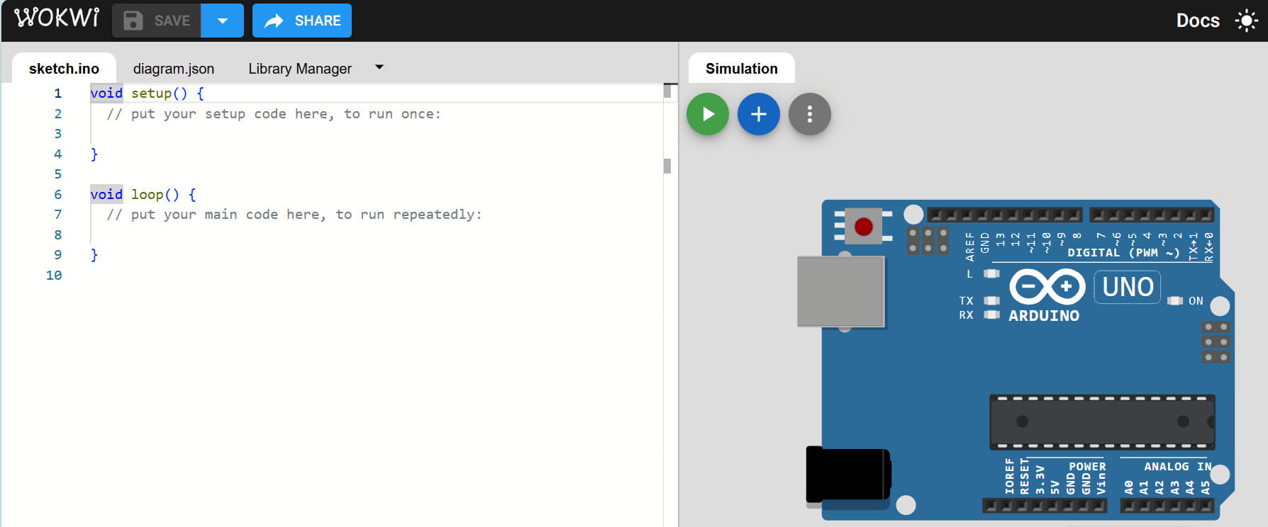
First, I went to the software's official website and started a new project by selecting Arduino Uno under 'Start from Scratch'.
.jpg)
This opened a blank workspace set up specifically for the Arduino Uno, showing all its pins and default settings.
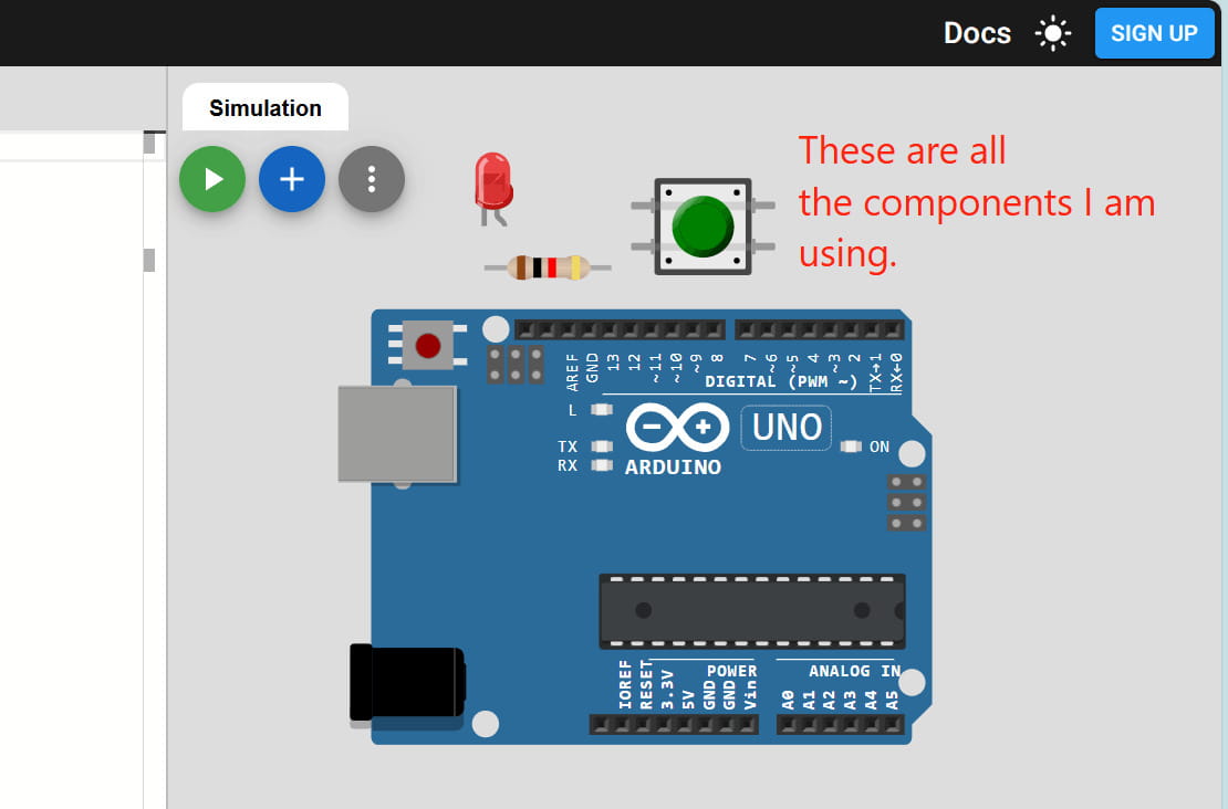
I could now begin adding components to the circuit. I decided to create a basic Arduino circuit with an LED and a push button.
 (1).jpg)
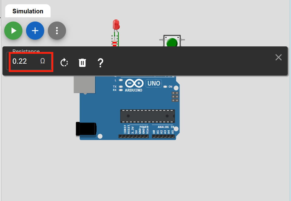
First, I started by setting up the LED. I connected the shorter leg (the cathode) directly to one of the GND pins on the Arduino. Then, I took a resistor and set it to 0.22 K ohms and connected it from the longer leg of the LED to Digital Pin 13.
.jpg)
Next, I moved on to the push button. I placed it on the breadboard and connected one of its legs to Digital Pin 2. For the other side of the button, I ran a wire straight to a GND pin.
.jpg)
And that was it, the hardware part was done. Then for the code, I asked gemini to generate a code to make the LED blink and wait for one second before turning off when the button was pressed. And I prompted gemini to give explanations for the code as well.
This was the prompt I used:
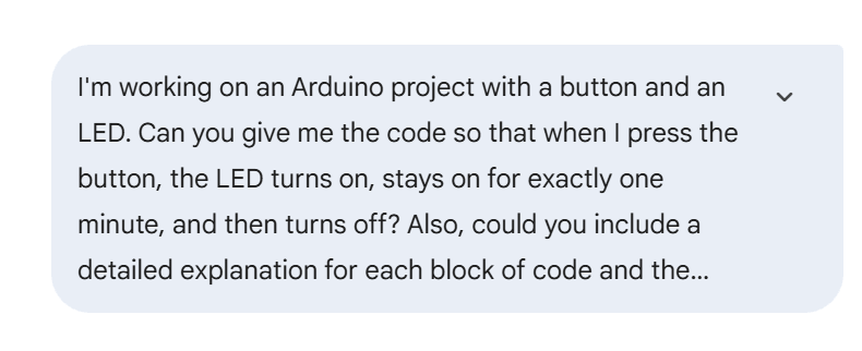
This was the code it generated:
/* --- VARIABLE DEFINITION BLOCK ---
   This section gives names to the physical pins so we don't
   have to remember numbers throughout the code. */
const int ledPin = 13;    // Set 'ledPin' to pin 13 (where the LED is connected)
const int buttonPin = 2;  // Set 'buttonPin' to pin 2 (where the button is connected)


/* --- SETUP BLOCK ---
   This runs exactly ONCE when the Arduino powers on or is reset.
   It configures the pins for their specific jobs. */
void setup() {
  // Configures pin 13 to send power OUT to the LED
  pinMode(ledPin, OUTPUT);

  // Configures pin 2 to listen for signals.
  // INPUT_PULLUP activates an internal resistor that holds the pin
  // at HIGH (5V) until the button connects it to Ground.
  pinMode(buttonPin, INPUT_PULLUP);
}


/* --- MAIN LOOP BLOCK ---
   This block runs over and over again (thousands of times per second)
   as long as the Arduino has power. */
void loop() {
  // digitalRead checks if Pin 2 is currently HIGH or LOW.
  // We store that "state" in a temporary variable called 'buttonState'.
  int buttonState = digitalRead(buttonPin);


  /* --- LOGIC BLOCK: CHECK FOR PRESS ---
     Because we used INPUT_PULLUP, a "LOW" reading means the button
     is physically completing the circuit to Ground. */
  if (buttonState == LOW) {

    // Step 1: Send 5V to Pin 13 to light the LED
    digitalWrite(ledPin, HIGH);

    // Step 2: Pause the entire program for 1000 milliseconds (1 second)
    // The LED stays ON during this pause.
    delay(1000);

    // Step 3: Stop sending power to Pin 13 to turn the LED OFF
    digitalWrite(ledPin, LOW);

    /* --- HOLDING BLOCK ---
        This 'while' loop tells the Arduino: "Do nothing as long as the
        button is still being held down." This prevents the LED from
        blinking again until you let go and press it a second time. */
    while (digitalRead(buttonPin) == LOW) {
      delay(10); // A tiny 10ms delay to keep the processor stable
    }
  }
}
Explanation for the code:
The code is divided into 4 main parts to make it easier to understand and organize.
1. Variable Definition Block
Gives names to the pin numbers
ledPin = pin 13 (controls the LED)
buttonPin = pin 2 (reads the button)
Makes the code easier to read and change
2. Setup Block (runs once)
Runs only when the Arduino starts
Sets up the pins:
LED pin is set as OUTPUT (it can send power to the LED)
Button pin is set as INPUT_PULLUP
INPUT_PULLUP means the button normally reads HIGH until pressed
3. Main Loop Block (runs forever)
Keeps checking if the button is pressed
Because of INPUT_PULLUP:
LOW = button is pressed
When pressed:
LED turns ON for 1 second
Then turns OFF
4. Holding Block
Stops the loop from repeating too fast while the button is held
Uses a while loop to wait
LED won't blink repeatedly until the button is released and pressed again
This is the results:

The LED lit up when I pressed the button.
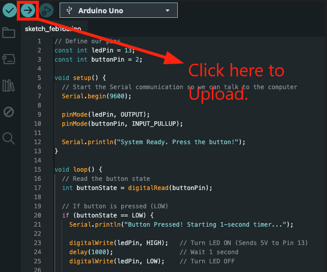
After building and testing the circuit in simulation, I decided to recreate it using real hardware. I opened the Arduino IDE and pasted the same code I had used in my simulation.
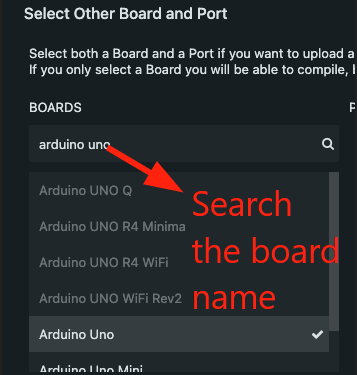
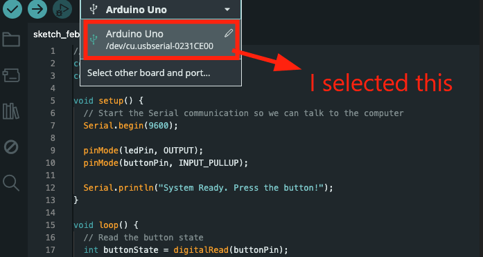
After that, I selected the correct board from the board menu. For my hardware setup, I used the Arduino Metro board, so I made sure it was chosen before uploading the program. While selecting the board in Arduino IDE, I chose Arduino Uno. After connecting my Metro board via USB, the device name appeared in the list, confirming that the board was successfully detected. Then, I uploaded everything by clicking on the arrow button.
Then, I pressed the push button to check if everything was working. It did! The LED turned on, stayed lit for a second, and then turned off.
Yay to my first circuit!╰(*°▽°*)╯
Project Development
For this week's project development, I wanted to apply what I learned this week to my final project. To do this, I created a simple demonstration of the menu structure I designed earlier. I started by building a basic simulation in Wokwi based on the draft menu layout I made last week.
 (1).jpg)
In Wokwi, I set up the required components, including an ESP32 C3 microcontroller, LEDs, resistors, a breadboard, and an OLED display. The simulation is simple and cycles through the different menu screens to give a rough idea of how the user interface might look. This version is mainly for visualization, and I plan to improve it later with proper input handling and navigation logic.
This is the first simulation I made, which only had a few components:
This is the second video, which has more components, and I updated the code to cycle through different menu structure for the demonstration:
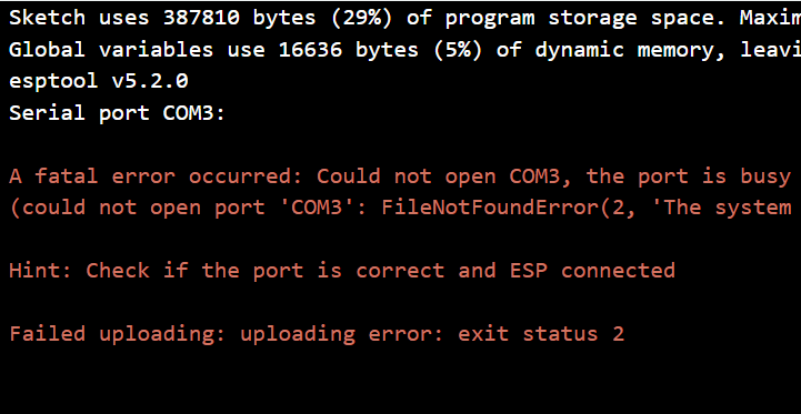
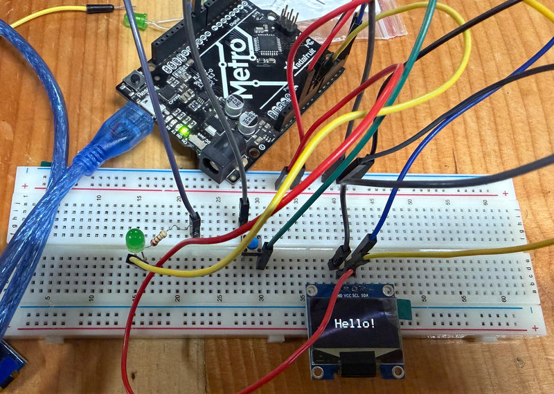
After completing the simulation, I attempted to recreate the same setup using real hardware. I initially used a bare Seeed Studio XIAO ESP32 C3 mounted on a breadboard, since there wasn't enough time to design and fabricate a custom board. I wired the circuit to match the simulation, but it did not work as expected since the oled was not displaying anyhting. It was because the microcontroller was not successfully driving the output pin. After checking the wiring, I found that all connections matched the simulated circuit, but the issue may have been related to incorrect pin mapping on the physical board compared to the simulation and I was haing trouble with the port connection with the microcontroller. So for demonstration purposes, I then switched to an Arduino Metro board, which allowed me to continue testing and showcasing the concept.
To indicate when the system is active, I added an LED to the circuit and followed these steps:
- Step 1: Connected the short leg (cathode) of the LED to the GND pin.
- Step 2: Connected the long leg (anode) to a 220 ohm resistor.
- Step 3: Connected the other end of the resistor to Digital Pin 3 on the Metro board.
- Step 4: Connected the push button to Digital Pin 2 and GND.
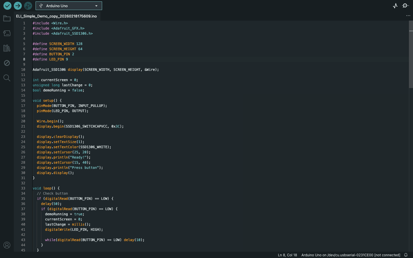
I had a very hard time programming the oled display. It remained stuck on "Hello" instead of cycling through different menu structure. It turns out, the code was too long for the oled display, so I used Claude AI to shorten the initial code and it worked!
Here is the video:
_result.jpg)
Reflection:
This week introduced a lot of new concepts and terminology, and it was overwhelming at first, but I gradually got a basic understanding of the most important terms.It was really cool to be able to make circuits by myself!