Week 3: Computer Controlled Cutting
Assignments:
Group assignment:
- Characterize your lasercutter's focus, power, speed, rate, kerf, joint clearance and types.
- Document your work to the group work page and reflect on your individual page what you learned.
Individual assignment:
- Design, lasercut, and document a parametric construction kit, accounting for the lasercutter kerf, which can be assembled in multiple ways.
- Cut something on the vinyl cutter.
Learning Outcome:
- Demonstrate and clearly explain parametric 2D modeling workflows.
- Identify and describe the key processes involved in operating a laser cutter.
- Design, develop, evaluate, and fabricate a parametric construction kit.
- Identify and explain the essential processes involved in using a vinyl cutter.
This is the timetable for this week to help me keep things in track:
 (1).jpg)
Group Assignment:
For this week, we had to do our first ever group assignment along with our individual assignment. For the group assignment, we had to characterize our lasercutter's focus, power, speed, rate, kerf, joint clearance and types and then we had to document our work on the group work page and reflect on our own individual page about what we learned. For the group documentation, we agreed to take turns to document when we have group assignments. You can access our group assignment here.
Before carrying on with our group assignments, our local instructor walked us through the basic steps on how to use the laser cutter and how it works as well and explained a few keywords to us, so that we can understand the group assignment.
An overview of things I've learned:
Computer-controlled machines are automated devices that execute precise operations based on digital instructions. Common examples include 3D printers, CNC routers, and laser cutters. A laser cutter is a computer-controlled machine that uses a focused, high-power laser beam to cut, engrave, or etch materials with high precision.
This is the labeled image of the laser cutter in our lab:
.png)
Setting up the Laser Cutter:
- Flip the main switch on the laser cutter to initialize the internal computer and motors.
- Turn on the Exhaustor. This is non-negotiable since it creates a vacuum that pulls hazardous smoke and vaporized material out of the machine.
- Turn on the air compressor. This powers the Air Assist, which blows a constant stream of air at the Focus Point. This prevents the material from catching fire and protects the expensive laser lens from soot.
- Use a Caliper which is a precision measuring tool to measure the exact thickness of your material. Place your material on the honeycomb bed, ensuring it lies perfectly flat.
Engraving
Engraving is the process of etching a surface. It's like the laser acting like a printer head moving rapidly back and forth.
- In inkscape or any other design tool, open your file. Select your image and go to Path > Trace Bitmap to convert your design into a Vector.
- For engraving, set the Fill to solid black, Stroke to 'None' and put stroke style as 0.05mm. This tells the laser to treat the shape as a solid object to be filled with heat.
- Press Ctrl + P to access the settings, then select Print to open the Epilog dashboard.
- Once it's open, adjust the speed and power based on the type of cut you want. Lower power results in a lighter cut, while reducing the speed produces a darker, deeper cut.
- Move the pink preview frame on your screen to place your design exactly where your material is located on the bed.
- Press the "Print" icon on the dashboard to send the job to the machine.
Vector Cutting
Vector cutting is when the laser follows a continuous path to cut all the way through the material.
One important thing to understand here is the key terminology called Kerf. Kerf is the small amount of material that gets cut away by the tool like the laser, making the cut slightly wider than the design line. It's important to know the kerf of your laser because when a laser cuts, it burns away a thin line of material (the kerf). This makes holes slightly bigger and pieces slightly smaller than the original design, so knowing the kerf helps you adjust dimensions to get accurate fits. It's also important to to note that Kerf changes with material type, thickness, and the laser settings.
- In Inkscape, select the path you want to cut.
- Set the Fill to "None." Set the Stroke Width to exactly 0.025 mm or hairline. Note: Avoid overlapping lines! If two lines are on top of each other, the laser will cut the same spot twice. This increases the Kerf, making the cut look charred, and inaccurate.
- Go to the Epilog Dashboard. Ensure Engrave is toggled OFF and Vector is toggled ON.
- Change the speed and power depending on how you want the cut.
- On the Epilog Fusion, use the joystick to move the lens over your material. Select the Auto Focus option. The machine will automatically move the bed so the material is at the perfect Focus Point.
- Select your file on the machine's screen and press the main start button.
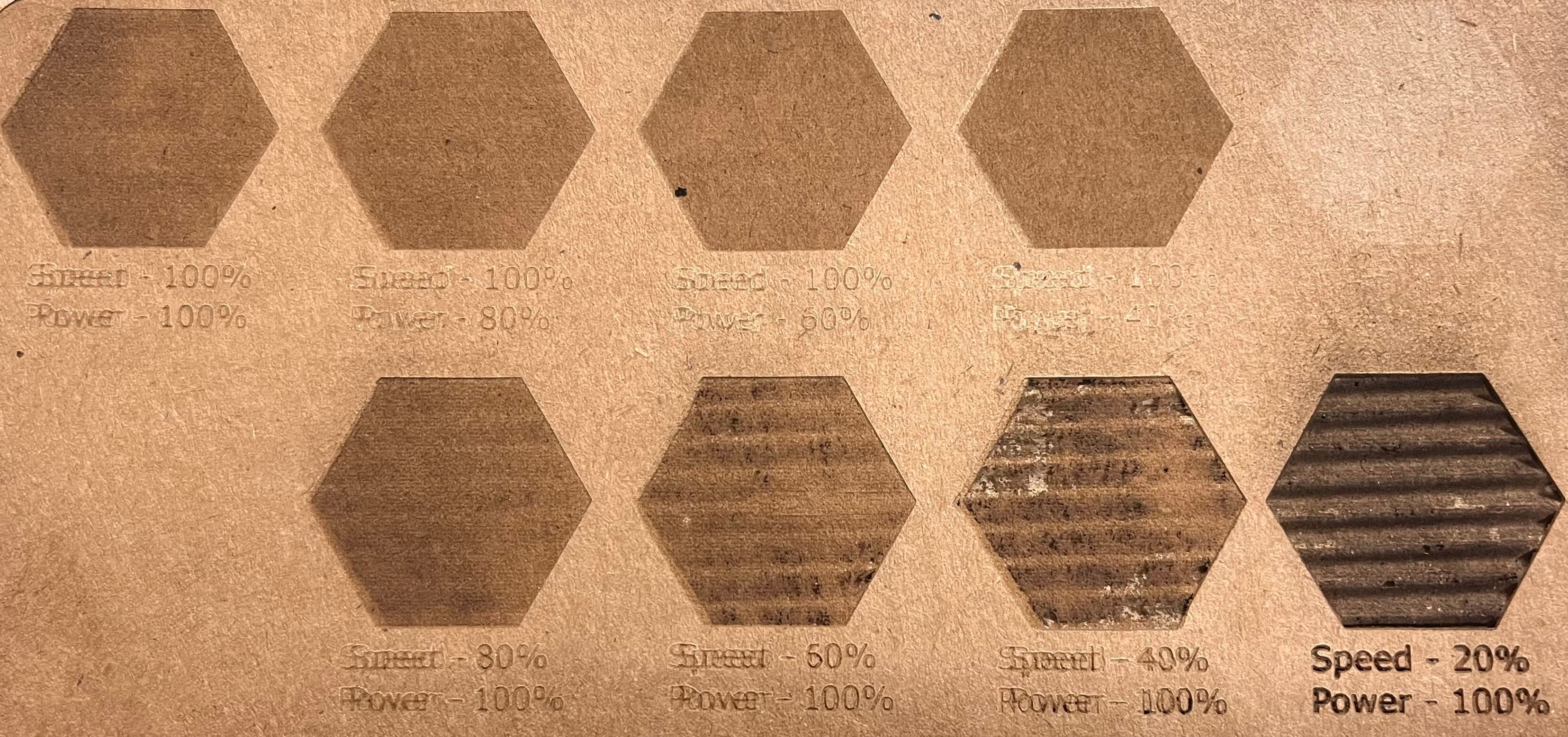
Next, we began testing how the "speed" and "power" settings affected the engraving.
Next, we started to find out the kerf of our laser cutter.
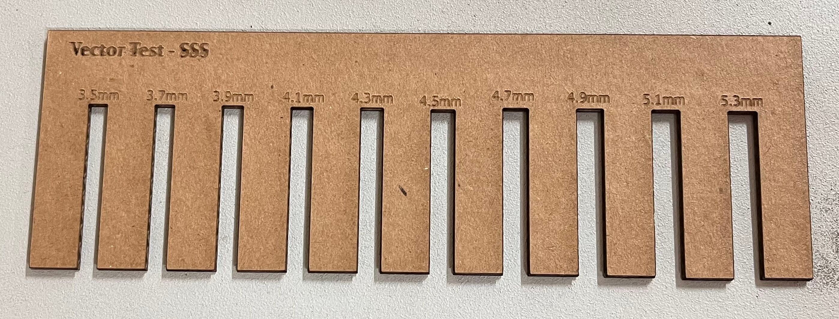
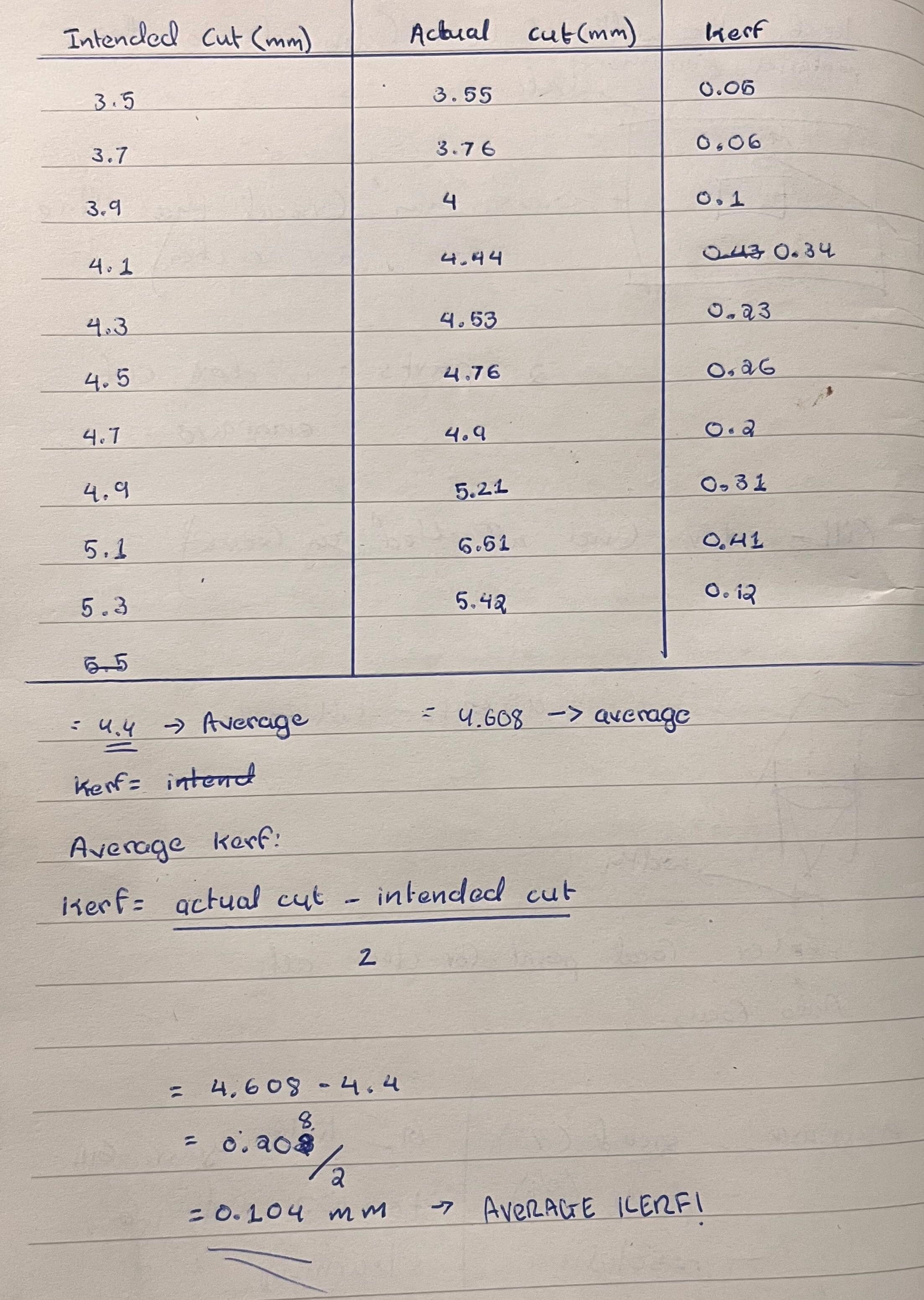
We measured the actual width of the cut using a caliper to get a precise value for our slot. Then, we used this measurement in this formula to calculate the kerf.
Formula: kerf = (actual cut - intended cut) / 2
Safety Protocols for Laser Cutter Operation
These are some of the important safety protocols for laser cutting, compiled from a resource by the University of Wisconsin Madison.
Hazards:
Fire and Thermal Risks
- The laser cutting process involves burning away material, which generates intense heat and poses a fire risk.
- Certain materials may ignite during cutting, especially if settings are too aggressive or if debris accumulates.
- Dust and residue buildup inside the machine can become fuel for fires.
Toxic Fumes and Air Quality
- Cutting plastics and certain materials releases Laser Generated Air Contaminants (LGACs), including hazardous substances like benzene, hydrochloric acid, and isocyanates.
- These fumes are harmful if inhaled and require proper ventilation.
- Exhaust systems must be properly installed according to manufacturer specifications and vented directly outside the building.
Additional Physical Hazards:
- Direct or reflected laser beam exposure can cause permanent eye injury or skin burns.
- Cut materials often have sharp edges that can cause cuts or puncture wounds.
Safety Rules
Operator Responsibility:
- NEVER LEAVE THE MACHINE UNATTENDED. A live laser is an active ignition source. You must maintain direct visual observation throughout the entire job.
- Always have a properly maintained fire extinguisher readily accessible.
- Maintain a clean, clear workspace. Remove all scraps, papers, solvents, and other combustible materials from the area around the machine before operation.
- The exhaust system must be operational before and during all cutting or engraving jobs. Proper ventilation removes hazardous fumes from the workspace.
Machine Maintenance
- Regularly clean the interior of the laser cutter, removing debris between uses.
- Never modify or disable any safety features, covers, or interlocks.
- Do not operate if the viewport is damaged, doors are removed, or safety systems are compromised.
- The door safety interlock automatically shuts off the laser when the lid is opened. This critical safety feature must never be bypassed or disabled.
- Do not remove protective covers or access internal components. Only authorized technicians should perform internal maintenance.
Personal Protection
- Never look directly into the laser beam or use optical instruments to view it.
- Only using approved materials, many common plastics produce toxic fumes when laser cut.
- Always verify that the exhaust system is functioning before starting any job.
Individual Assignment:
For the individual assignment, we are required to design, laser cut, and document a parametric construction kit that accounts for the laser cutter's kerf. The kit should be able to be assembled in multiple ways, and we are required to create a design to cut on the vinyl cutter as well.
Parametric Designs
Parametric design is a digital design method where elements of a model like dimensions, angles, or shapes are defined by adjustable parameters or variables rather than fixed numbers. Changing a single parameter automatically updates the entire design based on predefined relationships and rules. Using parametric designs, we are asked to design and laser cut a press fit construction kits. A press fit construction kit is a set of modular pieces that connect by friction, without using screws, or other tools.
I made my design using Fusion 360. To begin, I went to the Modify menu on the top toolbar and selected Change Parameters from the dropdown. This opened the Parameters dialog box, where I could define and manage all the key values used in my design, such as material thickness, slot width, and kerf allowance.
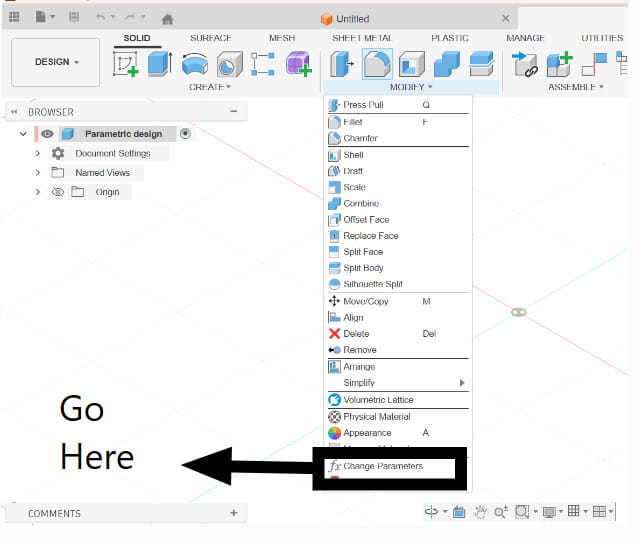
I created five different parameters to make my design fully parametric and easy to adjust.
.jpg)
The kerf value used in the Fusion 360 parameter table was taken from the measurements obtained during the group assignment. We measured the kerf by cutting test pieces and comparing the designed dimensions with the actual dimensions after cutting. The measured kerf value was then used in my design parameters for the press-fit parts.
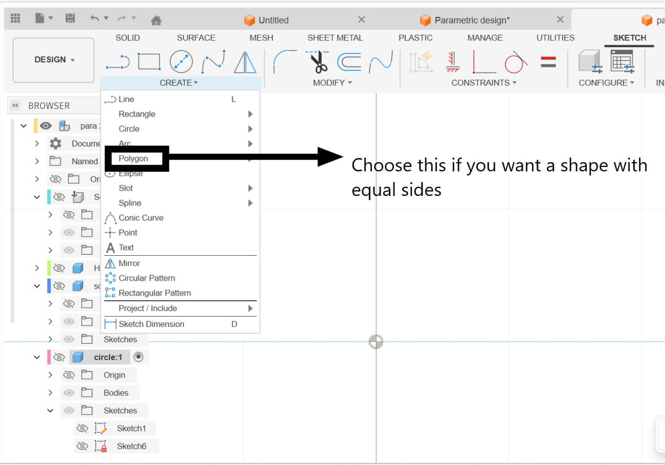
Then, I created a new sketch by going to Create > Create Sketch and selected the plane I wanted to work on. From the Create dropdown, I chose Polygon to make the first piece of my design, which was a triangle. I set the number of sides to 3 and placed the shape on the sketch.
 (1).jpg)
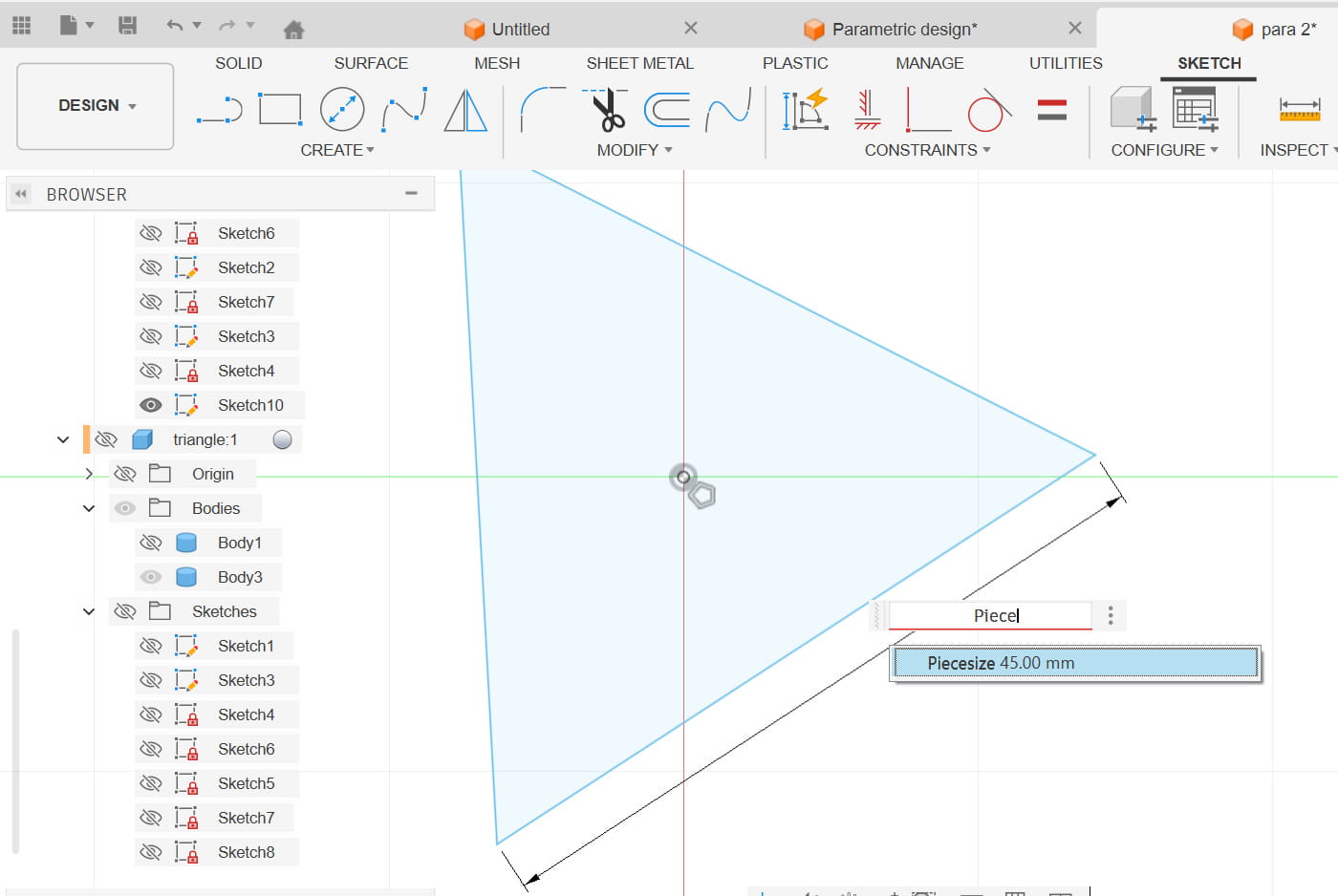
After that, I added the required dimensions by typing in the parameter names instead of fixed values. This allowed the triangle to automatically update whenever I changed the parameters.
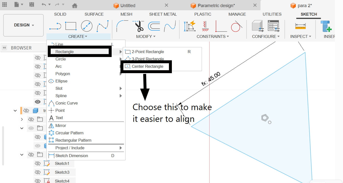
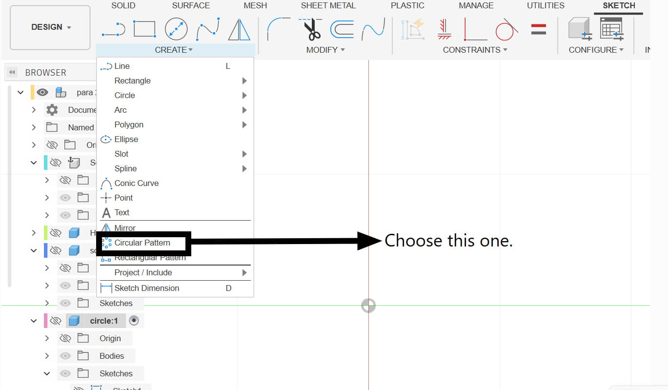
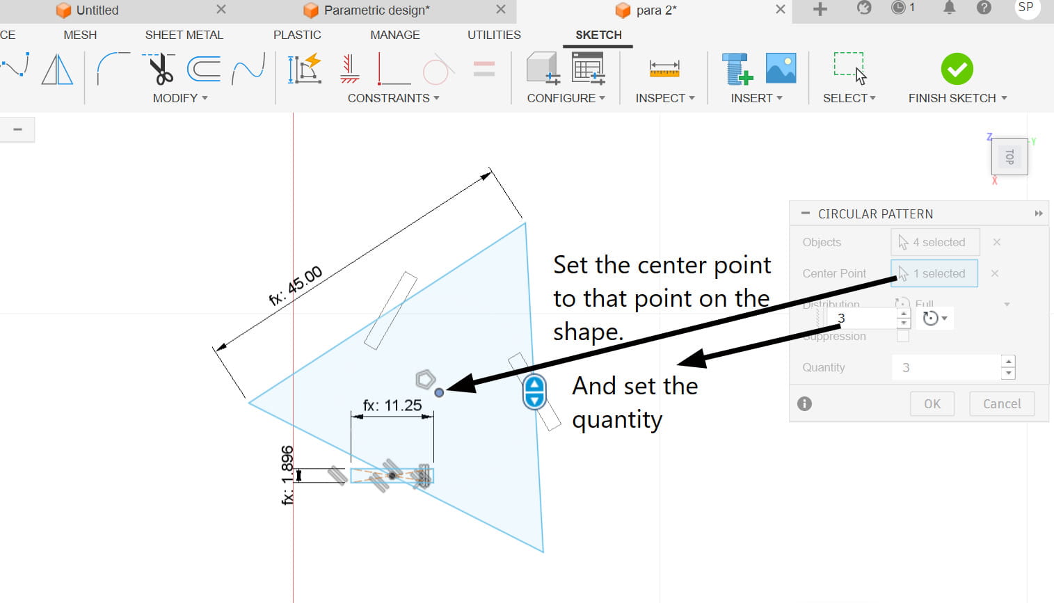
Next, I created the slots on each side by sketching a rectangle for one slot. Once the first slot was properly positioned and dimensioned using parameters, I used the Circular Pattern tool to duplicate the rectangle evenly around the shape. This ensured that each side had identical slots placed at equal angles, keeping the design symmetrical.
 (1).jpg)
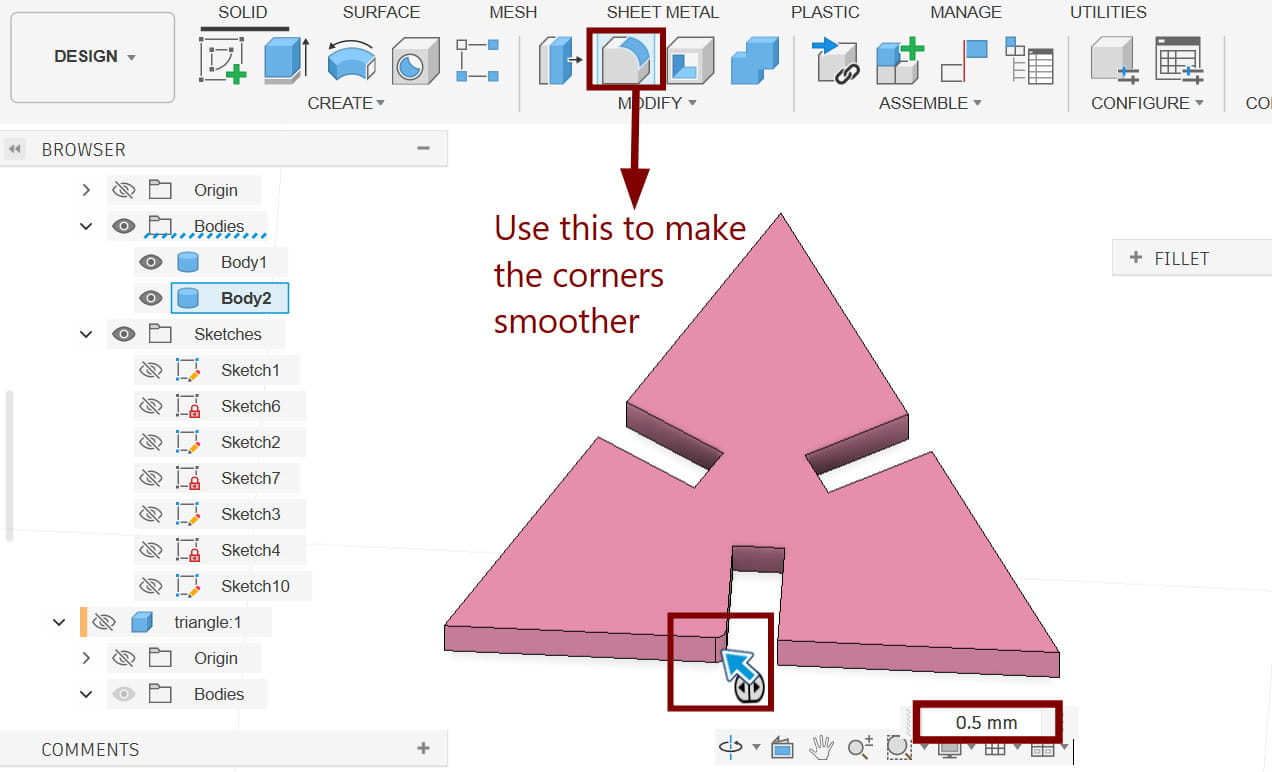
After aligning everything correctly, I extruded the sketch to the required thickness of 2 mm. Once the extrusion was done, I used the Chamfer tool on the sharp corners of the slots to slightly round them off. This helps the pieces slide into each other more smoothly during assembly.
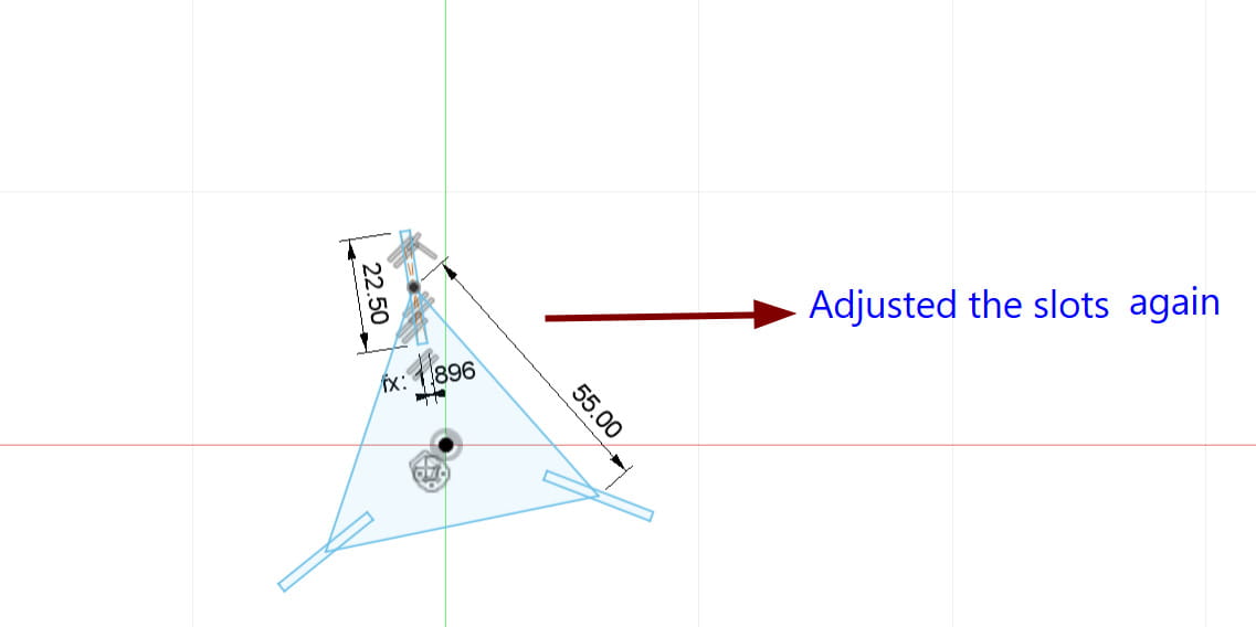
After some time, I realized that the slots were not positioned correctly, so I went back and adjusted their placement to ensure they aligned properly with the design.
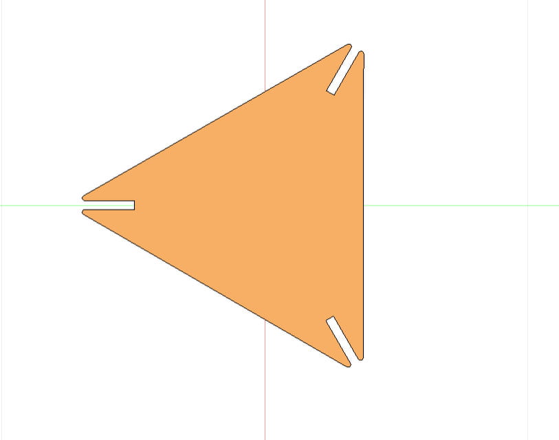
Yay! The first piece of our parametric design is finally complete.
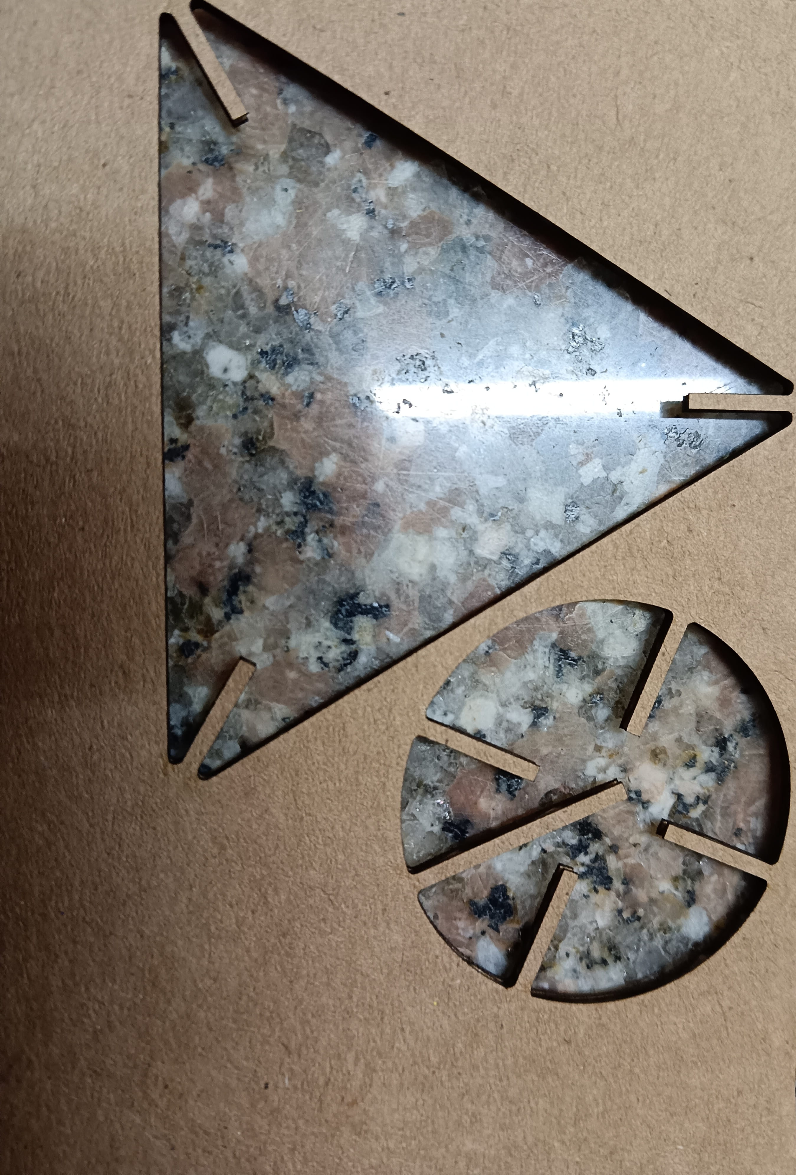
Next, I moved on to creating my final piece, which was a circle. I followed the same steps as before, but instead of using a polygon, I created a center point circle. I set the radius to be half of the actual size of the piece.
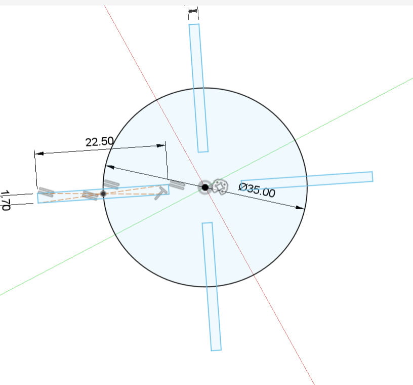
Then, in the center of the circle, I added an extra slot that was longer than the others. This slot allows me to connect pieces vertically, making it possible to assemble a 3D object by fitting other pieces into the slot from below.
This is the final piece:
.jpg)
Laser cutting the parametric design
After finishing my design in Fusion 360, I prepared it for laser cutting by saving it as a DXF file. I used the Project tool (Press P) to select the two pieces I wanted, which created a new sketch with purple edges and vertices. Then, I right-clicked the sketch and chose Export as DXF, saving it to my computer.
.png)
Next, I opened Inkscape and imported the DXF file. I duplicated the pieces and arranged them on the workspace to prepare them for laser cutting. I also changed the stroke style to 'Hairline', which is required for vector cutting so the laser follows the lines accurately.
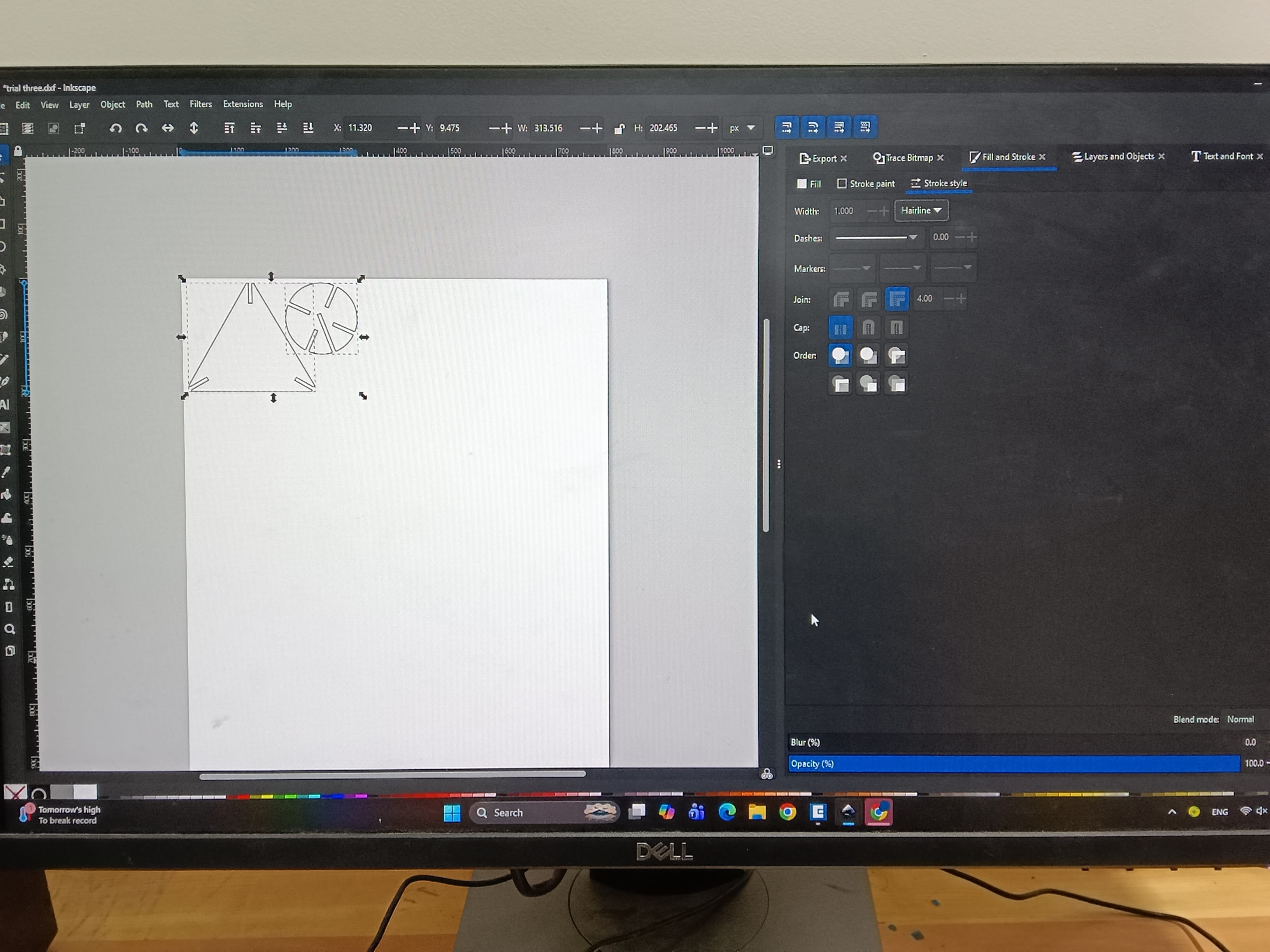
Then I pressed P to open the Epilog dashboard and modified the setting for vector cutting.
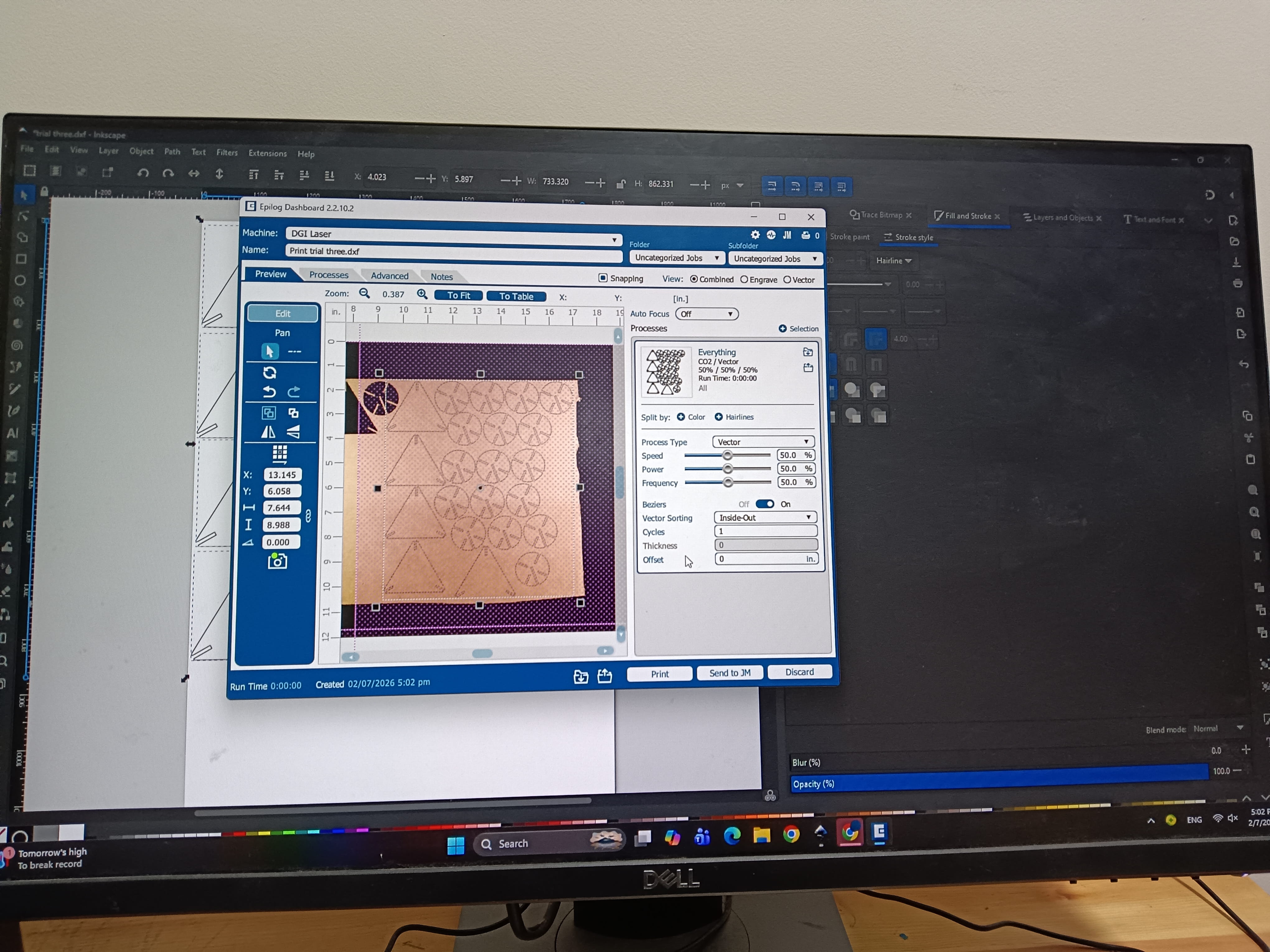
Trial 1
These are the results from my first cut. The pieces were a bit loose and didn't fit perfectly, so I went back to Fusion to adjust the design. It seems like more material was removed during cutting than expected because I did not fully account the actual material thickness and kerf precisly,creating extra clearance between the parts.
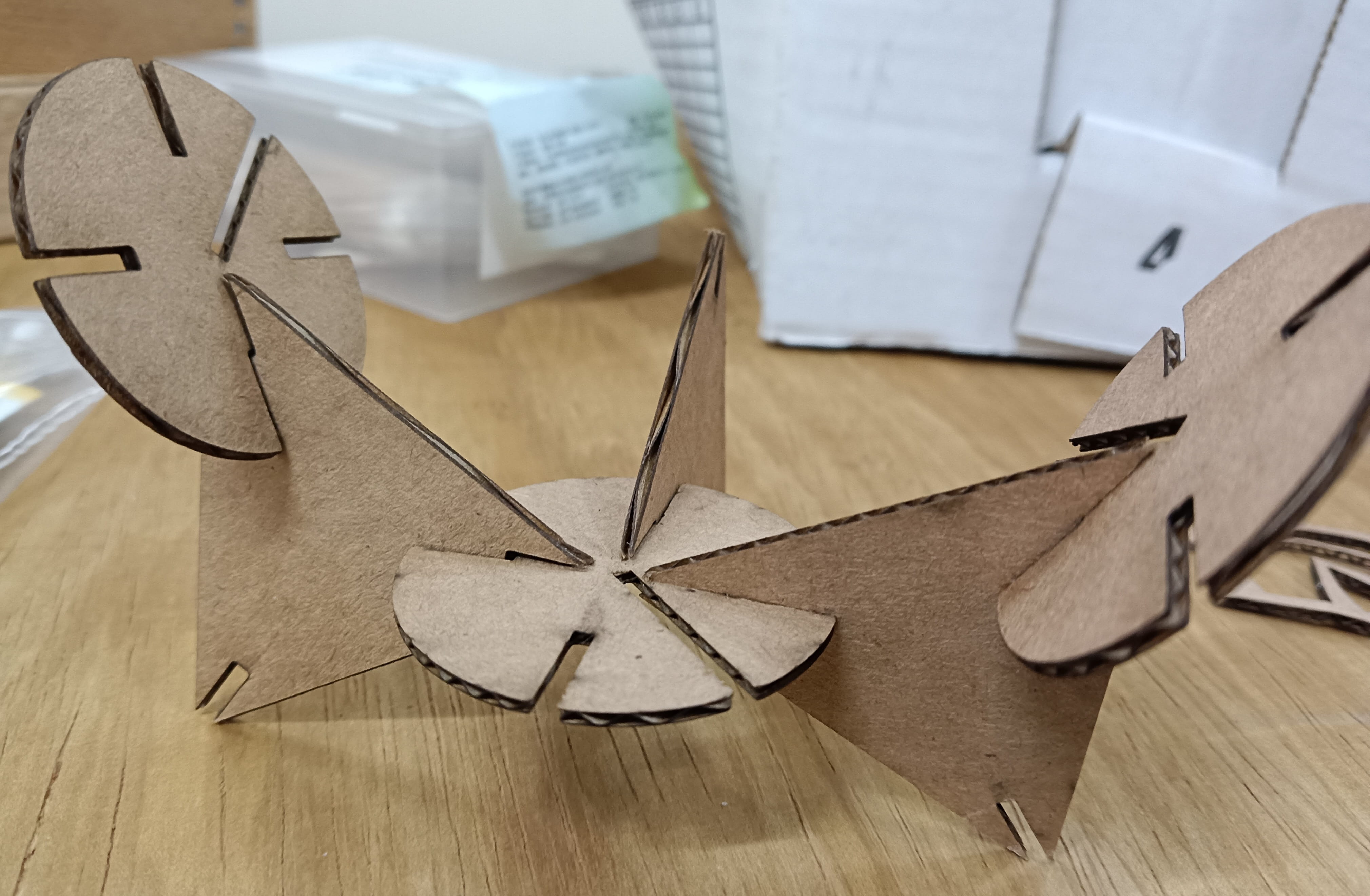
Trial 2:
After modifying the slot width, I tried cutting the pieces again and it worked out fine this time. Since the test worked out okay, I proceeded to laser cut the full set of pieces needed for my design.
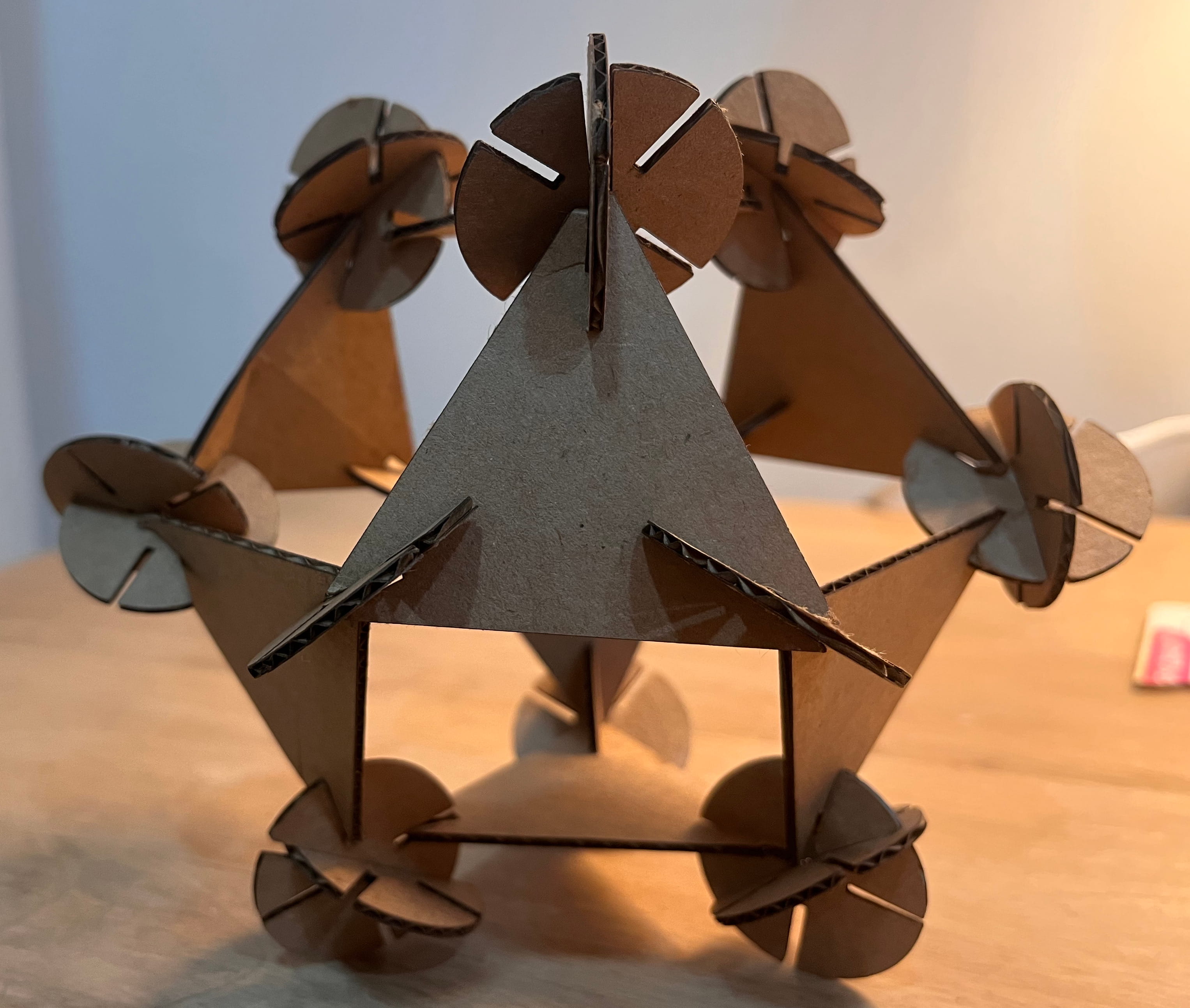
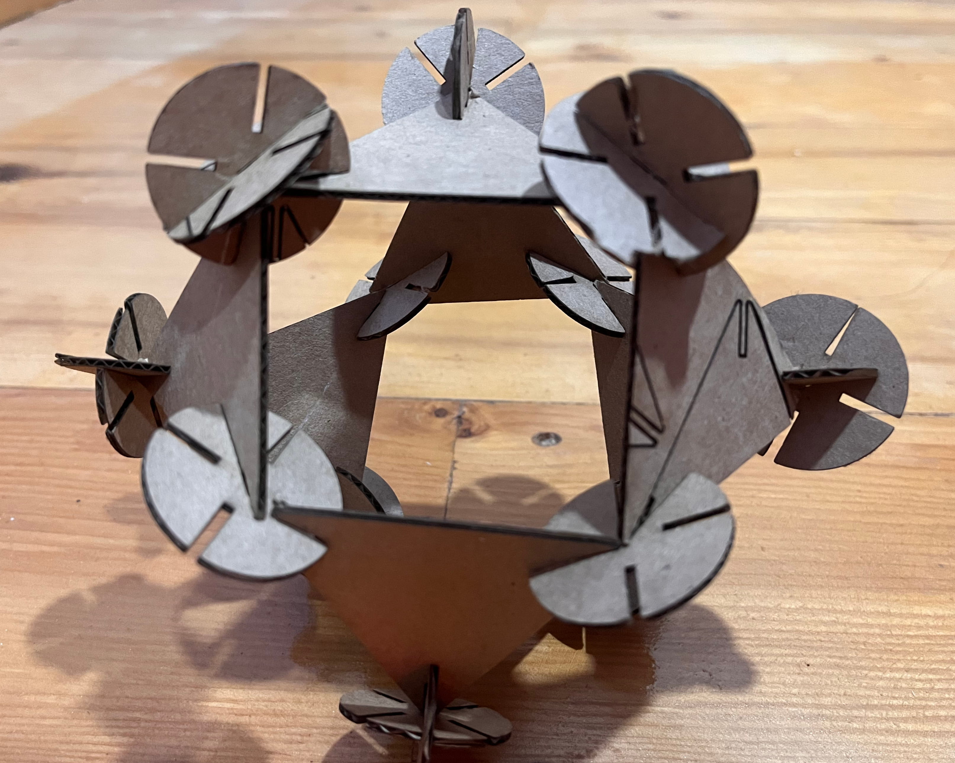
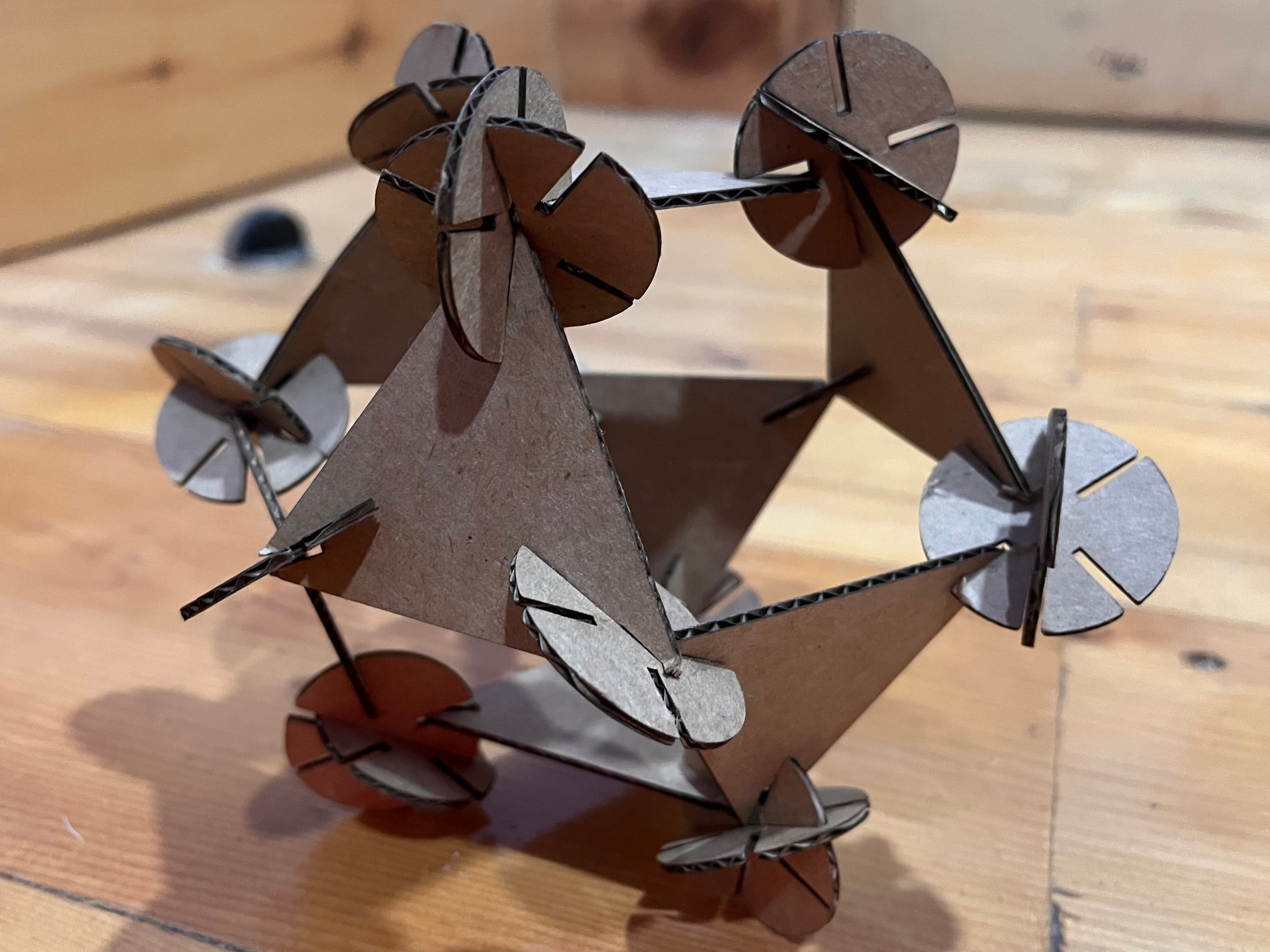
Then, I assembled all the pieces together. It took some time to get the shape just right. I got the design idea and a lot of guidance from Mr. Paul Nichols's Week 3 assignment page, a big thanks to him!
This is the final look (It's supposed to look like a Cuboctahedron.)
.png)
Vinyl Cutting Machine:
This week, we also got to use the vinyl cutting machine to create something of our own choice. A vinyl cutter is a computer-controlled machine that uses a small blade to accurately cut designs, letters, and shapes from thin, adhesive vinyl sheets.
The vinyl cutting machine in our lab is the Roland CAMM-1 GS-24.
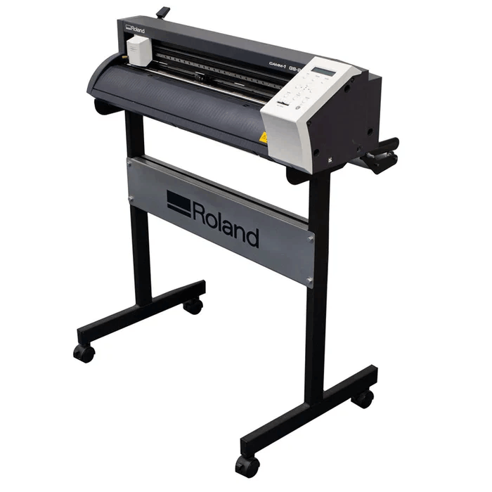
This image here shows the labeled parts of a vinyl cutter:
.png)
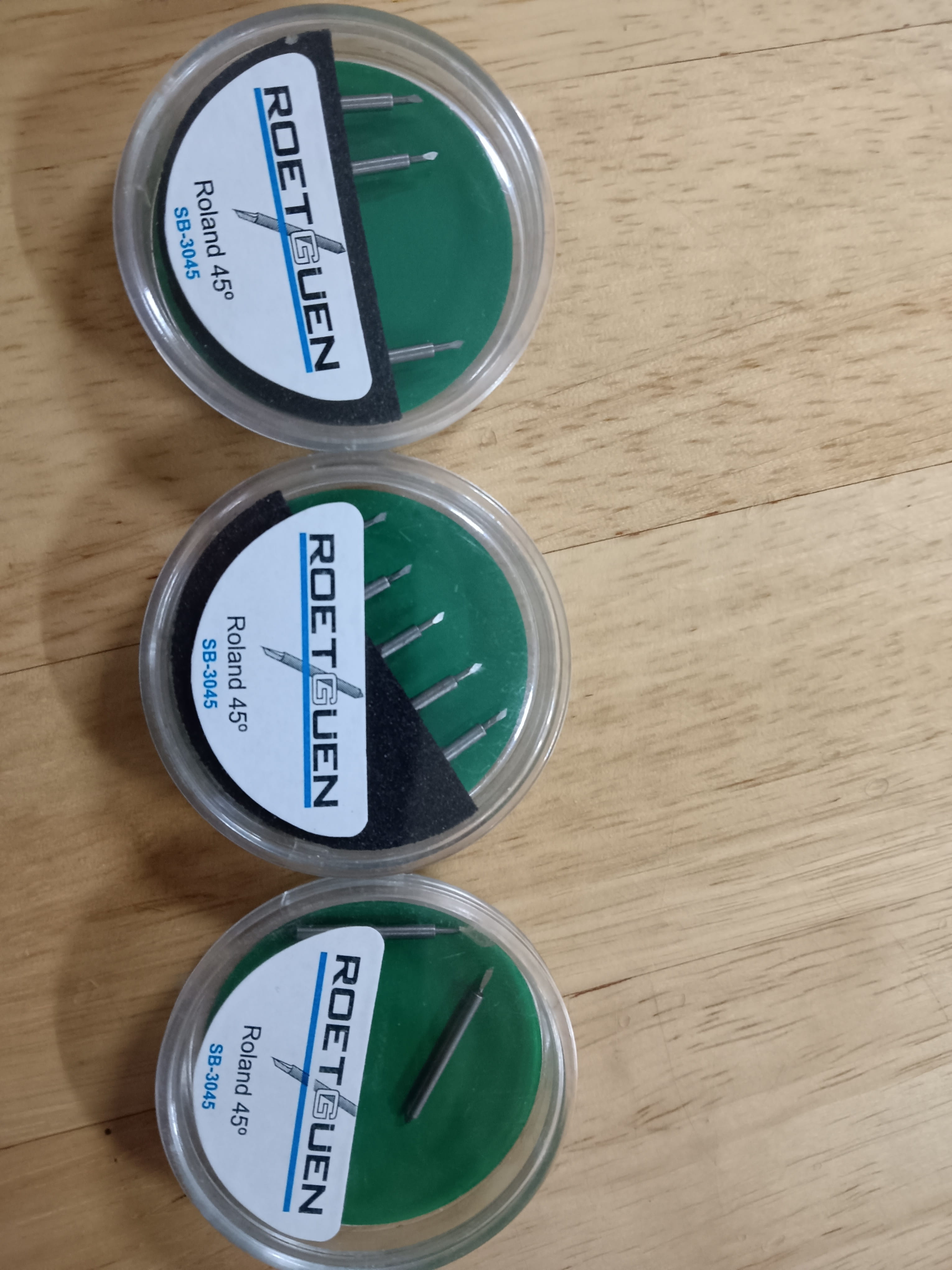
Our Roland CAMM-1 GS-24 vinyl cutter uses the Roetguen Roland 45° blade which is designed to be compatible with Roland vinyl cutters.
I decided to use the vinyl cutting machine to make custom stickers for my laptop. I downloaded a few sticker designs that I liked from Pinterest and used those for my cuts.
- I imported the downloaded images into the app called CutStudio using the import tool in the File tab.
.png)
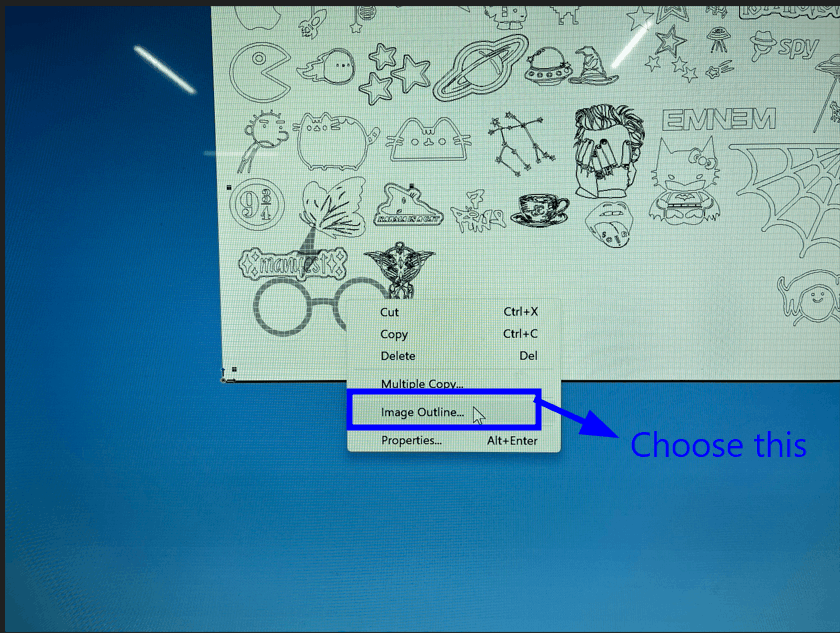
- To begin editing, right-click the image and select Image Outline.
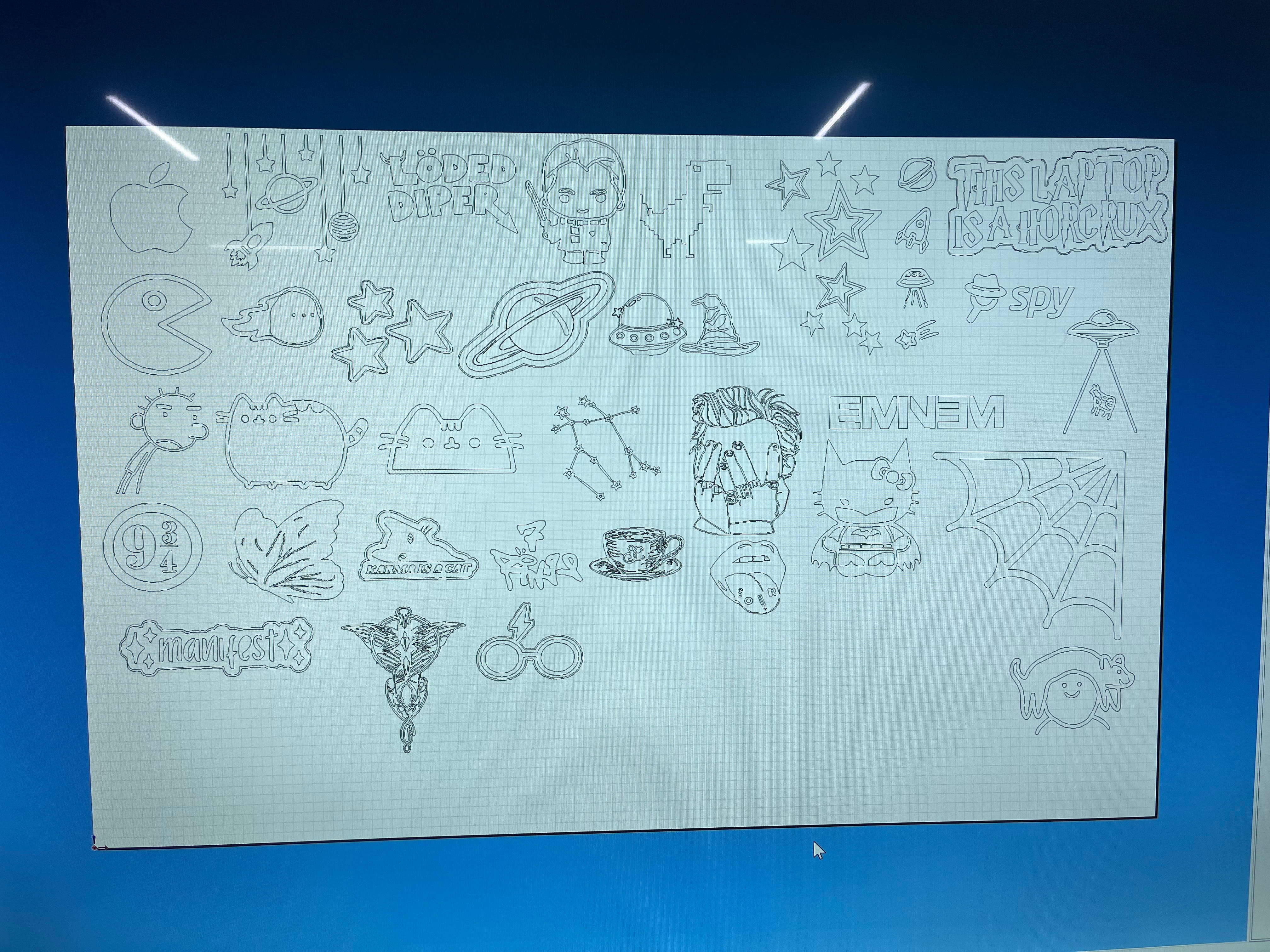
- Select Extract Contour Lines.
After repeating this process, this was me and azhim Sonam Pema's sticker collection ☆*: .。. o(≧▽≦)o .。.:*☆
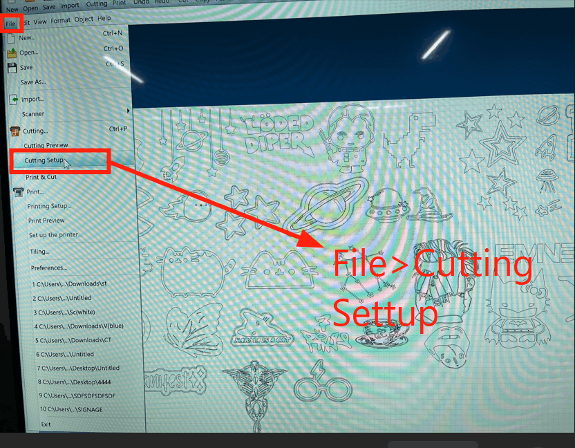
Once you've finished extracting the image outlines, start the cutting process by pressing Ctrl + P or by going to File > Cutting Setup.
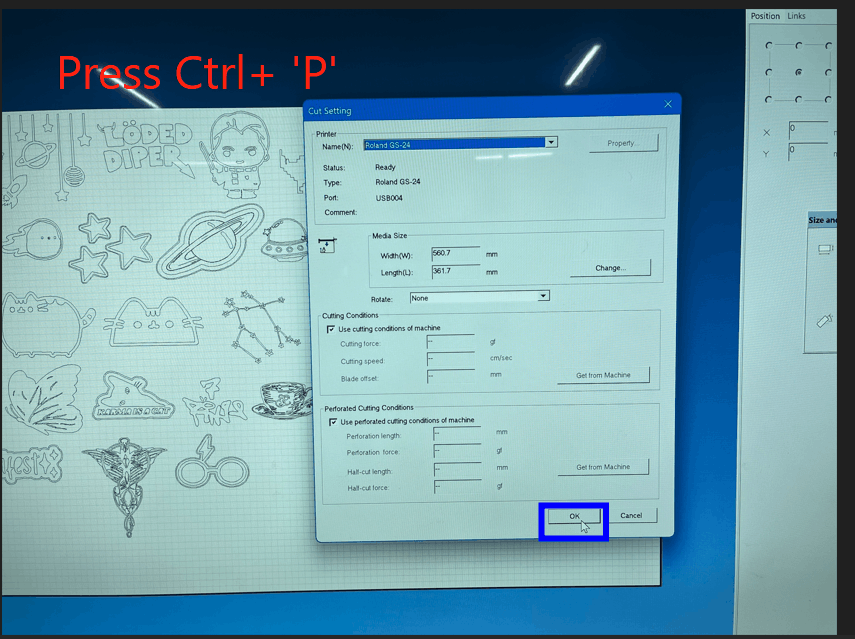
Then, when the cutting settings window appears, click OK to proceed.
The machine will now begin cutting your design onto the vinyl sheet.
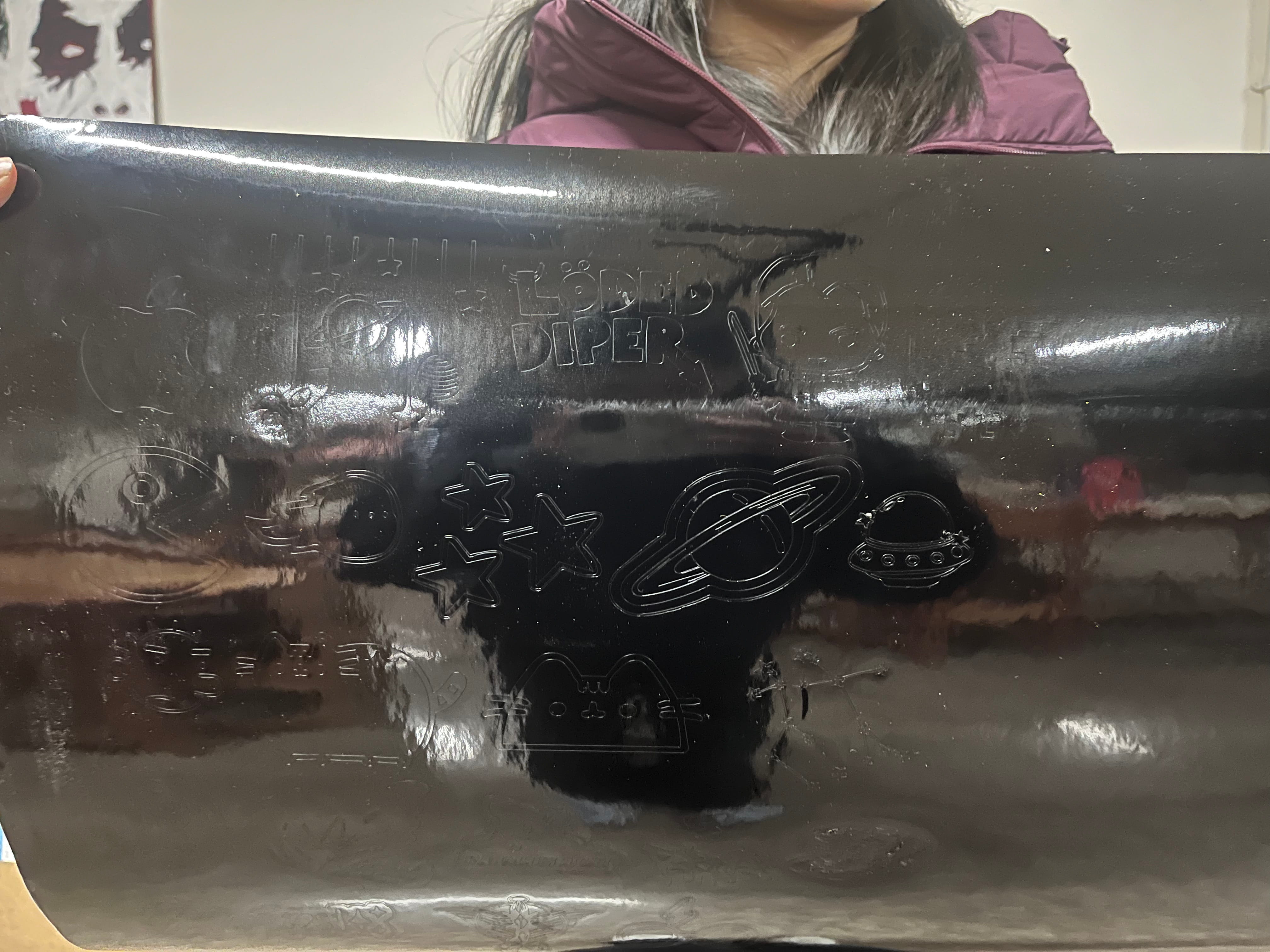
It took a while for the machine to finish cutting all our stickers, but this was when it finally finished cutting the stickers on the vinyl sheet.
Weeding
Weeding is the process of carefully peeling away and removing all the unwanted vinyl from a freshly cut sheet, leaving only your actual design stuck to the backing paper.
Weeding took forever 😭 because most of our designs were super detailed. The hardest one was definitely the Evenstar necklace from LOTR; those tiny ring parts were really tricky to clean up.
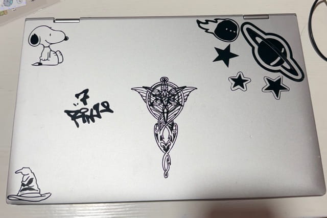
Anyway, here are all my stickers after about two hours of cutting and weeding. Some of the stickers were for my friends, and I kept the rest to decorate my PC and add a bit of character to it.
 (1).png)
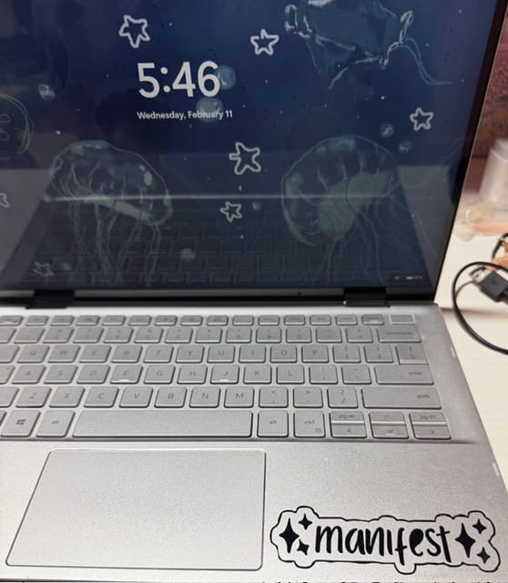
These were all the stickers I used for my laptop:
Reflection
This week was a fun designing week especially learning how to use the vinyl cutting machine and I had a lot of fun and learned a lot! That's all for week 3!