Week 15: System Integration
Assignment
Design and document the system integration for your final project.
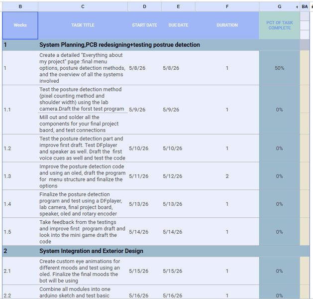
I started off this week by making this schedule for my final project tasks in google sheets so that I could be able to manage my time better:
3D deisgning final project:
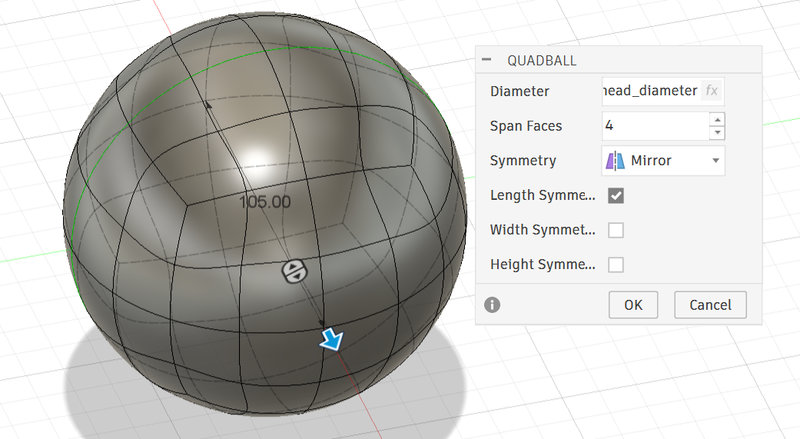
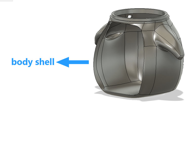
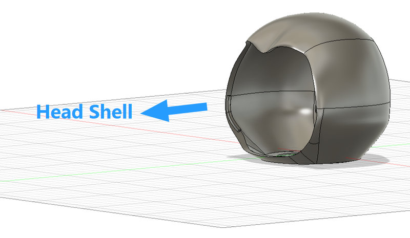
I used Fusion 360 to 3D design the desk bot, which is supposed to look like a penguin. I also considered using Blender, but since I’m more familiar with Fusion, I decided to stick with it. I first created the overall silhouette using a quadball in Fusion Forms, then kept adjusting and shaping it until I got the look I wanted.
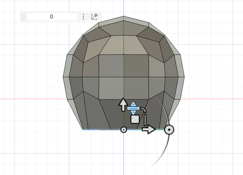
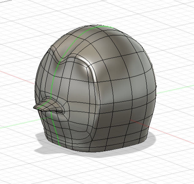
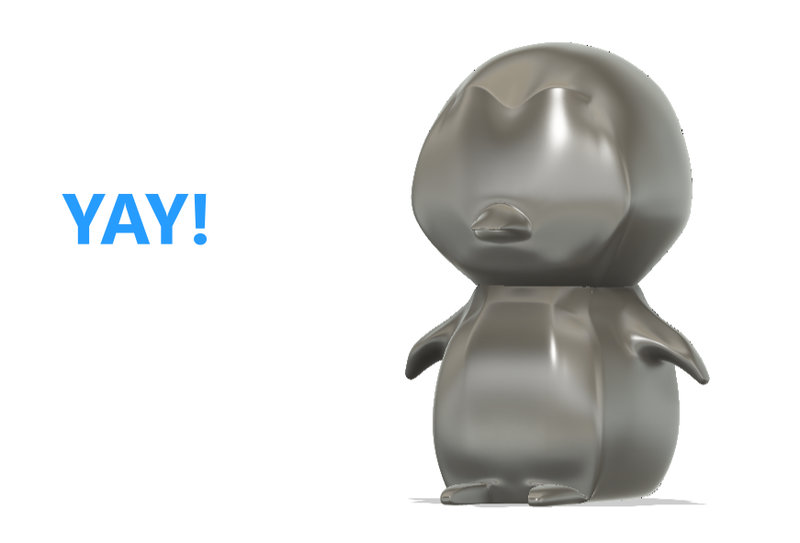
Then after getting the overall shape of the penguin in Forms, I switched back to Solid began working on the details such as the holders and cutouts for electronics.
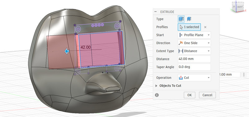
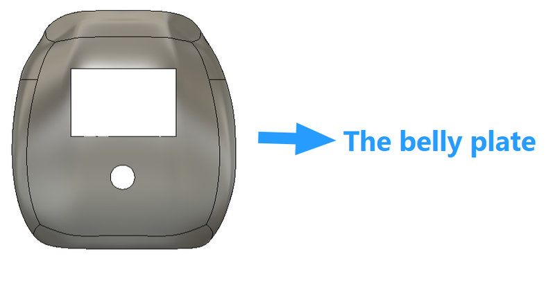
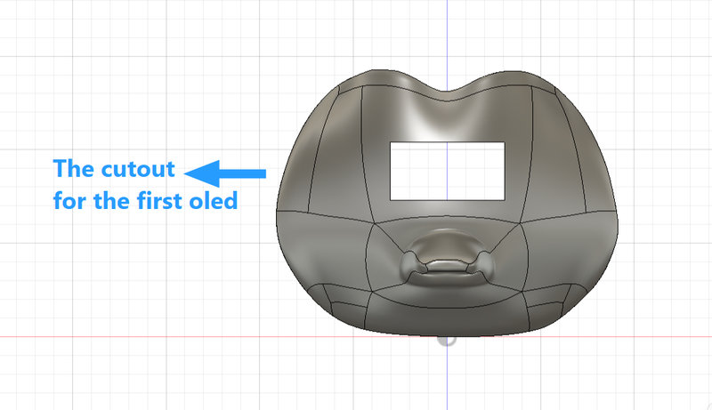
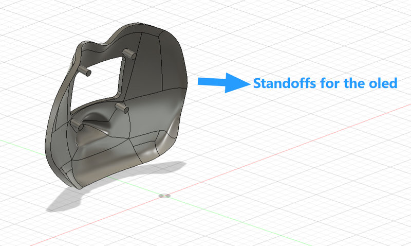
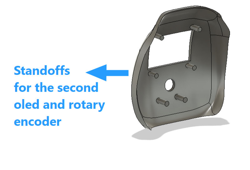
All front shells/plates are for mounting the exterior components. There are two front plates, one for the head and the other for the belly. Both are meant to mount a 1.3 in oled screen but a rotary encoder will also be mounted on the belly plate in addition.I created the frame cutouts on the plates and then the stadoff which are like poles that go through the holes on the module and then a similar cap will be used to sort of lock the module.
This is the belly plate:
And this is the face plate:
Mounting external components:
Mounting Internal components:
All internal components like the pcb board, rtc, speaker etc will be mounted on the back shells using stadoffs as well.Right now, I am working on the internal mounting part.
Where Everything Fits Inside the Penguin
Right now, it might be hard to imagine how all the electronics come together inside the 3D printed shell.This is a labelled image of how everything would come together:
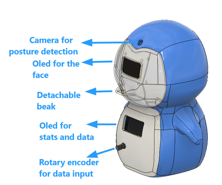
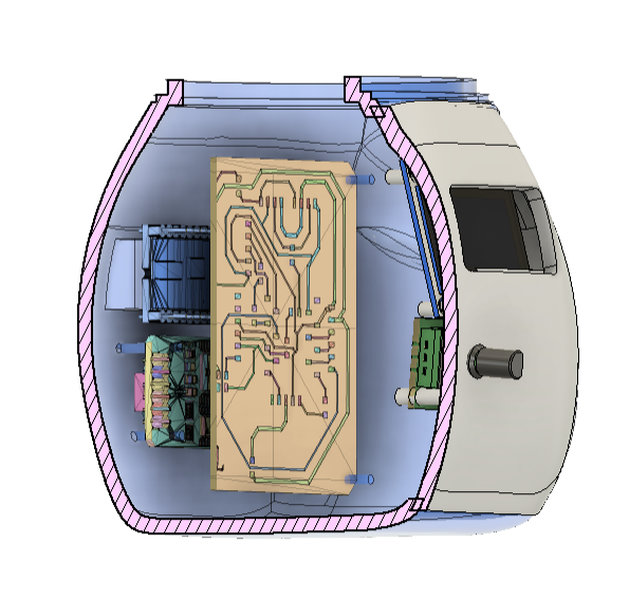
How the components fit together is more detailed in my final project development page. You can check it out there as well.
Working on the pcb board:
This week I was also able to mill out my board and solder all the components 😮💨
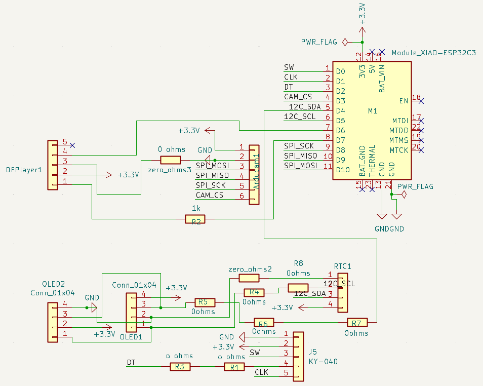
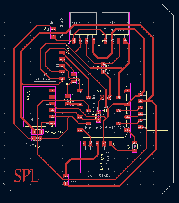
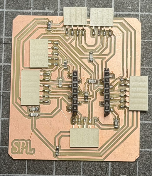
I modified the previous versions of board in Kicad.Initially it had short circuits and ground power issues but then I modified that and hopefully it works🤞.This is the schematics and the pcb.
Milling the pcb:
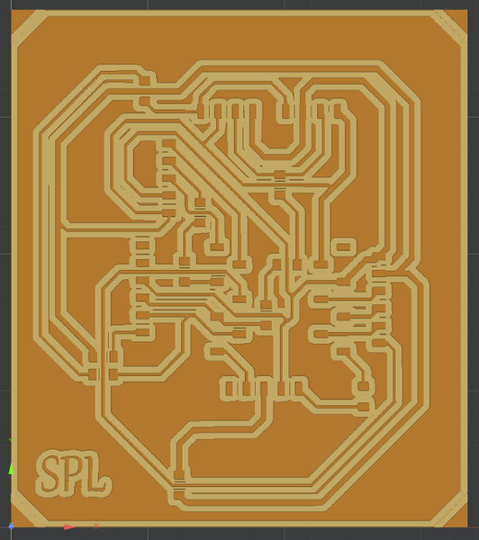
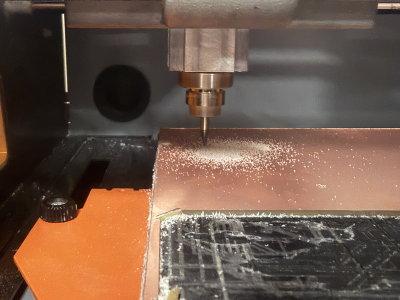
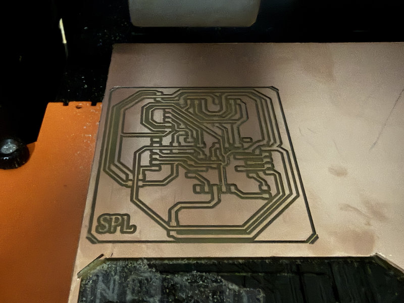
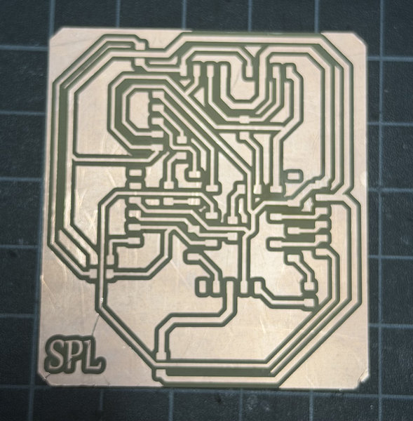
After soldering 🥳
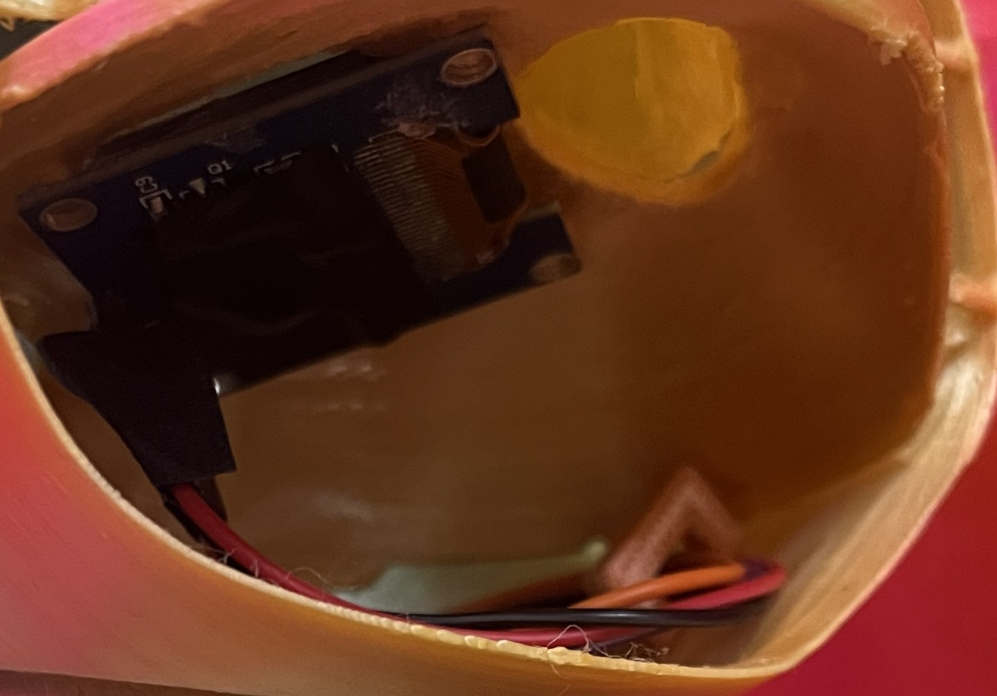
Okay progress update, I have been able to print the first draft of my project, and I tried mounting all the components inside. This is the interior of the penguin, the belly where you can see the PCB and the RTC and Dfplayer are behind the PCB mounted using the standoffs just like in the design and the oled is mounted on the detachable belly. Same goes for the oled on the detachable face
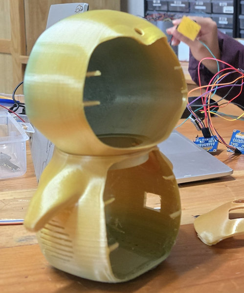
This is what the first printed draft looks like:
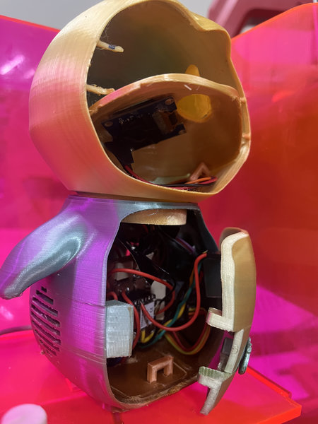
All wires will be routed along the inner walls and secured using 3D-printed 'C' clips that act like cable gutter channels.
Reflection:
I got to work a lot on my final project which has been really progressful and helpful for me!
Thank you bye! (❁´◡`❁)