Week 12: Mechanical design
Group assignment:
- design a machine that includes mechanism+actuation+automation+function+user interface
- build the mechanical parts and operate it manually
- document the group project and your individual contribution
Individual Assignment
- Document your individual contribution
Learning Outcomes
- Work and communicate well in a team
- Design, plan, and build a machine
- Identify and solve technical problems
- Find ways to improve the design
Requirements:
- Recorded the machine building process on the group page
- Documented my individual contribution on my own website
- Linked the group page to my personal page and my page back to the group page
- Showed how the team planned, divided tasks, and completed the project (Group page)
- Explained the problems faced and how the team solved them (Group page)
- Listed possible improvements for the project (Group page)
- Included the design files on the group page
Group assignment:
For this week’s group assignment, we decided to build a CNC pen plotter, and I was mainly responsible for designing some of the machine parts and the casing in 3D. Overall, the experience taught me a lot, especially about paying attention to detail, being precise, and staying calm even when things got stressful. And as much as it was stressful sometimes, it was really fun too.
You can access our group assignment here for more details.
Individual Assignment
Idea
After the three of us spent quite some time brainstorming different possible ideas for the group assignment, we decided to build a CNC pen plotter 😆 . We decided to go with this idea not only because our lab didn’t have one, but also because we thought it would be fun and would cover all the requirements for this week.
Me and azhim Sonam Pema were in charge of 3d designing all the parts for the CNC pen plotter 😮💨
CNC Pen Plotter
A CNC Pen Plotter is a machine that holds a pen and moves it automatically to draw designs on paper.
- Mechanism: The belt, pulleys, frame, gears and pen holder that physically guide and support movement
- Actuation:Stepper motors for X and Y axes ( for left/right and forward/backward) + Servo motor for Z axis (pen up/down)
- Automation: Arduino Nano running the firmware reads G-code commands and controls all motors automatically without human intervention
- Function: Draws designs, images, and text on paper by moving a pen precisely across a surface
- User Interface: G-code sender software and Inkscape with Gcodetools plugin to convert images into machine instructions
- The machine has a rigid frame, belts, rails, and a pen holder that physically support and guide movement
- One stepper motors control the X axis (left and right movement) by turning belts that pull the pen carriage
- One stepper motor controls the Y axis (forward and backward movement) by moving the entire gantry on rails
- A servo motor controls the Z axis by rotating a small arm that pushes the pen down onto the paper or lifts it up
- An Arduino running GRBL firmware acts as the brain, reading G-code instructions sent from a computer
- You create a design in software like Inkscape, which converts it into G-code (a list of coordinates and commands)
- A G-code sender program transmits those instructions to the Arduino over USB
- The Arduino tells the motors exactly when and how much to move to trace every line of your drawing
- The pen draws when the Z axis pushes it down and moves across the paper, it lifts when moving between lines
- The result is an automatic and precise drawing of any design you create on your computer
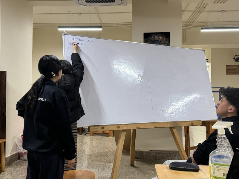
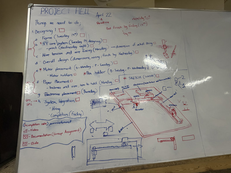
Before working on the plotter, we planned out a road map for making the CNC plotter so that we could finish all our tasks on time and divided the roles amongst us. Me and azhim Sonam Pema divided the parts of the machine to 3d design. I was mainly working on the electronics and motor placement holders.
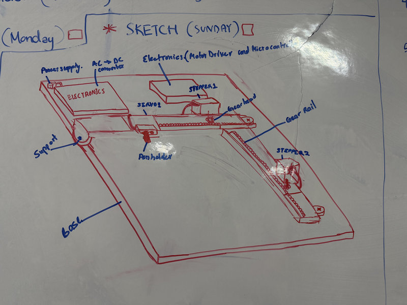
This was a rough sketch of the initial deisgn of the CNC plotter we tried to make:
3d Designing In Fusion:
For my task, I decided to use Fusion 360 to design the parts I was working on.
I referred to this tutorial to design the pcb casing. I wanted the casing to be able to easliy open and close just like a container.
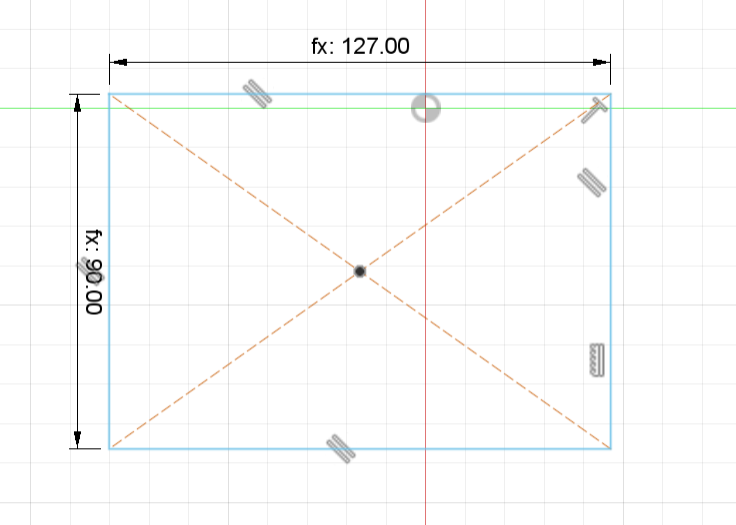
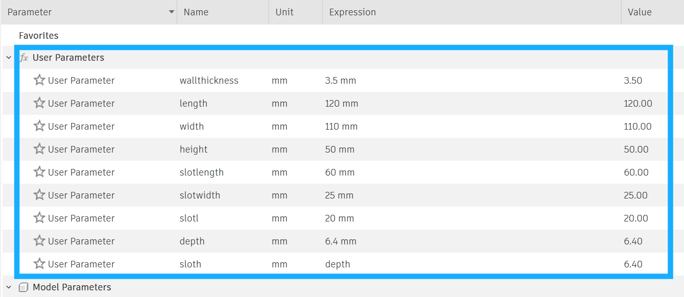
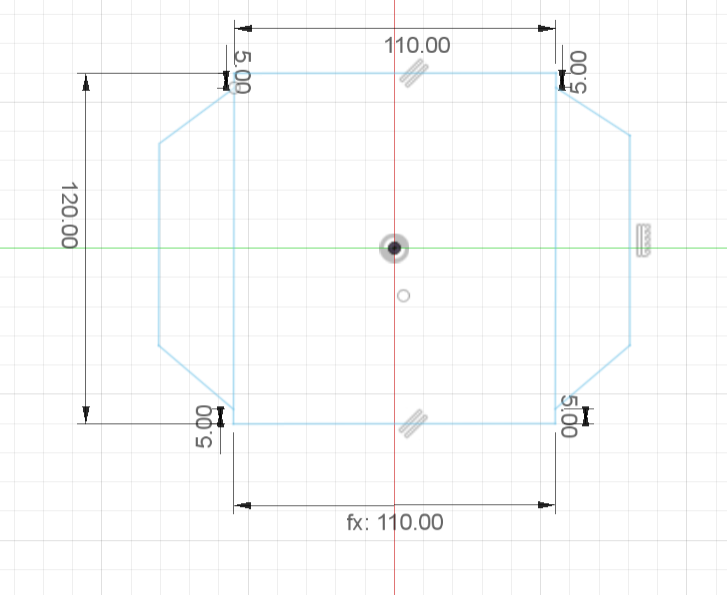
We didn't know the exact measurements of the pcb that time so I used parameters to design the casing:
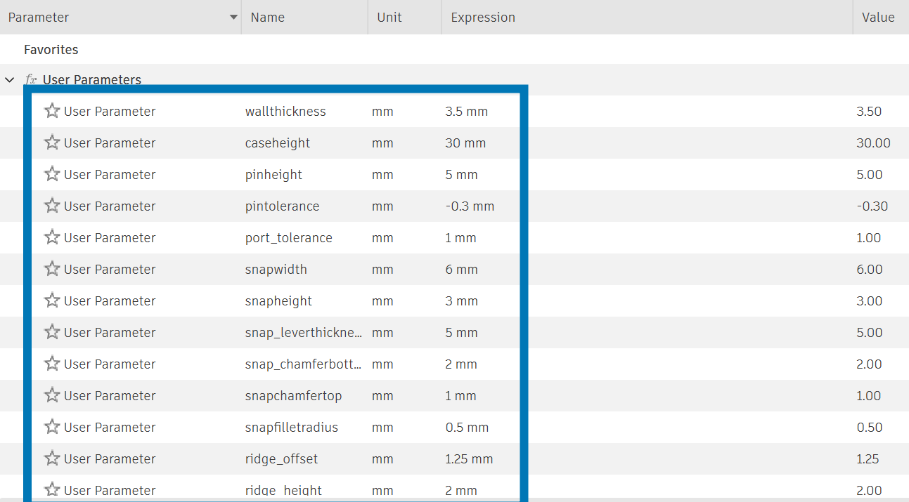
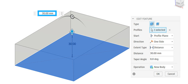
I used paramters to sketch out the case and extruded the case.I imported an arduino nano take it as a reference to deisgn the case since we were using Arduino Nano as our main microcontroller.
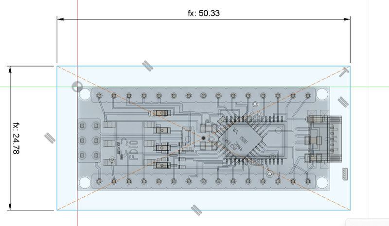
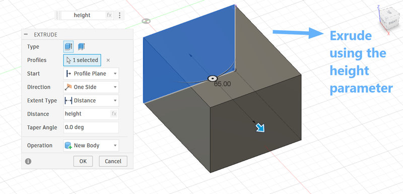
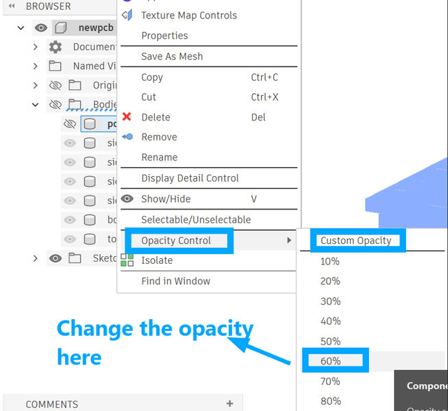
To make it easier to view the inside of the casing, I reduced the body opacity to 60% using the opacity control after right clicking on the body I wanted to adjust.
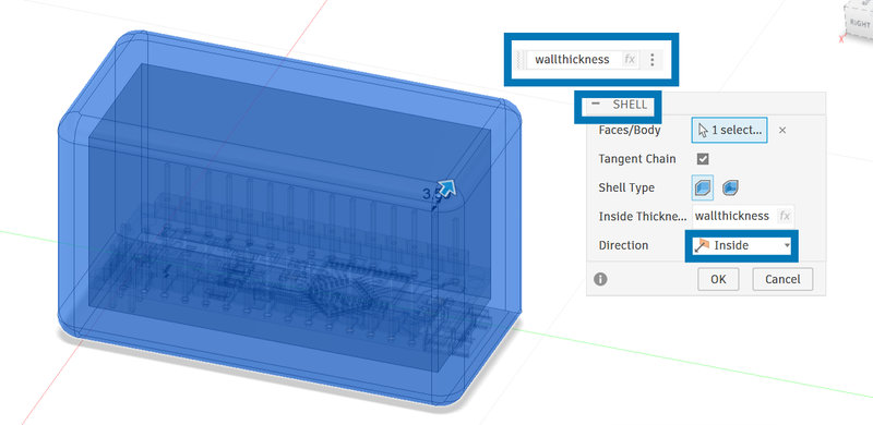
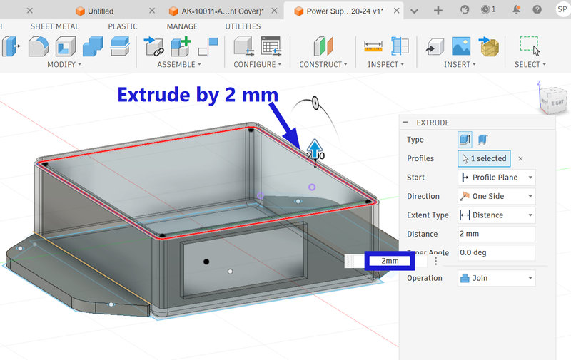
I had to extend the dimensions of the body according to the estimated length and width of the pcb and then I used the shell tool to hollow out the box with a thickness of 3.5mm
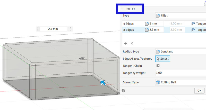
I used the fillet tool to round all the sharp corners and edges.
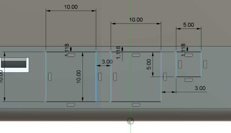
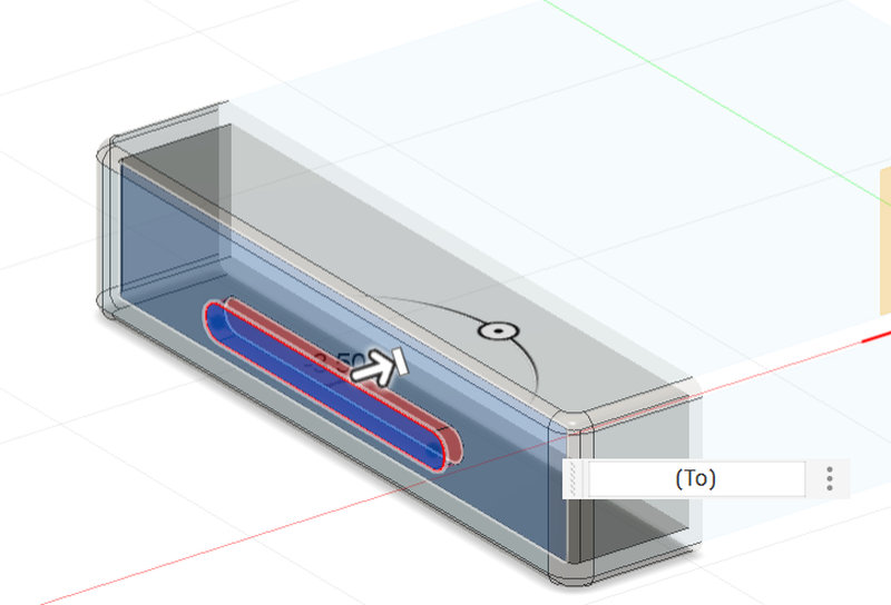
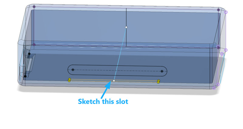
I cut out holes for the wiring, with 2 of them being 1cm x 1cm and the other one being 0.5 cm x 0.5 cm.And I cut out a long slot just for decoration.
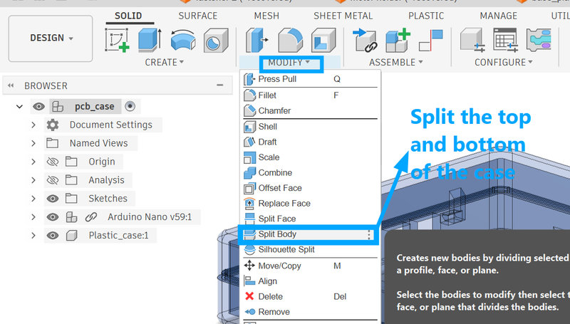
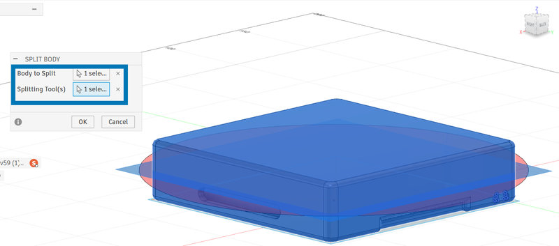
Then, split the body. The top part will be the lid and the bottom part will be where the pcb will be placed.
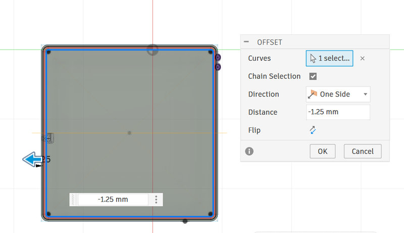
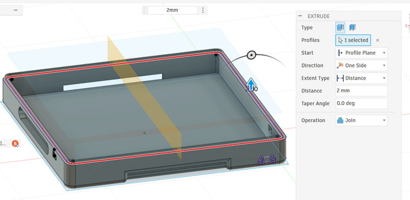
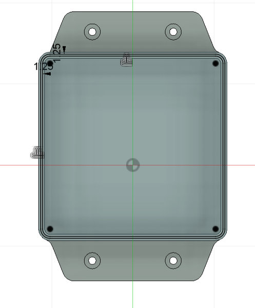
I used the Offset tool and selected both the inner and outer edges, then offset them by -1.25 mm. This created a sketch of a ridge in between, which I then extruded to form the ridge for the container.
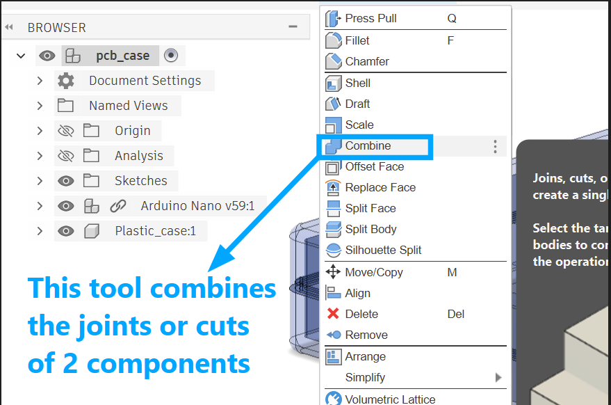
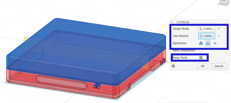
Then combine the two bodies by setting the top body as the target and the bottom body as the tool, and choose the Cut operation. This allows the ridge on the bottom body to create a matching groove in the top body, so the enclosure can fit together and open and close like a container.
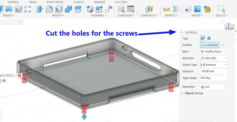
When placing the casing on a wooden base, it needs to be fixed so it doesn’t move. So, I sketched and cut holes in the base of the container for screws to secure it.I kept the diameter as 2.5 mm for the timebeing using parameters.
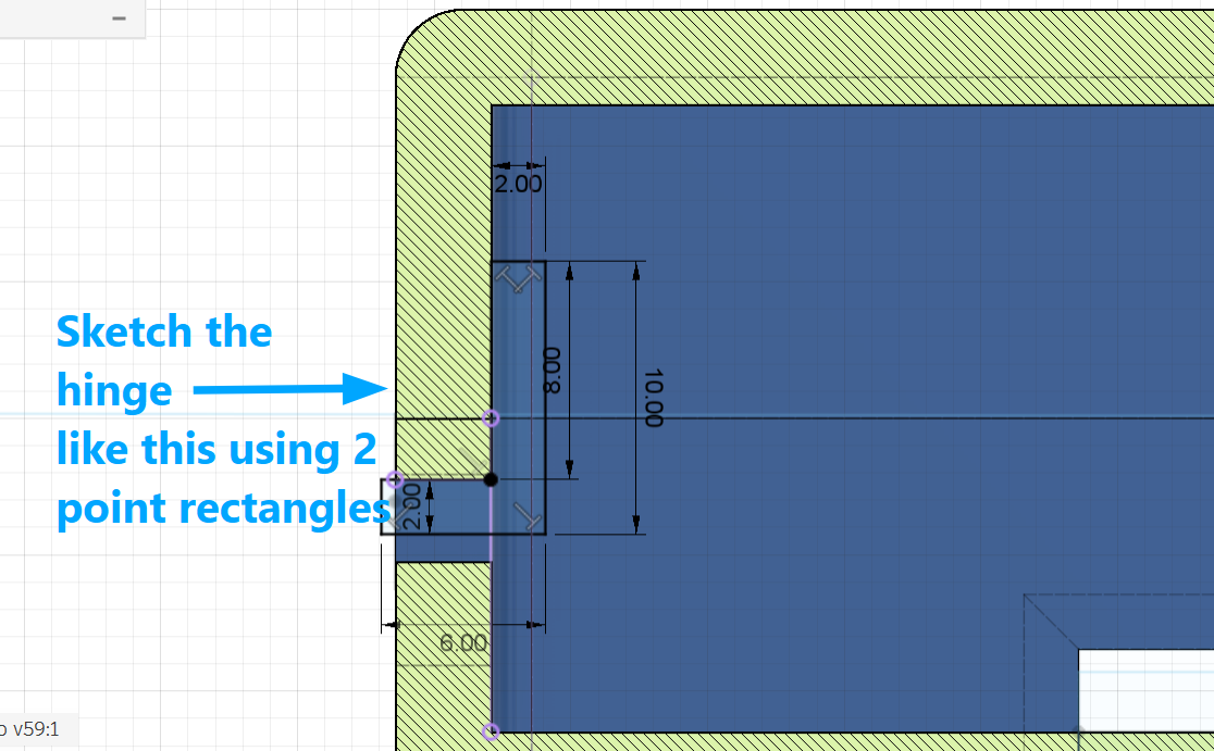
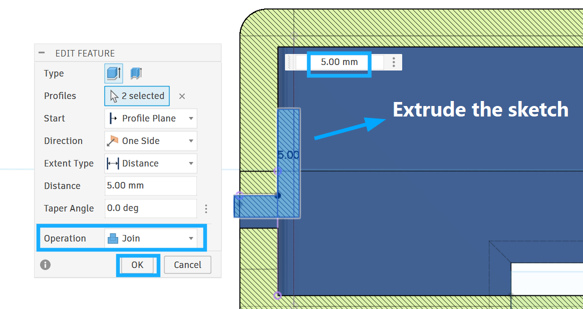
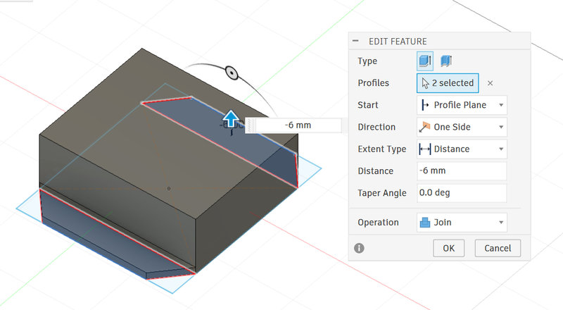
Following the tutorial, I created a sketch of a hinge for the lid. This hinge fits into a slot in the bottom part of the container, making the opening and closing more secure and stronger. Chamfer them by 2mm using the chmafer tool form the top tool panel.
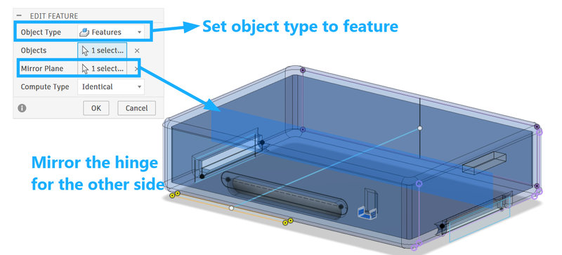
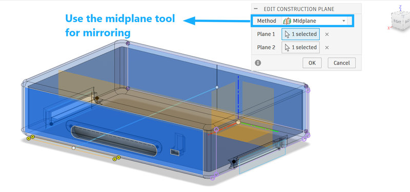
I created three more hinges by mirroring them to the other side of the container. To do this, I used a midplane construction plane by selecting two sides of the container, placing the plane in the middle, and using it as the mirror plane.
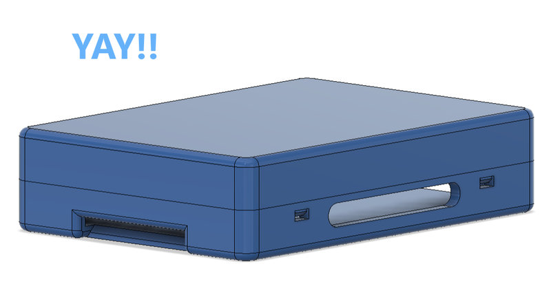
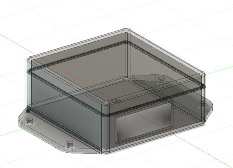
And, yay! The first case for the pcb was done 🥳
Now for the second case which is for the AC to DC converter, I made it similar to the first case but I changed the dimensions and made two wings for the bottom to secure it with screws.
These are the new paramtere I used for the new case:
This is what the second case looks like:
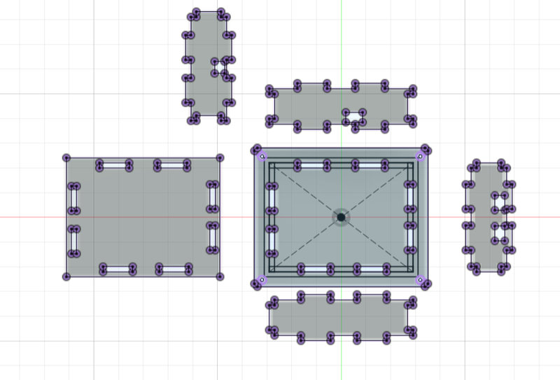
Change of plans, since the 3d printer was giving us a hard time with printing all the compoennts for our plotter I had to resort to laser cutting the pcb case using acrylic. And we replaced the AC to DC converter with 5V adapters, so we didn’t need a second case after all. These are the parameter I used for my design:
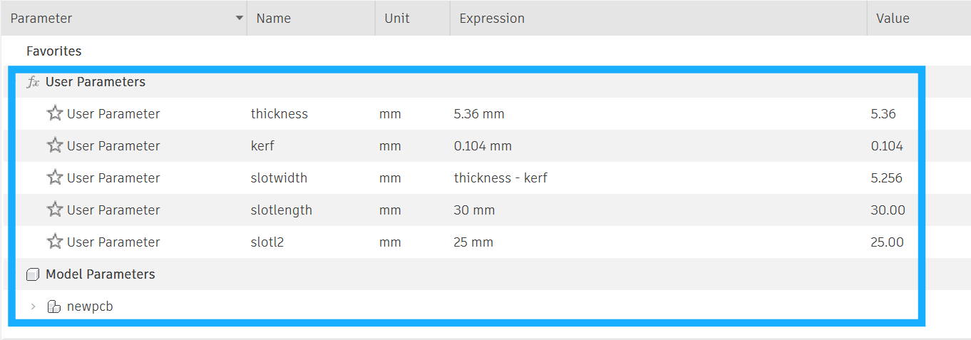
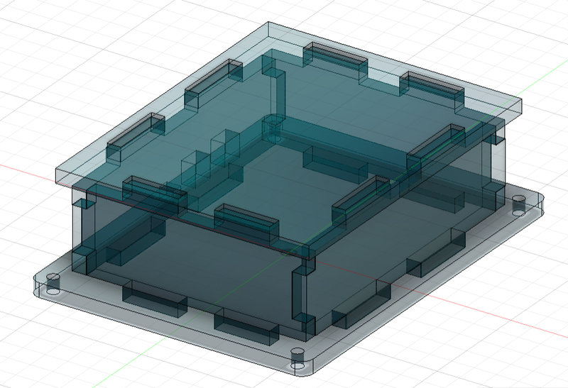
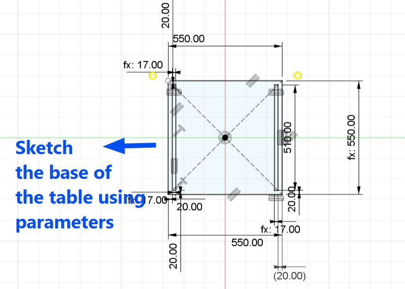
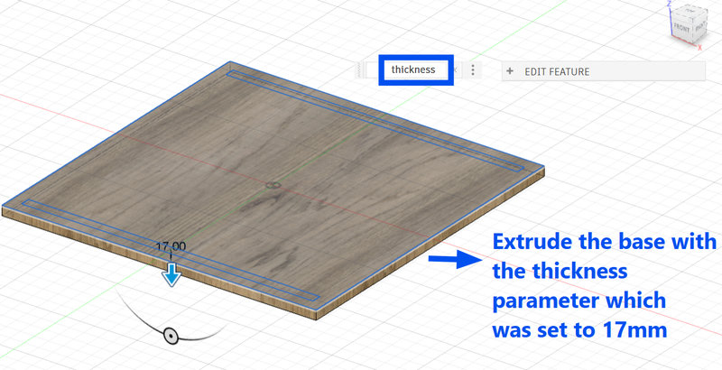
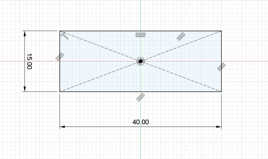
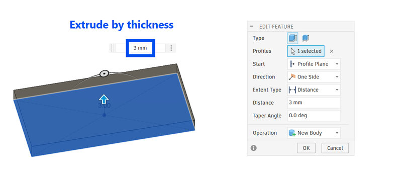
Then using the parameters, I sketched the base of the pcb case and then extruded each wall as a new body.
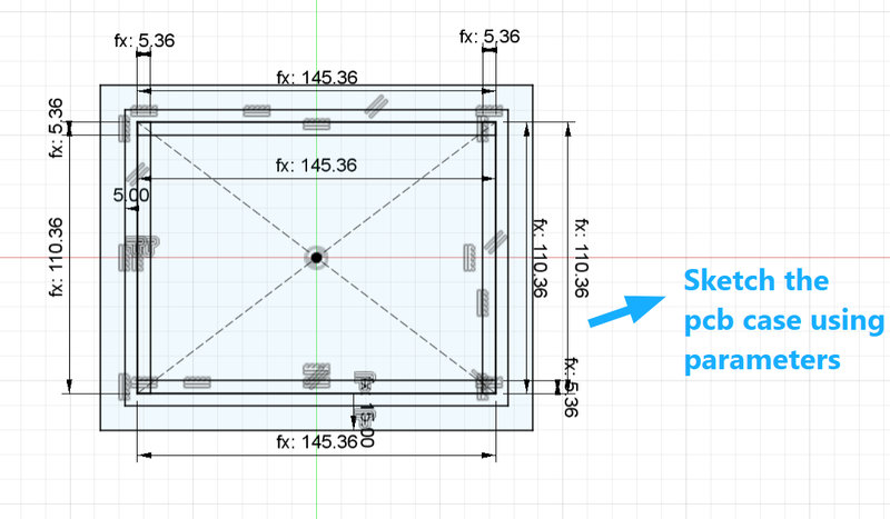
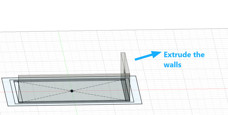
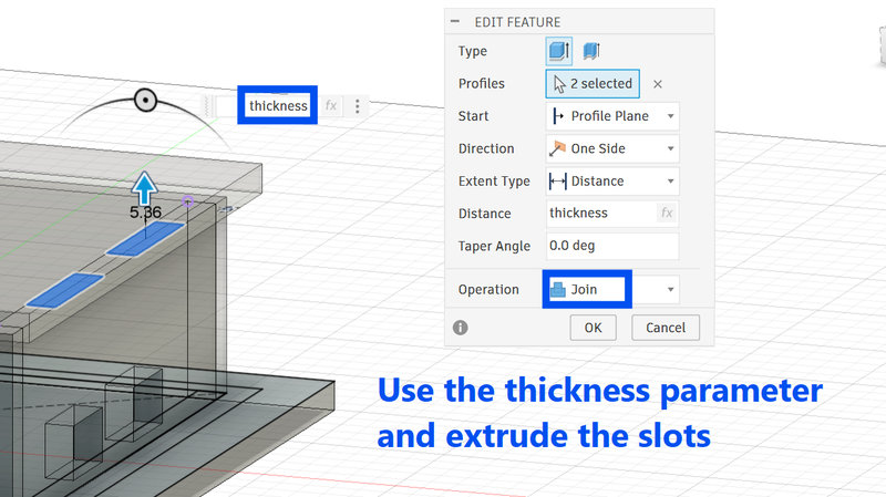
Sketch slots and extrude on each side as well, since this case will be assembled using a press fit design. The slots for the longer sides are 30mm x thickness while the slots for the shorter walls are 25mm x thickness, and the thickness of the acrylic I was planning to use is 5.36mm.
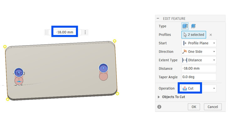
For the sides that need to fit into the slots, cut matching slots on them. I used the Project tool (press P) to copy the exact size of the slot by selecting the side to project from. Then I extruded the sketch and set the operation to Cut.
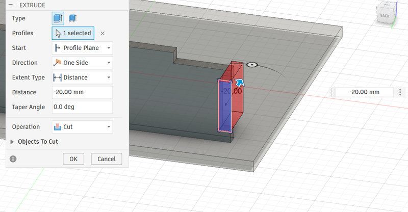
Next, I had to think about slots for the wires. I added two slots sized 15 mm × 10 mm on one side and placed two more on the other walls. Then I extruded these slots and set the operation to Cut. Later, I found out that the slots were on the wrong sides, so I had to redesign the case..
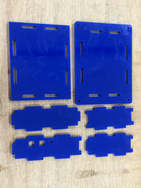
This is the final look of the case:
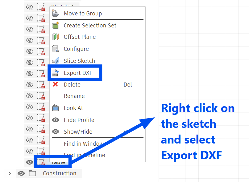
To laser cut the design, the sketch from the 3D model needs to be exported as a DXF file so the machine can read it.
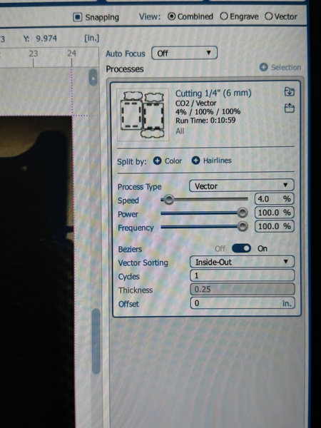
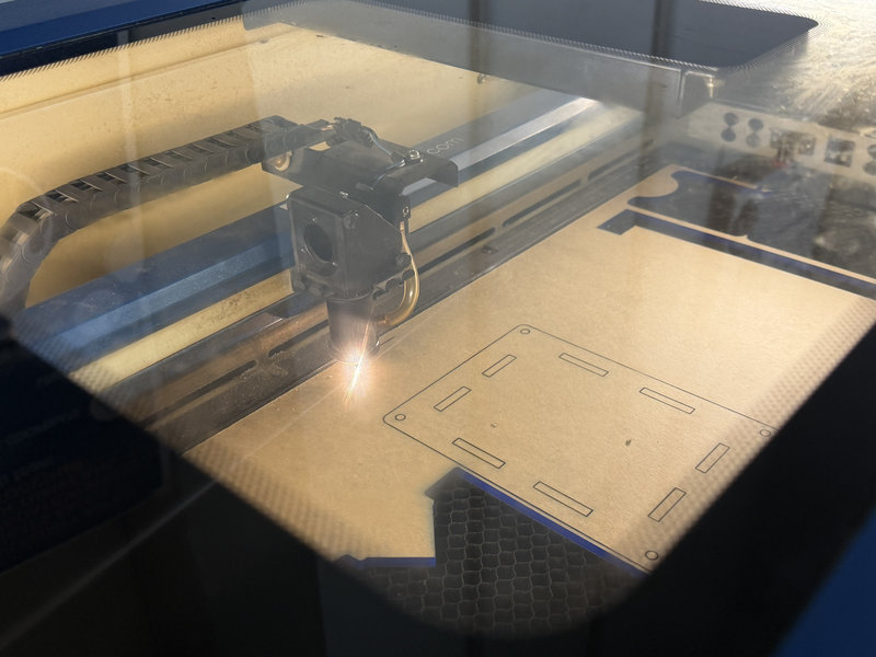
Laser cutting:
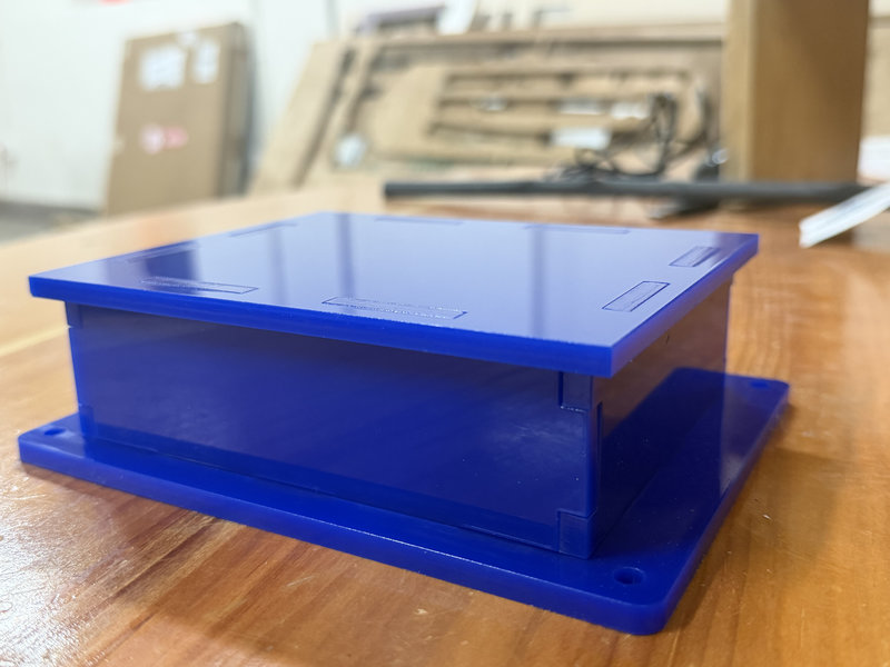
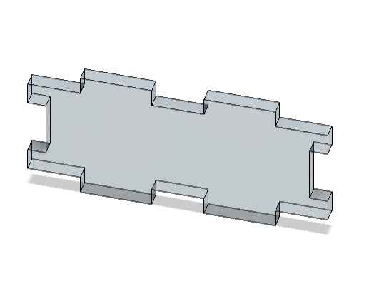
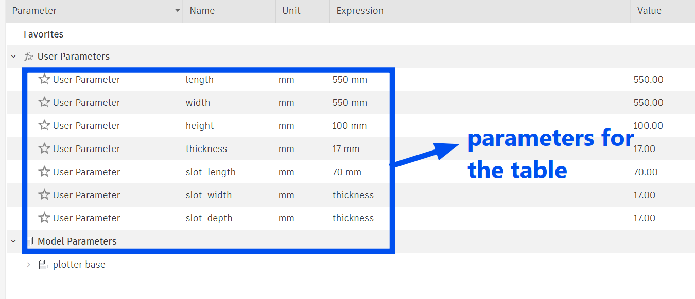
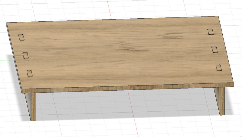
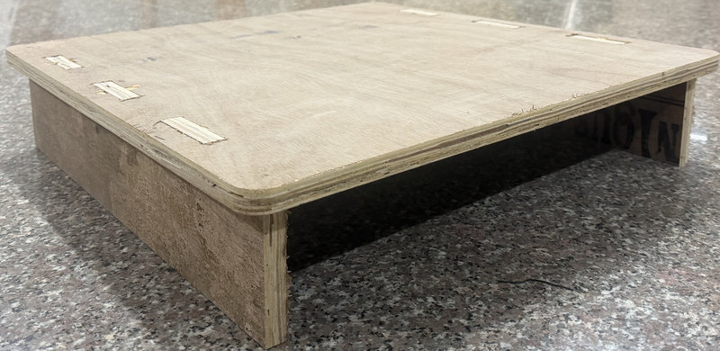
Next, I had to work on the pen plotter base as well. I made a mini press fit table in fusion:
These are the parameters for the table:
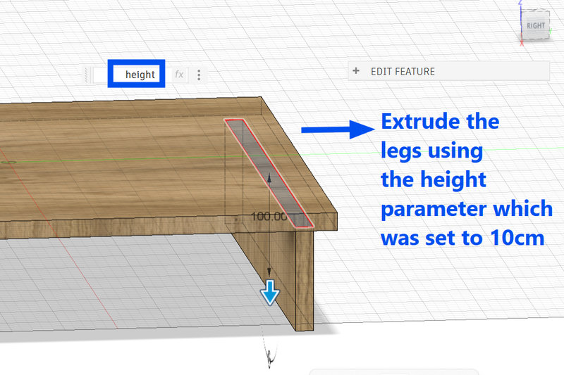
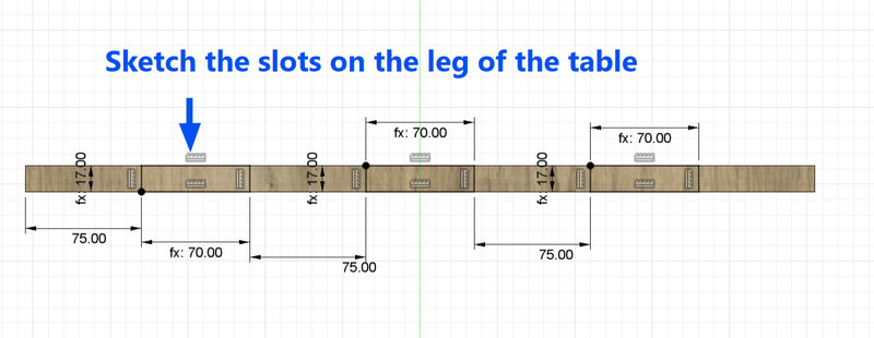
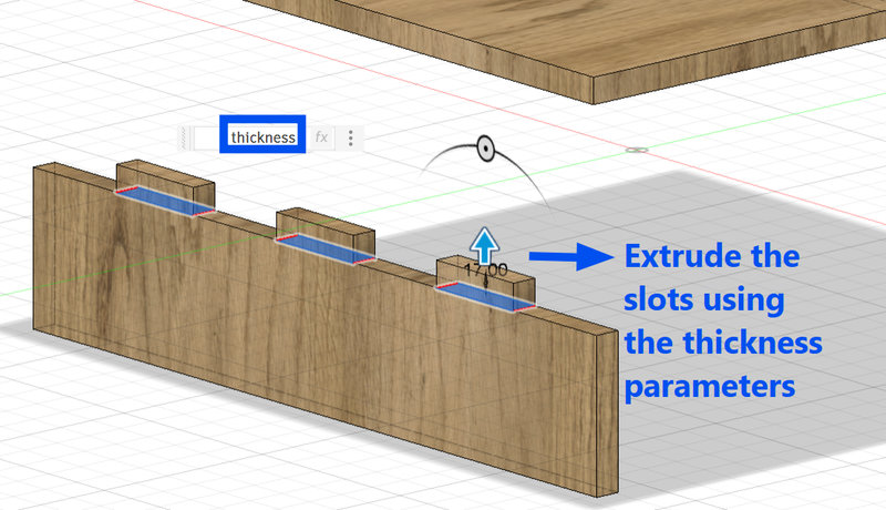
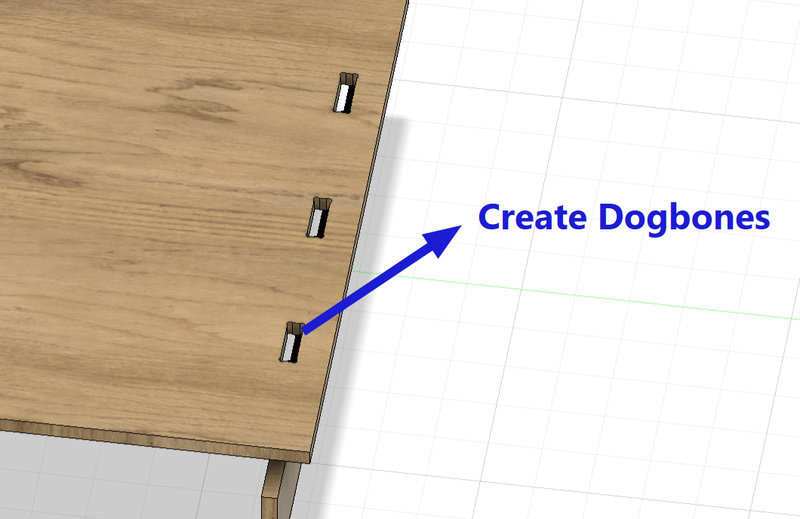
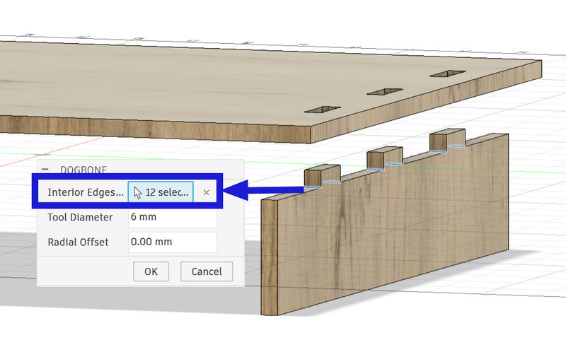
This is the final look of the table:
Using the CNC machine:

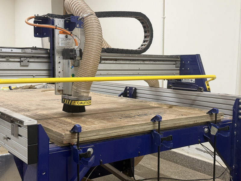
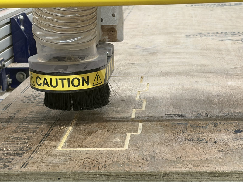
I also had to design a few parts of the machine:
I deisgned the bearings for the cnc plotter which will be used as wheels and the cover 5mm bearings for the pen holder and the intersection base plate the y-axis extrusion would sit on, since we didn't have those kinds of v-slots:
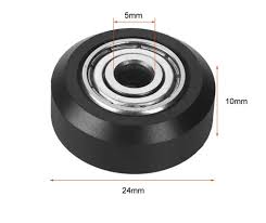 Image source
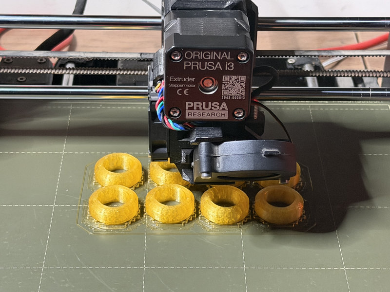
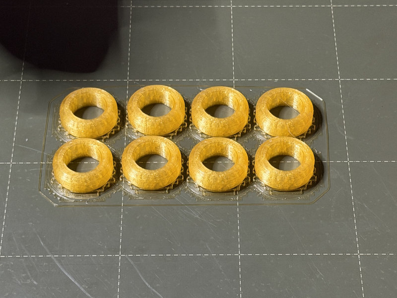
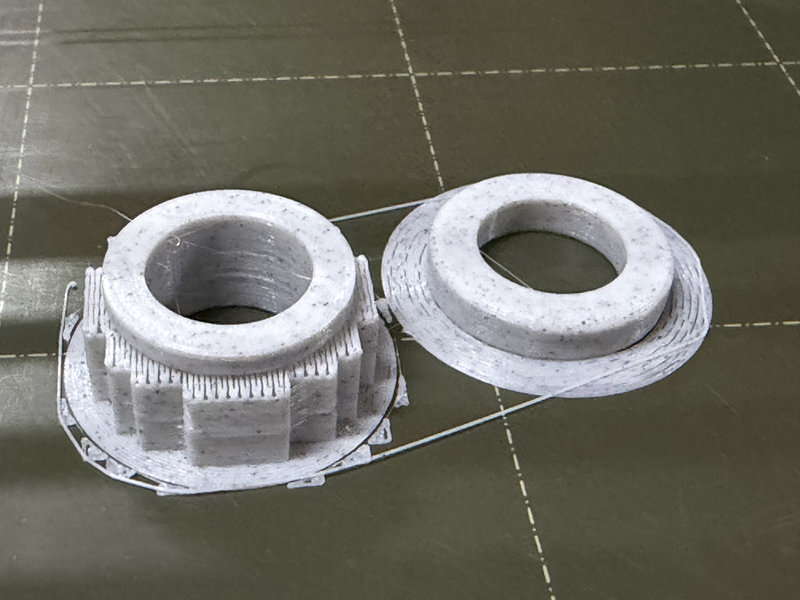
While working on the bearings for our CNC pen plotter, I needed them to smoothly move along the groove of a 20×20 mm aluminum extrusion, so I designed them in Fusion. Our instructor suggested shaping them like train wheels so they could glide better.
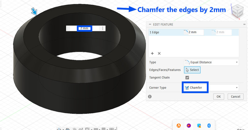
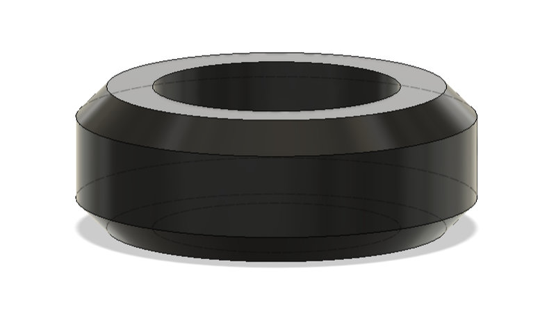
I designed the bearing with a V-shaped profile so it could sit properly in the groove. I matched the width of the bearing to the groove width, which was 5.4 mm, to ensure a smooth fit. Then, I chamfered both edges by 2 mm, creating angled sides that form the V-profile, similar to train wheels, allowing it to run smoothly along the extrusion.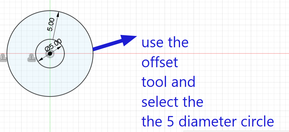
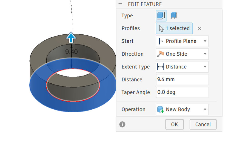
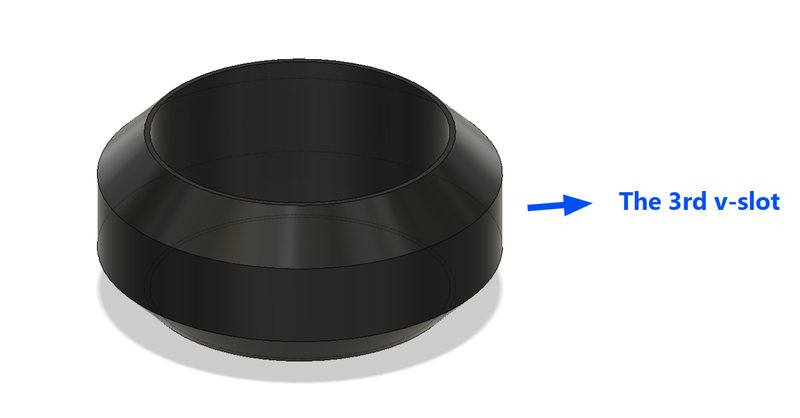
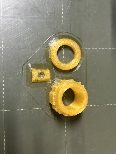
The penholder needed a third wheel which had a smaller diameter than the other two v-slots, so I decreased the diameter by 3mm andd since the bearing ended up a bit loose, I decreased the slot for the bearing from 16.2 mm to 16.1mm.
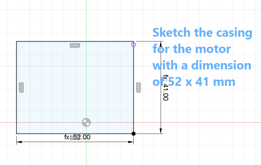
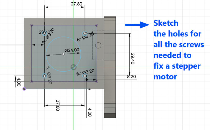
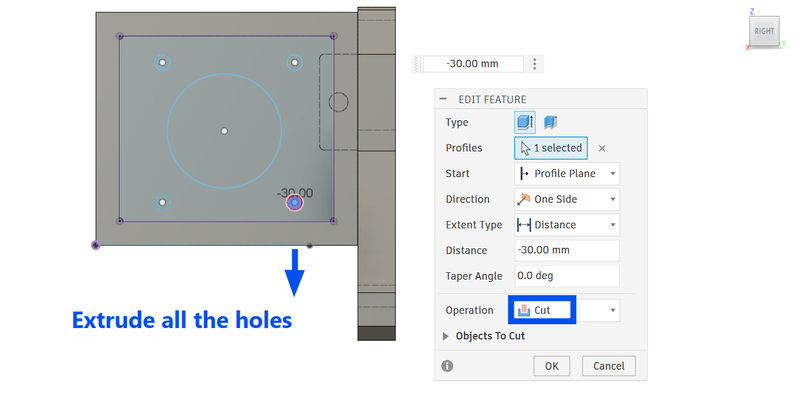
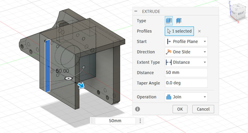
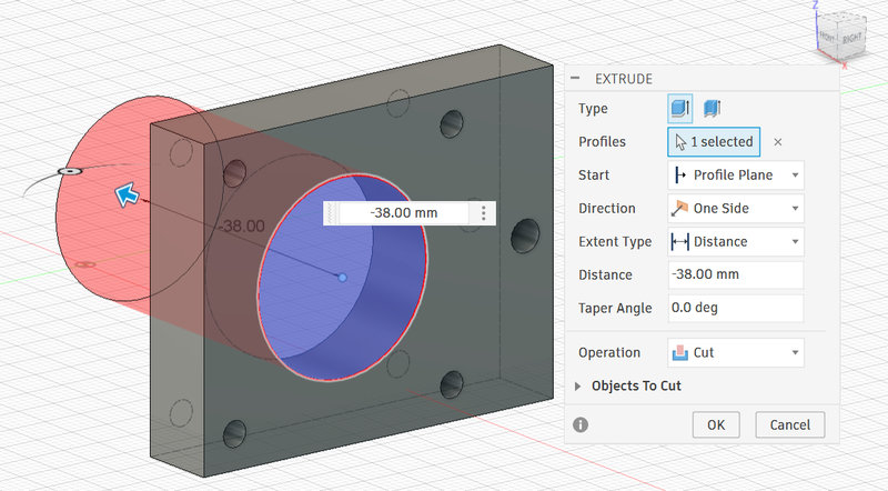
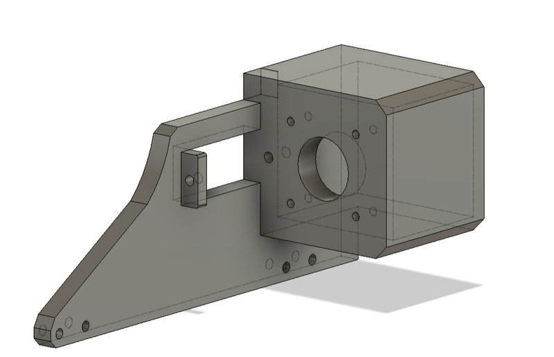
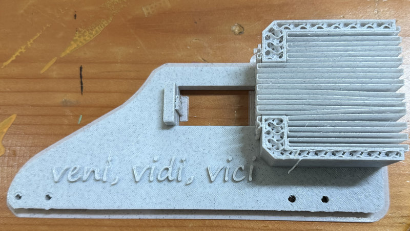
Next,I had to design the motor holder for one of the stepper holders which was supposed to be 3d printed.We were using the Nema 17 stepper motor, so I had to measure the motor to get the dimensions right especiallyb for the screws. Then I chamfered the edges by 5mm to make it look nicer.
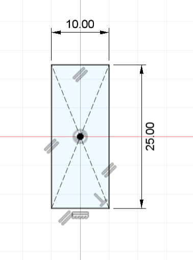
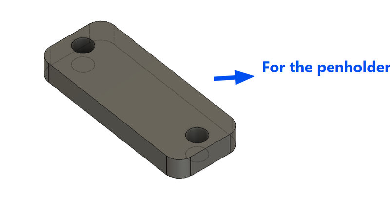
The CNC plotter also needed a way to hold the belts, so I designed a small rectangular plate like part for it. The belt gets clamped underneath it, while the rectangle sits on top and is screwed down onto the base to keep everything tightly secured. I deisgned two for the intersection top base plate and one for the pen holder.
I measured the slot on the base plate from which the belt is supposed to go through from so that the dimensions don't end up inaccurate.
This will clamp the belt for the x-axis on the base plate.
And this will clamp the belt that goes through the pen holder:
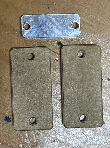
I used a 4mm white acrylic for the rectangles:
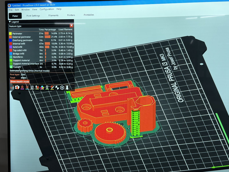
3d Printing:
The 3d printing part took way longer than it should have and it was also the most time consuming part all week especially because our printer was giving us a lot of problems 😫 like filament not properly extruding out, and it took us quite a lot of time before we could gather all the printed parts and assemble the parts.Maybe we should have actually laser cut some flat components like our instructor suggested to save time 😅
On top of the 3d printer not properly working we had to reprint several parts because of some pieces not fitting correctly or the screw size being wrong or the dimensions not being right. So we had to design several parts again and reprint them.
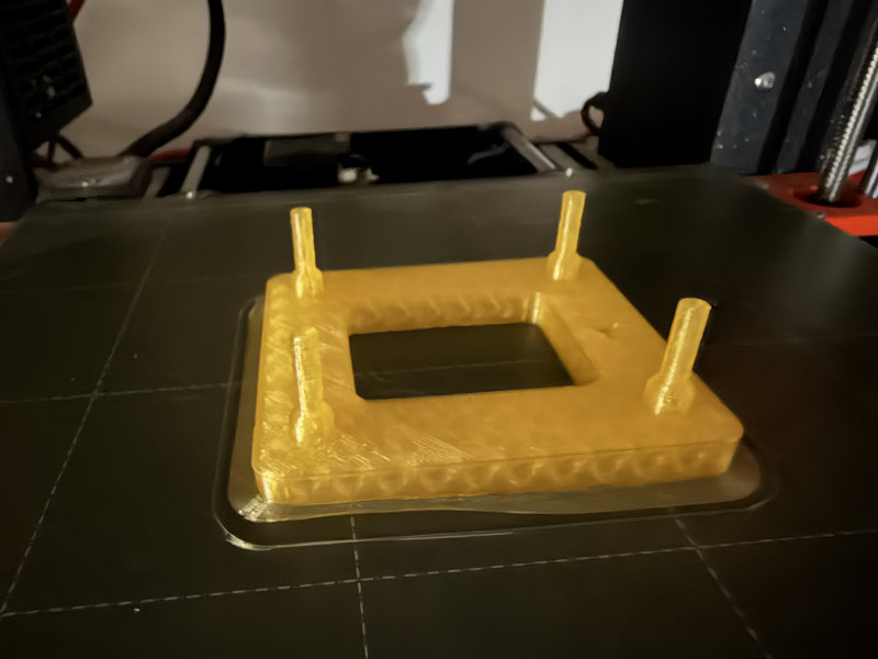
Before finalizing the parts, we tested fit and tolerance by printing small sections of the design (such as screw holes, motor mounts, and wheel slots). We noticed early issues such as screw holes being too tight for M3 screws, motor mounts not aligning properly with the Nema 17 holes, and V wheel spacing being slightly too narrow for smooth movement on the aluminum extrusion. And the base plate failed multiple times because the hole diameter for screws was too small by around 0.2 to 0.4 mm, and the motor holder had an offset issue that caused misalignment with the belt path. Each time we reprinted, I updated the Fusion 360 parameters by increasing hole tolerances, adjusting offsets for motor alignment, and slightly increasing clearances between moving parts. This was more of a trial and error process and we ended up reprinting the base plate 7 times before we got it right 😭
After each print, I changed the parameters of the design for the mounting holes by 0.2 mm after noticing that M3 screws were too tight in the first prints. I also adjusted the clearance values between moving parts such as the V wheel slots and the aluminum extrusion to allow smoother movement.
Some parts weren't fully printed as well because of some temperature problems that caused the printer nozzel to get blocked and stop extruding filament mid way. The frame, especially the one with the motor holder was the one that took the longest to print and the printer was not really helping 😭
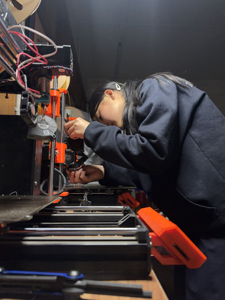
Assembling:
After printing almost all the parts that took like forever, we started assembling all the components because the faster we could assemble all the pieces, the sooner we could test the machine and find out more problems with our design.And after assembling some pieces we did find out a lot of problems like pieces that don't fit correctly especially the poles that go into the base plate 🤦♀️ and the v-slots weren't gliding properly along the groove. It took a lot of time in finding the right screws that fit into our pieces as well 😮💨.
We had to turn the whole lab upside down to find the hex nuts and screws we needed while assembling 😆. Here is a clip of us having a headache assembling while finding the right screws and running into new problems with our designs:
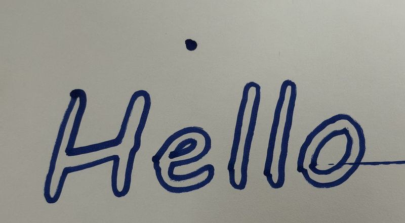
After finishing 90% of the assembly, we were able to test it out and yay it worked! ╰(*°▽°*)╯
If we continue developing this CNC pen plotter, we could improve the design by:
- Using proper toleranace testing before full scale printing to reduce wasted prints
- Switching more structural parts to laser cut acrylic to reduce printing time
- Adding limit switches (sensors at the near edges of movement) would improve the machine by making it more automatic and safer.This helps prevent the motors from pushing the pen plotter too far and damaging the frame or belts. They also allow the machine to automatically home itself to a starting position, which makes setup faster and more accurate each time it is used.
- For the machine to be more accurate, we need to add extra support for the far side of the Y-axis. The far side is already a bit higher compared to the near side, so as the pen plotter moves out to that side, the uneven height causes an uneven weight distribution. Adding a support on the bottom attached to a bearing that can move as well would help keep everything more level and balanced, making the drawings more precise.
That's all for this week. Thank you bye! (*/ω\*)