Software
This section contains the complete software setup for the project: the LinuxCNC install, the INI/HAL configuration, the genserkins DH parameter definition, the custom motion pipeline that talks to the Pico, and the VisMach visualization. This is by far the hardest part of the whole build, but also the most rewarding.
The Computer and OS
I started by picking up a cheap used computer (you don't need anything powerful for this). In my case, I found an HP Envy with an i5 7th gen, 12gb ddr4, and a 1tb hdd+ 128gb ssd for around $70. Then I downloaded the official Debian Trixie ISO, flashed it onto a USB drive with Rufus, and booted into it on the PC. I ran the installer, and once I was in, I gave myself root permissions.
Photo to add
Drop in a photo of the machine running the desktop here.
LinuxCNC and the Real-Time Kernel
Next I installed the real-time kernel for LinuxCNC, then LinuxCNC itself. LinuxCNC needs a real-time kernel because it has to step the motors at a precise, predictable rate. To check how well the machine could keep that rate, I ran the latency test, and I got around a really impressive ~8,000 ns max jitter. That is well within range for what I am doing.
Photo to add
Add a screenshot of the latency test result here.
When using an external motion controller, step and direction pulses are generated on the controller hardware rather than the host PC, so the kernel only needs to maintain reliable periodic communication and the tolerable latency is on the order of tens of microseconds rather than the sub-microsecond timing software stepping demands. The LinuxCNC latency test (latency-test) still provides a useful baseline by running a periodic real-time thread under deliberate system load and recording the maximum observed jitter, since excessive jitter can delay communication with the controller and trigger a following error or watchdog fault. PREEMPT_RT on Debian is well suited to this setup because it makes most of the kernel preemptible and bounds real-time thread latency, which is sufficient to service an external controller reliably without the aggressive BIOS and kernel tuning often required for software stepping. I was initially going to use a Raspberry Pi 4 for this purpose, but it could not complete the iterative inverse-kinematics solve within the servo period reliably. genserkins solves the arm's inverse kinematics numerically every servo cycle, and on the Pi 4 that work couldn't finish inside the real-time deadline, so the solver kept getting preempted and reporting failures. It wasn't that the math was too hard arithmetically — it was that the Pi couldn't guarantee it finished in time, every time. The desktop's faster cores and lower real-time latency close that gap (for proof: I used the exact same config on the RPi4 and the desktop computer, and it only worked on the desktop).
After that, I used Claude to help generate the INI and HAL files, which are the two configuration files that actually define and run the machine.
The INI File
The INI file is used to initialize the machine. It defines stuff like the axis setup and the unit setup (I use millimeters), and it initializes the kinematics module. For my arm I used genserkins, LinuxCNC's general serial kinematics module. Robot arms in are called “serial” because their joints and links are connected one after another in a chain, just like links in a serial sequence. This means the motion of each joint affects all joints that come after it, giving the arm a wide range of movement but also making control more complex.
For each joint you define max velocity, max acceleration, and the software limits (the maximum range of travel for that joint). You also have to define each world axis coordinate individually if you want to perform a world jog. If you don't do this, you will not be able to world jog, it will just crawl at an incredibly slow speed. I found that out the hard way.
File to add
Link the INI config file / generated HTML doc here.
A joint jog moves one motor directly: you pick a joint, press a key, and that single joint rotates. A world jog moves the end-effector through 3D space — you tell it "go +X" and LinuxCNC runs inverse kinematics every servo cycle to figure out which combination of all five joint angles produces that straight-line motion of the tool tip. This is why the per-axis world coordinate definitions matter: without them, LinuxCNC has no velocity limits to plan Cartesian moves against, and the motion crawls.
You must also include a .TBL file that contains your "tool" data, even if you do not have one. It must be defined in the INI, and you can find more information on how it works in the INI setup document linked above. As I do not work with it much in my project, I will not be discussing in depth.
; Tool table for robot arm
; T1: EE with 2.5-unit wrist link offset along EE x-axis
T1 P1 X0 Y0 Z2.5 A0 B0 C0 U0 V0 W0 D0 I0 J0 Q0 ;
Additionaly, you must include a .VAR file, LinuxCNC's persistent store for numbered G-code parameters, most importantly the G54–G59 work coordinate offsets, so that the position you touch off and the coordinate system you select survive between sessions instead of resetting every startup. It lives alongside your INI and HAL files (referenced by PARAMETER_FILE in the [RS274NGC] section), sits at the G-code interpreter layer well above kinematics and the Pico, and is managed automatically by LinuxCNC so you normally never edit it by hand. All you must do is define it in the gcode interpreter section of the INI file (and create the .var file), and LinuxCNC will fill it in for you.
Homing
Inside each joint's configuration you also have to define the homing sequence. I don't use limit switches on any joint, so I set the homing velocity and homing search speeds to zero for every joint. That tells the machine not to run a search routine when I press the Home button — instead it just adopts its current position as the home position.
So I home the machine by hand: with the machine powered off, I physically move each axis to its zero position, power it back on, then press Home. Not very precise, but that is how I got it working.
Photo / video to add
Add a photo of hand-homing the joints to their zero positions.
The other essential thing defined in each joint's setup is the maximum following error. LinuxCNC is built for high-precision applications and it expects position feedback from the controller. The Pico generates the steps and reports its position back to the computer, and LinuxCNC compares that against where it commanded the joint to be. If the difference exceeds the maximum following error, it faults out. More on that in the problems section.
Kinematics and the DH Parameters
For the kinematics I used the genserkins module that ships with LinuxCNC. It is short for general serial kinematics. It defaults to 6-axis robot arms, but it works fine on a 5-axis arm like mine, I just don't need the tool-rotation axis.
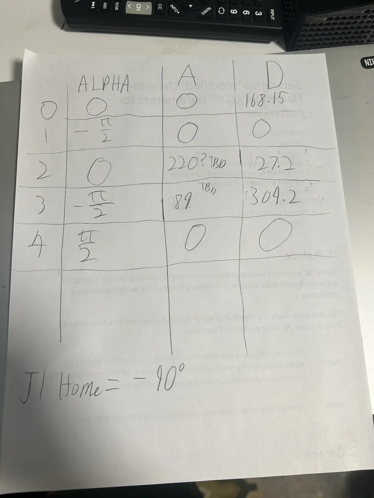
To set it up, I sat down with the printed-out LinuxCNC DH parameters document, which walks you through translating your robot into a set of values called the Denavit–Hartenberg parameters (shortened to DH). I cross-checked everything against my CAD model and filled in the parameters. Those are the values genserkins uses as a reference to calculate the joint angles. The DH convention is universal — every serial robot arm can be described by it — but the actual values are unique to each arm, derived from its specific link lengths and joint geometry.
Each joint is described by four standard numbers: a (link length, how far apart two consecutive joint axes are), α (link twist, the angle between those axes), d (link offset, how far along the axis the next link sits), and θ (the joint angle). For a rotary joint like every joint on my arm, θ is the variable the motor changes, while a, α, and d are fixed by the physical build.
LinuxCNC's genserkins reads these as named values in the [GENSERKINS] section of the INI — A_0, ALPHA_0, D_0, A_1, ALPHA_1, and so on, one set per joint. From them it builds the chain of transforms that defines forward kinematics (joint angles → tool position). The clever part is the reverse: every servo cycle, when I world-jog, genserkins takes the desired tool position and solves that transform chain backwards numerically to find the joint angles that achieve it. That numerical inverse solve, repeated at the servo rate, is exactly the workload the Raspberry Pi 4 couldn't keep up with. It also means a single wrong or missing DH value (I lost an afternoon to one undefined ALPHA term) makes the solver describe an arm that doesn't match reality, and inverse kinematics fails or produces impossible joint angles.
The HAL File
The HAL (Hardware Abstraction Layer) in LinuxCNC is a modular framework that connects software components—like motion control, encoders, and I/O—through configurable signals, pins, and parameters, much like wiring together physical electronic components. It lets you map real or simulated hardware to LinuxCNC's internal logic without changing source code, so you can route signals between drivers, motion controllers, and GUI elements purely through configuration files. In layman's terms, the HAL file is what links everything together. It connects the kinematics joint positions to the motion controller's joint positions.
File to add
Link the HAL config file / generated HTML doc here.
From the HAL file, the motion connects to a custom Python script running on the computer (also generated by Claude). That script communicates with a Raspberry Pi Pico 2W running custom MicroPython firmware. The firmware holds, for each axis: the step and dir pins, the steps per revolution, and whether the axis should be inverted to match the DH model. It is in MicroPython instead of C because I do not understand C at all, while I have a small enough understanding of MicroPython to make little changes myself.
Here is the whole signal chain, from the motion planner down to the motors:
┌─────────────────────────────────────────────────────────────┐
│  Desktop PC (Debian + PREEMPT_RT)                            │
│                                                              │
│   LinuxCNC  ──►  genserkins  ──►  HAL  ──►  pico_hal.py      │
│   (planner)     (kinematics)    (wiring)   (Python bridge)   │
└───────────────────────────────────────────────┬─────────────┘
                                                 │  USB serial
                                                 │  (binary protocol:
                                                 │   5 joint angles + feedback)
                                                 ▼
┌─────────────────────────────────────────────────────────────┐
│  Raspberry Pi Pico 2W (MicroPython firmware)                │
│                                                              │
│   parse packet ──► per-joint PIO state machines ──► STEP/DIR │
└───────────────────────────────────────────────┬─────────────┘
                                                 │  STEP / DIR pins
                                                 ▼
                              Stepper drivers  ──►  Stepper motors
                                                    (the arm joints)
The same joint-pos-commanded value that HAL feeds to pico_hal.py is also tapped off to the VisMach 3D model, so the on-screen arm and the physical arm always show the same commanded pose.
The Motion Pipeline
The script on the computer talks to the firmware on the Pico over a custom binary protocol that carries the absolute commanded joint angles (one float per joint, in degrees). The Pico does the math: it converts each commanded angle into an absolute step target using that joint's steps-per-revolution, then generates the steps needed to reach it. It reports its current position back in the same format so LinuxCNC can close its position loop.
I used a fixed-size binary packet rather than plain text for three reasons: it's compact (a handful of bytes per joint instead of a string of digits), it parses in constant time on the Pico with no slow string-to-float conversion, and the fixed length makes a dropped or misaligned packet trivial to detect — if the bytes don't line up to the expected size with the right start and end markers, the firmware throws the packet away and resyncs on the next one.
To actually generate the step signals, it uses the Pico's built-in PIO (Programmable Input/Output) state machines — one per joint. They run independently of the main processor, so step timing is never disturbed by interrupts or whatever the CPU is doing. Each state machine runs at a fixed clock, but the rate of each burst is set on the fly: every servo cycle the firmware works out the exact velocity LinuxCNC commanded for that joint and feeds the PIO a matching per-step delay. That means the motor turns at precisely the commanded speed in smooth, continuous motion, rather than firing each move as a full-speed burst followed by an idle gap (which is what causes steppers to buzz and vibrate).
A PIO state machine is a tiny dedicated processor inside the Pico that runs its own minimal program separate from the main CPU — just enough instructions to toggle pins with cycle-exact timing. Because it isn't running Python and can't be interrupted by anything else on the chip, the pulses it produces are perfectly evenly spaced. If the main CPU generated the pulses instead, every garbage-collection pause or incoming serial packet would jitter the timing and the motor would stutter.
It communicates over the Pico's regular USB port. That works, but it isn't ideal, and at the time I didn't realize there were better options, there exist Pico 2W variants with built-in Ethernet ports that would enable much higher-speed communication.
The HAL file also exposes a genuinely amazing number of variables, way more than I use. There is per-joint homing status (whether a joint is actively homing, homed, or not), spindle controls (which obviously don't apply to me, I am not putting a large spinning piece of sharp tooling on the end of a fragile printed arm), and a lot more. It is an extremely powerful tool.
VisMach Visualization
The HAL file also initializes a VisMach Python script (Claude generated the first version on its initial run as a little starting summary). VisMach is a software visualization of where the arm is in space.
To build it, I went into Fusion 360 (where I modeled the arm) and exported the ASCII STLs, not the binary STLs. That part is important: binary STLs will not work. Then I took the initial Claude-generated script, imported all the STLs, added them to their respective joint definitions, and added primitives for the base (rather than importing a static model, which I don't know how to do). I applied the correct transformations to each model and linked them with the proper ratio to the HAL file's joint-pos-commanded variable, which is the same variable the Pico motion controller reads from. So the on-screen model and the real arm both follow the same commanded position.
Image / video to add
Add a screenshot or clip of the VisMach model tracking the arm here.
The reason watching the commanded position matters so much comes down to one fact about this arm: there are no encoders. LinuxCNC only ever knows where it told the joints to go, not where they physically are — the Pico reports back the steps it generated, which is the same commanded number, not a real measurement. VisMach shows you that commanded world: the on-screen arm is a perfect render of where the controller believes the arm is.
That makes the on-screen model and the physical arm a built-in comparison. If a motor stalls, skips steps, or a belt slips, the controller never finds out — but the real arm visibly drifts away from the VisMach model. So the visualization isn't just a pretty display; with no encoder feedback, it's the only way to see the gap between the commanded pose and reality and catch when the open-loop assumption has broken down. It also lets me dry-run and verify a move on screen before committing the physical arm to it.
Problems I Hit
The protocol didn't match. The AI-generated code wasn't communicating over USB correctly, there was a small mismatch in the binary protocol between the HAL-side script and the Pico firmware. Lining the two up fixed it.
The two sides disagreed on the packet length. At one point the computer-side script was sending a 23-byte packet (it had an extra byte tacked on the end) while the firmware was still expecting 22 bytes. Because the lengths didn't match, every packet after the first was read starting one byte off, so the float data decoded into garbage. I tracked it down by dumping the raw bytes the Pico was actually receiving and seeing the start marker land in the wrong position. Once both sides agreed on the exact byte layout, it lined up immediately.
chmod +x. I don't use Linux, so I spent about an hour banging my head on the keyboard before realizing you have to run chmod +x on the HAL script to make it executable. Without that you just keep hitting the same "not executable" error over and over.
Line endings. When you bring files from Windows into Linux, the line endings are different. Windows uses CRLF and Linux expects LF, and the parser will choke on the Windows endings and refuse to read the file. You have to convert CRLF to LF first.
The fix is to strip the carriage returns. I ran sed -i 's/\r$//' filename on each file after copying it over (the dos2unix filename utility does the same thing if you have it installed).
Following errors and position feedback. As mentioned above, LinuxCNC requires position feedback or you get a joint following error. The Pico generates the steps and sends back its position, and LinuxCNC checks whether that exceeds the maximum following error defined in the joint setup. If it does, it doesn't cut power, but it blocks itself from setting any new joint positions. Importantly, there are no actual encoders, the Pico just reports the steps it generated and derives the joint position from that. I went this route for two reasons: the Pico does not have enough IO to support real encoders on every joint, and adding them would be an entire extra layer that is way overkill for what I am trying to do.
More info to add
Add the actual following-error message/screenshot, and the max following distance value I settled on.
Download
todo's
Desktop running — photo of the HP Envy at the LinuxCNC desktop (Computer & OS section)
Latency test result — screenshot showing your ~8,000 ns max jitter (Real-Time Kernel section)
INI config file — link or generated HTML doc (INI section)
HAL config file — link or generated HTML doc (HAL section)
Control software repo / firmware — link (HAL section, repo note)
Hand-homing — photo of moving the joints to their zero positions by hand (Homing section) VisMach tracking the arm — screenshot or, better, a clip of the on-screen model moving with the real arm (VisMach section) Following-error message — screenshot of the actual fault, plus fill in the max-following value you settled on (Problems section)