Week 11
Check List
This week's project requirements:- Send a message between two projects
- Document your work on the group work page
- Reflect on what you learned on your individual page
Individual Assignment:
- Design, build and connect wired or wireless node(s) with network or bus addresses and a local input and/or output device(s)
- Document the process
Images/Files:
- Include your original design files
- Properly compress or use a zip folder if needed
- Include hero shots of your results
Group Assignment:
Resources and Helpful Links
- ESP-NOW Wireless Communication Protocol
- ESP-NOW FAQ
- ESPNOW for Beginners
- Device to Device Communication with ESP-NOW
- Image of the XIAO ESP32-C6 Board Pins
Learning Outcomes
- Demonstrate workflows used in network design
- Implement and interpret networking protocols and/or communication protocols
Group Work
My Contribution to the Group Work
-
My Contributions to this week:
- I connected my ESP32S3 with the OV3660 camera module to our group web server for additional connection testing.
- I connected to our groups server using my computer.
- I tested the connection to Dorians board using the on and off buttons on our webpage.
For a more in depth look at my groups week 11 assignment, see my groups Week 11 page.
Introduction
For my final project I have been working on finding an alternative to Home Assistant or a way to get it to work directly using my ESP’s. I was trying to save money and hoping to find a way to make it work. The raspberry pi 5’s, which is what is suggested, are 150 - 200$ and I feel like that is a lot of money for a single component and for one feature, albeit a main feature.
While I was looking into alternatives to using Home Assistant on the Raspberry Pi’s I ended up finding ESP Now. The more I looked into it, the more I realized it would not work for my final project needs, but it was really helpful researching it for Networking week!
Aside from working on my Home Assistant, I also started learning how to use Touch Designer. Touch Designer is a cool node based audio/visual synthesizer. With some cool add-ons you can create some cool interactive hand tracking and face tracking activities. I also found a great Instagram shorts that showed that you can link an Arduino directly to the Touch Designer with the Data Nodes!
So for my networking week I wanted to try and merge the two, if possible!
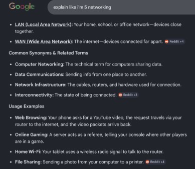
What is Networking?
There was a short time in my life where I worked for a phone/internet company as technical support. I had to take a 3 month training class and learn about networking, communications, and the different tools and methods the company used to support the customers. For weeks leading up to the interview I did a ton of research and during the training I learned a lot. It has been years since then and I still have a general sense of what everything is but I could definitely use a brush up.
I decided to do an Explain Like Im 5 for networking to help pull whatever I can from the back of my brain.
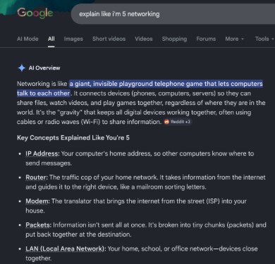
Ahh memories, reading through these terms and meanings I strongly remember getting calls where I had to explain that the internet didn’t just appear and that it was in fact from the black box (modem/router) the company provided and that no internet would happen if they didn't open the box and plug it in.. I bounced so many modems, learned how to check for packet loss, explained that routers won't work as well when stored in a metal box in the garage halfway across the house. Good times.
Setting Up ESP Now
What is ESP Now? ESP Now is a low powered wireless protocol that allows for direct communication between ESP32 devices.
After a lot of research on the ESP-NOW Protocol, I followed this helpful youtube video on setting it up on my computer.
While researching ESP Now, I learned some helpful information. The first bit is that the ESP-NOW protocol only allows pairing for up to 20 devices. According to the Espressif FAQ page, their is a way to get around this, but I should not need more than maybe 3 devices in my final project so I am not worried about hitting this limit.
The second bit of information I learned is that the maximum length of their data is limited to 250 bytes per packet. I am unsure if this will become an issue for me later on, but if it does I will cross that bridge when I get there.
Finally, some of the general benefits of using ESP Now is that it is energy efficient, uses MAC addresses for direct communication, fast communication speeds, and paired devices automatically reconnect after powered down or reset.
Preparing Arduino IDE
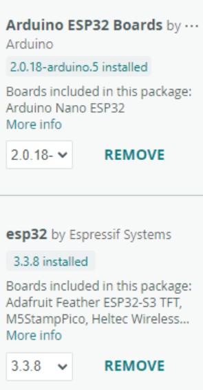
The start of this process is making sure I have the correct boards and libraries in my Arduino IDE. I followed every step in the video even though some I had already completed in previous weeks, like having my boards and libraries. To check that I had the baords set up I had to go to:
Preferences > Additional Board Manager > Click the button on the right that looks like two windows > Add your additional boards to the popup. \
I grabbed the Arduino board manager file from the Esspressif site. Each board manager needs to be on its own line!
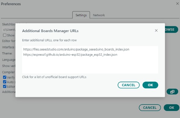
The next step is to ensure I had the board managers installed from the board library. This part I already had done.
The next part of the video talks about plugging in your board and making sure you can write to it. I have already been using the ESP-32s for the past few weeks so I know I can work with them. However, it never hurts to double check so I did run the standard blink code example as suggested in the video.
Setting up the Transmitting and Receiving Boards
In networking there is terminology of Master and Slave for transmitter and receiver. I am not a fan of this antiquated terminology, so I will be using either transmitter and receiver or board numbers like board 1 and board 2.
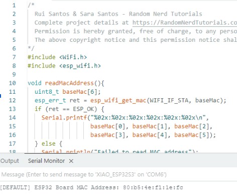
Following the video I started with the ESP Now Master example to set up my transmitter board. Before I could do anything though, I needed to get the MAC address of the boards. At this point, I also realized that the example code in the video was for an ESP-NOW example and the ones I had access to were for broadcasting which I looked up and learned are slightly differnt. It was at this time that I found this site which had example code similar to the one in the video. This site also had a sample code to get the MAC address.
For board 1, I ran the example code in Arduino and got my MAC address quick and easy. But for board 2, not so much, and board 3 (my screen with a built in ESP chip) less so.
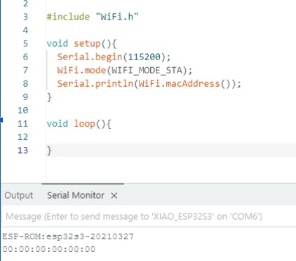
For board two, the MAC address being all 0’s told me something was wrong. So I tried a different mac address code to see if I get the same results. With the new code, which was from the site linked above, I was able to get board 2's MAC address.
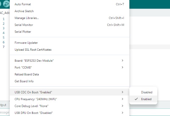
For board 3, since the integrated chip is a different type of ESP compared to the xiaos ive been using, I needed to change some settings in the Tool menu to actually be able to send my code.
-
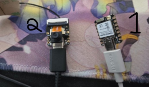
The MAC addressed for my three boards were:
- Xiao ESP32-C6 Board 1: 98:A3:16:85:4D:A8
- Xiao ESP32-S3 Board 2: 80:b5:4e:f1:1e:fc
- ESP32-S3 Board 3: 44:1b:f6:cf:6f:58
Transmitter - Board 1
For board one, I used an ESP32-C6.
Once I had the MAC address for both boards all I needed to do with the example code was put in the receiving boards MAC address. When I ran the code I received an error. I wasn't sure what the error code meant so I asked Chat GPT to exapline it. Chat said that the code I used from the site is for an older version of ESP-NOW. Thankfully, the fix was simply changing one section of the code.
That simple code change, solved the error and it uploaded with ease. After that, there wasn’t much else to do with this board until the second board was set up.
Receiver - Board 2
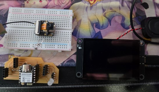
For board two, I used an ESP32-S3 with a camera.
I did the same process as I did for the transmitter board, only using the reciever example code. I checked my board with the blink code to make sure it was working, copied the code from the site, and uploaded the code. The receiving code had the same issue as the transmitter code. With chats help I was able to update the old version of that code to also work.
With that update, the code sent and ran as expected, although it was not very interesting yet.
Board Communication
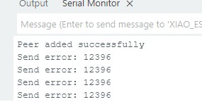
I tried to get my boards to talk by going back to board 1 and watching the monitor. This showed me something was still wrong. With a bit of help from ChatGPT, we discovered that the transmitter and receiver were not on the same channel. Chat had me add in a line to force the channel selection to channel 1. With that change Board 1 was now reading a message of Peer added successfully, but also a send error.
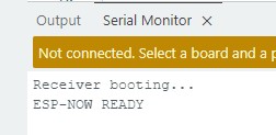
Board 2 though, with the fixes sent out ESP-NOW ready.
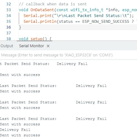
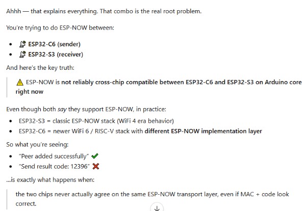
The last step to communicate was figuring out the error I was getting for board 1. I learned a lot about the ESP-NOW error/state code: 12396. I saw it as both a send error and a send result code on board 1 while trying to solve it.
This error has a couple of possible meanings, and I tried to look into each of them as a fix. Some of the reasons you can recieve this error is wrong peer addresses or channels (which we fixed), mismatched WIFI channel between boards, wwrong MAC addresses, packet loss, or poor signal. Basically, its saying thiers some sort of problem communicating, reminds me of the ambiguous Exit status 1 in Arduino. One thing that Chat did suggest though while trying to solve this communication issue is that I try using two of the same types of boards instead of mixed boards.
At Chats suggestions, I swapped out board 2 for a new board that was also a C6. Eventually, I may need to try the other methods it suggested, such as UDP, because thiers a chance I will have this issue later for my final project.
Receiver - Board 4
It was at this point that I skipped tring to use my screen with the built in chip and jumped into just using a second C6. I needed the mac address for this board so I started there.
- Xiao ESP32-C6 Board 1: 98:A3:16:85:4D:A8
- Xiao ESP32-S3 Board 2: 80:b5:4e:f1:1e:fc
- ESP32-S3 Board 3: 44:1b:f6:cf:6f:58
- Xiao ESP32-C6 Board 4: 98:a3:16:85:4d:a8
I updated the MAC address on the sending code and reuploaded to board 1 and got no change in the Monitor. Still, send result code: 12396. This time arround though, my Recieving board (Board 4) put out a new message in the monitor. Along side saying ESP-NOW Ready, it also said Reciever Ready. Board one, the transmitter, is still putting out the 12396 error.
I contnued to work with chat to get board 1 out of the error state. With a quick code edit from Chat, I got the closest yet to connecting them.
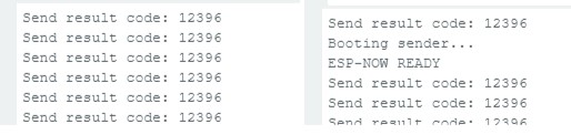
- booting...
- WiFi Channel (receiver): 0
- ESP-NOW READY
My transmitter board showed:
- Sender booting...
- WiFi Channel (sender): 0
- ESP-NOW READY
- Send result: 12396
My Receiving board now showed:
Chat told me this is a good sign, and should be an easy fix because were actually attempting to send out but we havent established an actual channel yet, hence the 0. I tried to update with the fix chat made me, and my computer Blue Screened during the upload process. Yay! Sometimes you just want to give up, and this feels like one of those times…
Im grateful that everything I had worked on up this point was either saved manually or on a google doc which auto save.
I took a mental break and strepped away from my computer, but I am so glade I didnt give up completly. After letting my computer reset, and letting myself reset as well, I tried one last time with the updated code from Chat. And I was finally successfully talking between the two boards.

Hallelujah!
Now to make it do something.
Setting Up Touch Designer with Arduino
Since I learned about this program while scrolling through Social Media about 3 weeks ago I have been really interested in learning more about it and learning how to use it. I have followed a few tutorials now to learn how to make particles interact with a mouse, a blob that interacts with sound, and a mouse reactive theremin-like thing that gives off an awful high pitched noise.
It has been a lot of fun to learn this new program!
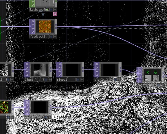
Since I learned that you could bring in Data read outs from Arduino I really wanted to test this out. I followed this video by pausing every few seconds to screenshot the nodes I needed to build to create my interactive blob with the Data input nodes. There isn't much to see or do without the Data inputs so for now it’s just a pink sphere. However, once the data inputs come in from the ultrasonic sensor it will start to change and modify its shape from the noise node reacting to how far or close you are to the sensor!
Using an Ultrasonic sensor:
I tried to use an ultrasonic sensor because I saw a short tutorial that walks through the nodes needed to connect ultrasonic sensor data to Touch Designer.
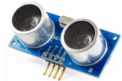
After a lot of trouble shooting, google searching, and a quick (but not useful) chat with Chat GPT, I realized the Ultrasonic sensor needed 5 volts and it would not work from the ESP’s.
For now, I will put this portion of the project aside and set up my ESP Network to do something a bit simpler. 🙁 I will come back to this project though, as I have learned that this would be a good project to try again during week 16!
Making my Network do Something Simpler
I am disappointed I couldn't make my ultra sonic sensor work, but it probably is for the best to start simple first anyways. It was a struggle enough to get my ESP’s to just connect, let alone try and do something.
I set up my ESP Now server and connected a tiltball switch in pin 6 and an LED as a visual that its working in pin 7 On board 1. On board 4 their is an LED in pin 7.
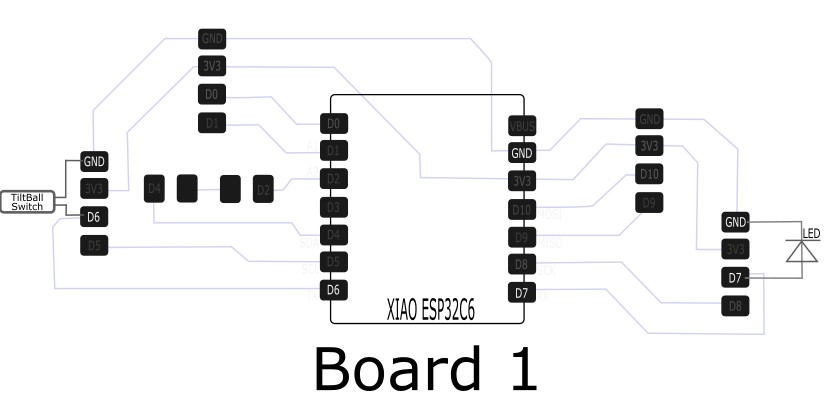
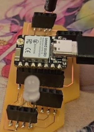
The goal is to have the LED on board 4 light up when the tiltball switch on board 1 is tilted. I had chat help me integrate a basic tiltball switch code into my ESP NOW sender/reciever code. It felt like it would be more intimidating then it really was, which was just adding in my variables and putting my titlball switch code in the void loop.
You can find a copy of the code used for the tiltball switch in my Week 11 files below labeled: Transmitter_TiltBall
Currently, the tiltball switch on board 1 successfully turns off the led when tilted. However, the receiving board is not turning the led on or off with a command, the led is just always on.
The first thing I needed to do was make sure the tilt ball switch was actually changing states from 0 and 1. This is how we use the tiltball switch to send the command. When the tiltball switch is turned, the state changes to a 1. When that state is read, it then should send a signal to Board 4 to turn on its LED.
By checking that the states are changing, I am able to at least know the switch is not the issue. Next I checked the receiver to see if it was properly receiving the 0 and 1 commands from the switch.
At this point, I lost communication between the boards. I backtracked to my last working communication code to get them communicating again. After going back to a known good state, I slowly built the code back into each one. Since I was going back to this known starting point, I also took the time to swap the HIGH and LOW values for the tiltball switch. I noticed when I ran it earlier, the led was on and turned off with the tilt and not the other way around.
It took a bit of tweaking and some research online, but I did finally get my boards to communicate as I planned! When I tilt board 1, the LED turns on on board one. Board 1 also sends a signal to board 4, and tells board 4 to turn on it's LED!
Success!
Week 11 Files
In my repo is a zip folder containing files for my week 11.
What files are inside my Folder:
ESP_Now Broadcast_Master Example Code
ESP_Now Broadcast_Slave Example Code
MAC Address Code Version 1
MAC Address Code Version 2
Reciever Code Version 1
Final Reciever Code
Transmitter Code
Transmitter Code with the Tiltball Switch
Download My Week 11 Project Files Zip Folder