7. Computer-Controlled Machining
This week I designed and fabricated a flat-pack plywood stool (~450 mm tall) on the lab's large-format CNC router. The individual assignment has two parts: demonstrate 2D design development for CNC milling production, and describe the workflows and operations for large-format CNC machining. My project uses press-fit cross-lap joints — three unique parts, no screws or glue.
Assignment checklist
- Linked to the group assignment page
- Demonstrated 2D design development for CNC milling production
- Described workflows and operations for large-format CNC machining
- Reflected on lab safety training and group characterization results
- Documented problems encountered and how I fixed them
Project overview
The stool consists of a round seat and two leg panels that cross-lap together. All dimensions are driven by user parameters in Fusion 360 so I could adjust material thickness and joint clearance after the group characterization tests without redrawing geometry.
| Dimension | Value |
|---|---|
| Seat diameter | 360 mm |
| Overall stool height | 450 mm |
Material thickness (wood_thick) | 18.288 mm (measured on sheet: 18.3 mm) |
| Slot width (with clearance) | wood_thick + clearance |
| Cross-lap slot depth | Half of leg height |
| Sheet layout | Nested on HDF half-sheet (1220 × 610 mm) |
Group assignment
Before cutting final parts, our group completed CNC safety training and characterised the Tiancheng Xinli 3STX-1325A router (1300 × 2500 mm working area) on 18 mm HDF. We tested runout, alignment, fixturing, speeds, feeds, materials, and toolpaths, and recorded recommended parameters on the group page:
Week 7 Group Assignment — Chaihuo Fab Lab
Key numbers I applied directly to my individual project:
| Parameter | Group result | How I used it |
|---|---|---|
| Measured board thickness | 18.3 mm (nominal 18 mm) | Set wood_thick from caliper reading, not the label |
| Kerf | ≈ 0.4 mm | Added clearance to receiving slots in the 2D layout |
| Press-fit slot offset | −0.4 mm per side | Tuned slot width after a scrap test cut |
| Dog-bone radius | Bit radius (3 mm for 6 mm tool) | Added at all internal corners in the 2D sketch |
| Recommended feeds | 24 000 rpm / 2000 mm/min / 6 mm per pass | Used as starting values in MasterCAM |
| Tabs | 3 mm tall × 5 mm wide at corners | Kept parts attached until the outer contour finished |
Personal reflections
CNC machining felt very different from laser cutting (Week 3). On the laser, kerf is small and a 0.1 mm tolerance is often enough; on the router, a 6 mm end mill removes much more material, the board can flex over a 2.4 m bed, and Z-zero must be set to the actual top surface — not the machine bed.
The group test that changed my design approach most was measuring real board thickness. Our HDF sheet read 18.3 mm, not 18.0 mm. Designing slots from the nominal size would have made assembly impossible. Parametric parameters let me update one value and regenerate both the 3D model and the 2D nesting layout.
Safety training with instructor Matthew reinforced habits I kept throughout the job: dust collector on before start, no loose clothing near the spindle, board fully screwed down before the first pass, and never leaving the machine unattended.
2D design development for CNC milling production
I followed a parametric flat-pack workflow in Fusion 360 — similar to the approach in Taylor Stein's flat-pack furniture tutorial. The goal was a robust 3D model that exports clean 2D profiles for MasterCAM, with joint clearance and dog-bone fillets built into the design rather than patched after the first cut.
Design concept
I chose a round-top stool with two crossed leg panels. Each leg has a slot from opposite ends so the panels interlock; the seat drops over the crossed legs through matching slots. Decorative arch cutouts on the legs reduce weight and give the piece a lighter look.
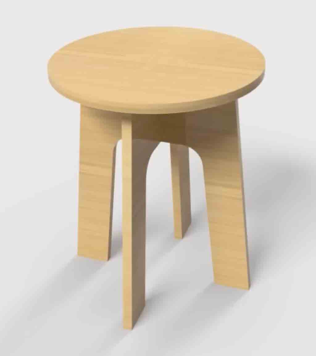
Early concept render — round seat with two crossed leg panels.
Step 1 — Set up user parameters
I created user parameters before sketching so every dimension could update from a single table:
| Parameter | Expression | Purpose |
|---|---|---|
Seat_diameter | 360 mm | Round seat diameter |
wood_thick | 18.288 mm | Sheet thickness (linked to extrude depth) |
clearance | 0.2 mm | Joint clearance (tuned after group kerf tests) |
stool_height | 450 mm | Overall stool height |
tool_diam | 6 mm | End-mill diameter for dog-bone fillets |
slot_width | wood_thick + clearance | Cross-lap slot width |
slot_depth | (stool_height - wood_thick) / 2 | Half-lap depth |
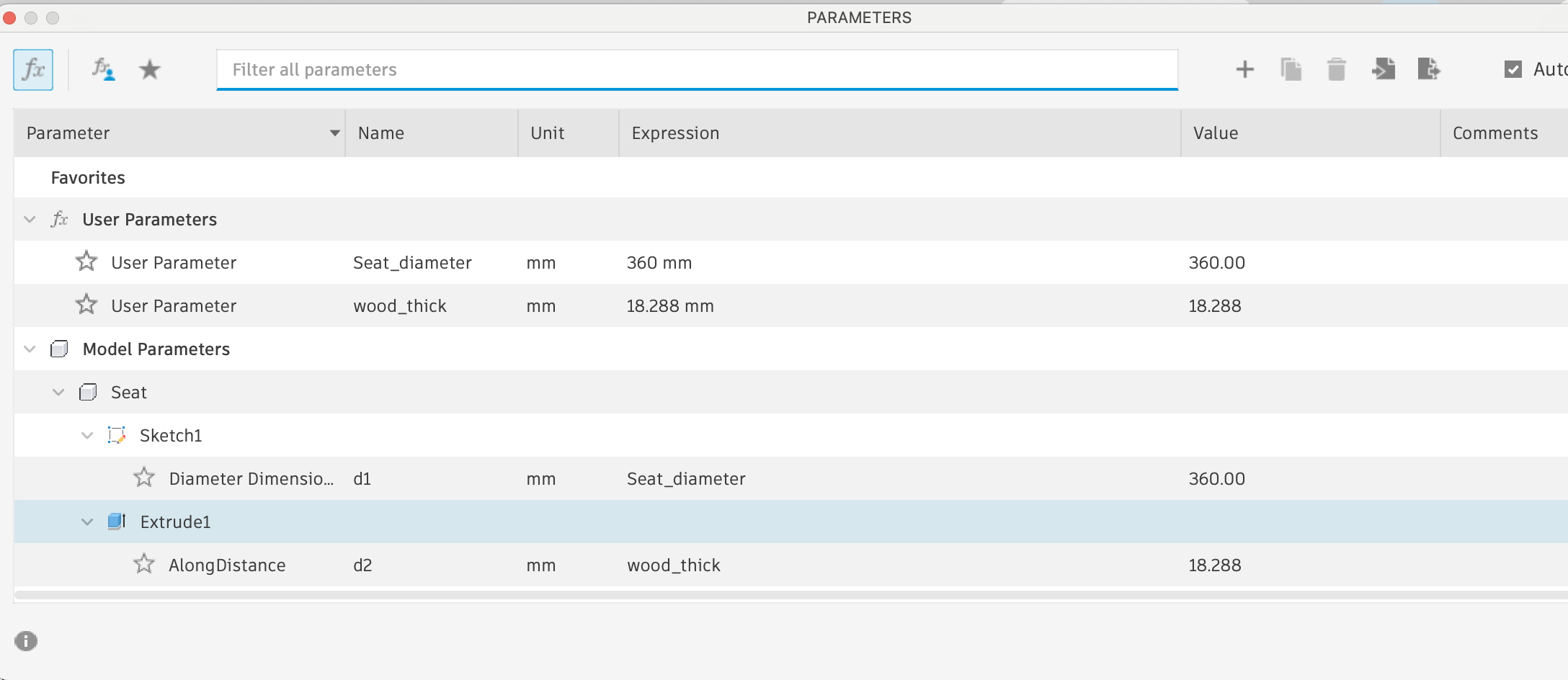
User parameters Seat_diameter and wood_thick drive the seat sketch and extrude —
changing one value updates the whole model.
Step 2 — Model each part in its own component
-
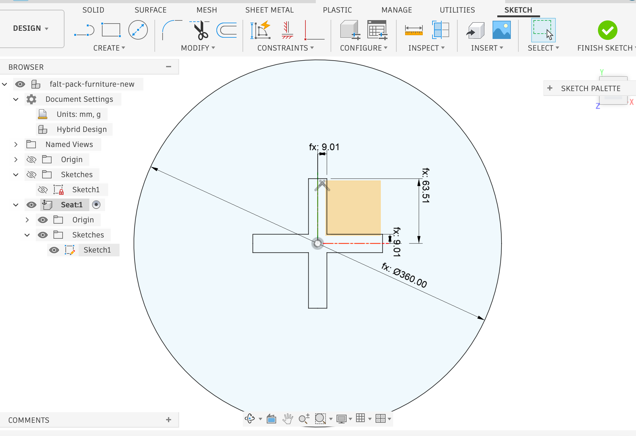
Seat component — Sketch a circle (
Seat_diameter) on the bottom plane, extrude towood_thick.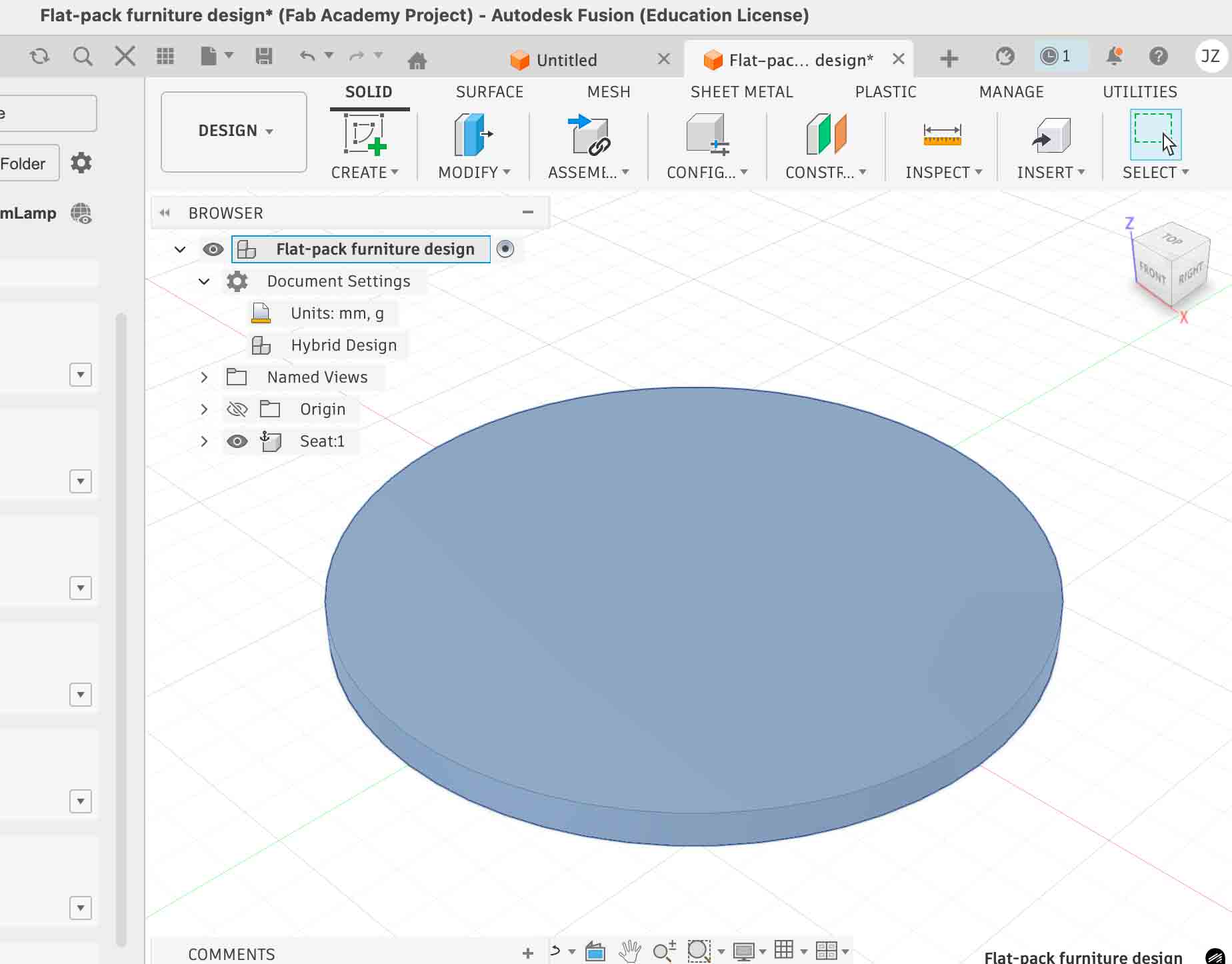
Seat component: circular sketch extruded to
wood_thick. -
Leg component — Create a new component, activate it, and sketch the leg profile on a
side plane. Use Project to reference the seat edge so slot positions stay linked to the
seat diameter.
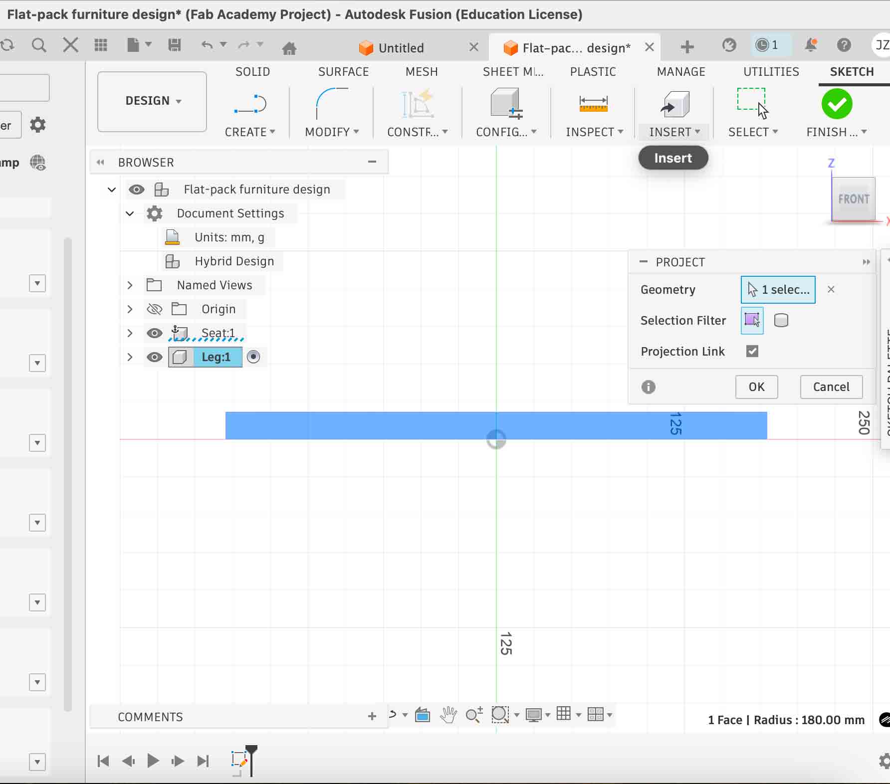
Projecting seat geometry into the leg sketch with Projection Link enabled — if the seat size changes, the leg slots update automatically.
-
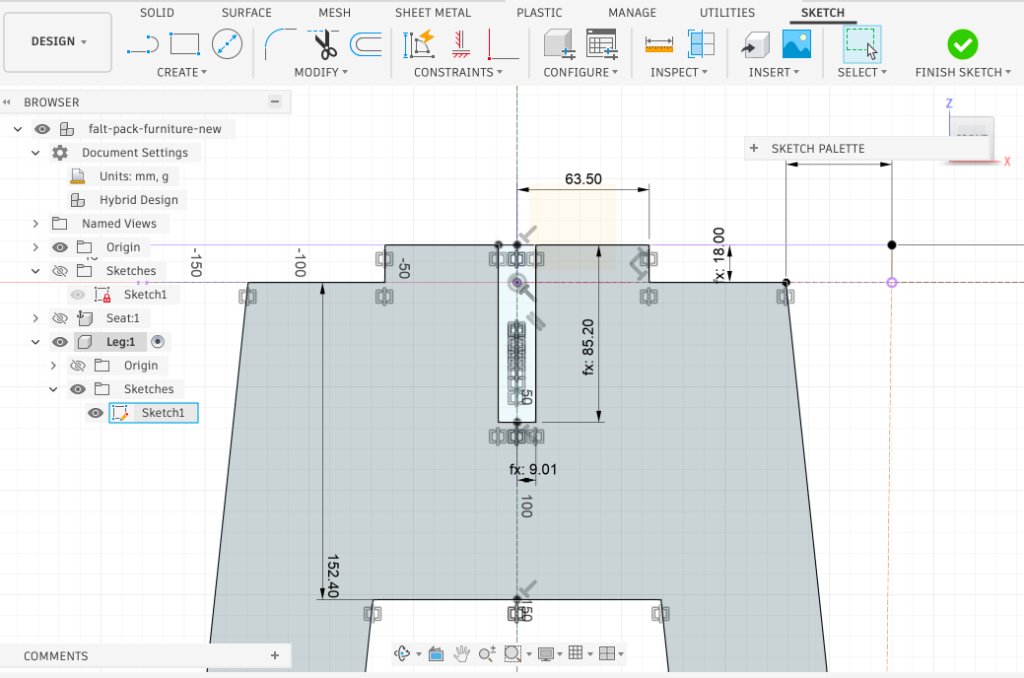
Cross-lap slots — Sketch slot rectangles dimensioned with
slot_widthandslot_depth. Mirror about the centre line for symmetry.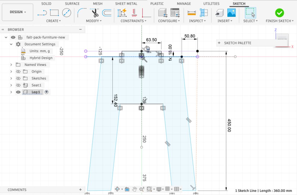
-
Second leg (Paste New) — Copy the leg component with Paste New (not
Paste) so the two legs are independent instances. Rotate 90° and move the slot to the opposite end so
the panels interlock top-to-bottom.
-
Seat slots — Sketch two perpendicular slots through the seat centre, each dimensioned with
slot_width, so the seat drops onto the crossed legs.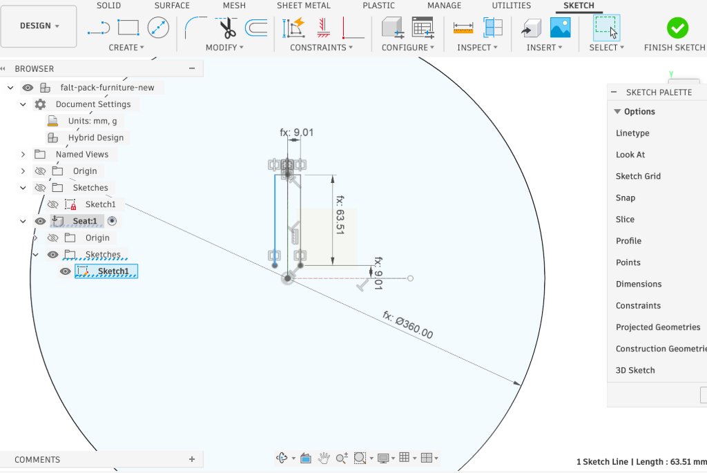
-
Dog-bone fillets — At every internal 90° corner, sketch a dog-bone relief: 45°
construction line, circle diameter =
tool_diam, centre offset =tool_diam / 2from the corner. A round bit cannot reach a true square inside corner; without this relief, the mating tab will not seat fully.
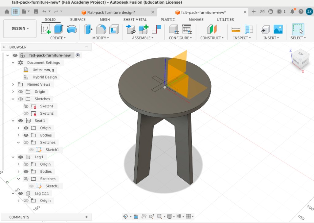
Step 3 — Assemble and verify in 3D
- Joint the two leg panels at 90° and confirm the cross-lap slots align.
- Place the seat on top and run Inspect → Interference to check for clashes.
- Change
wood_thickto 18.3 mm (measured value) and confirm all joints still fit.
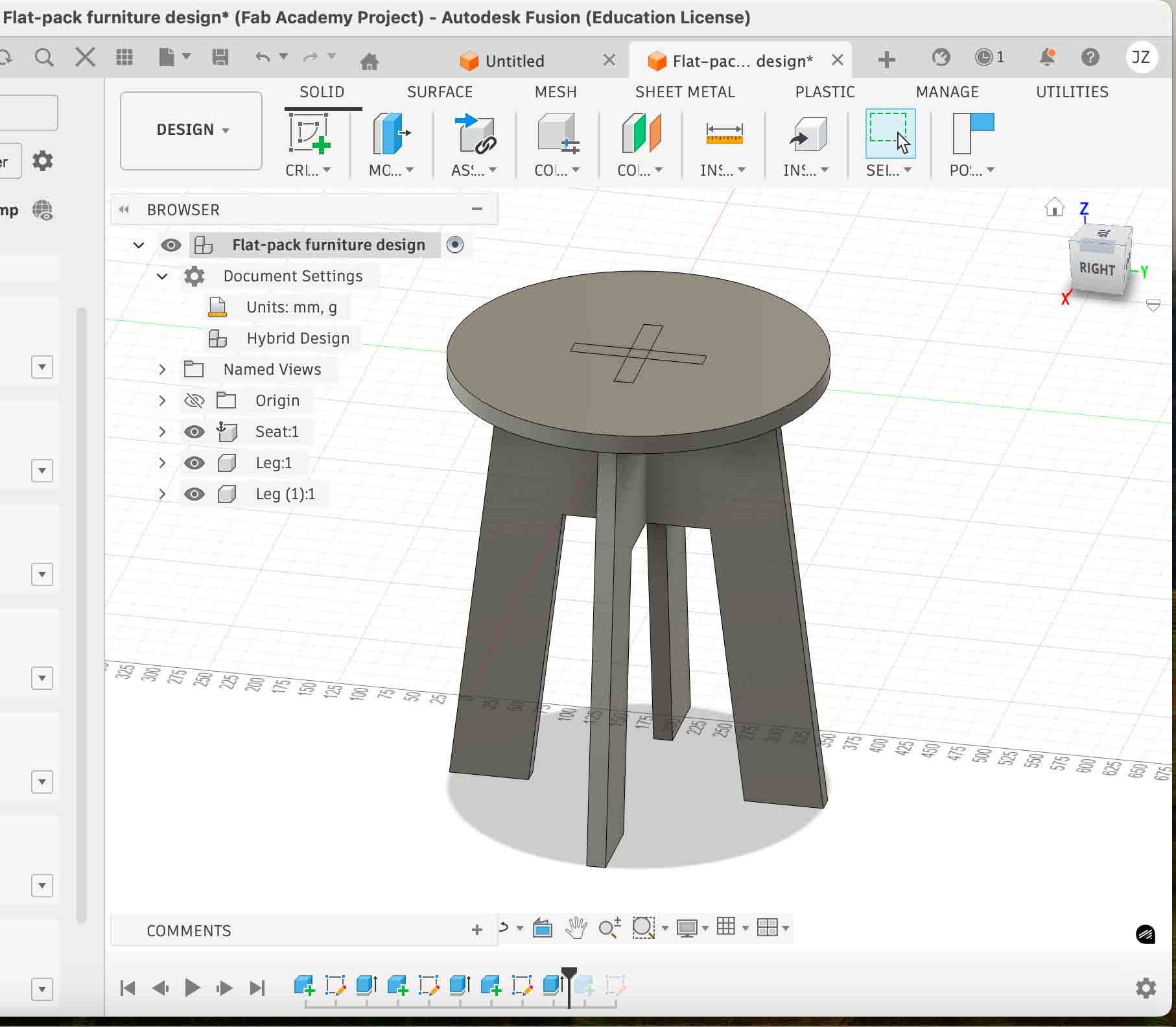
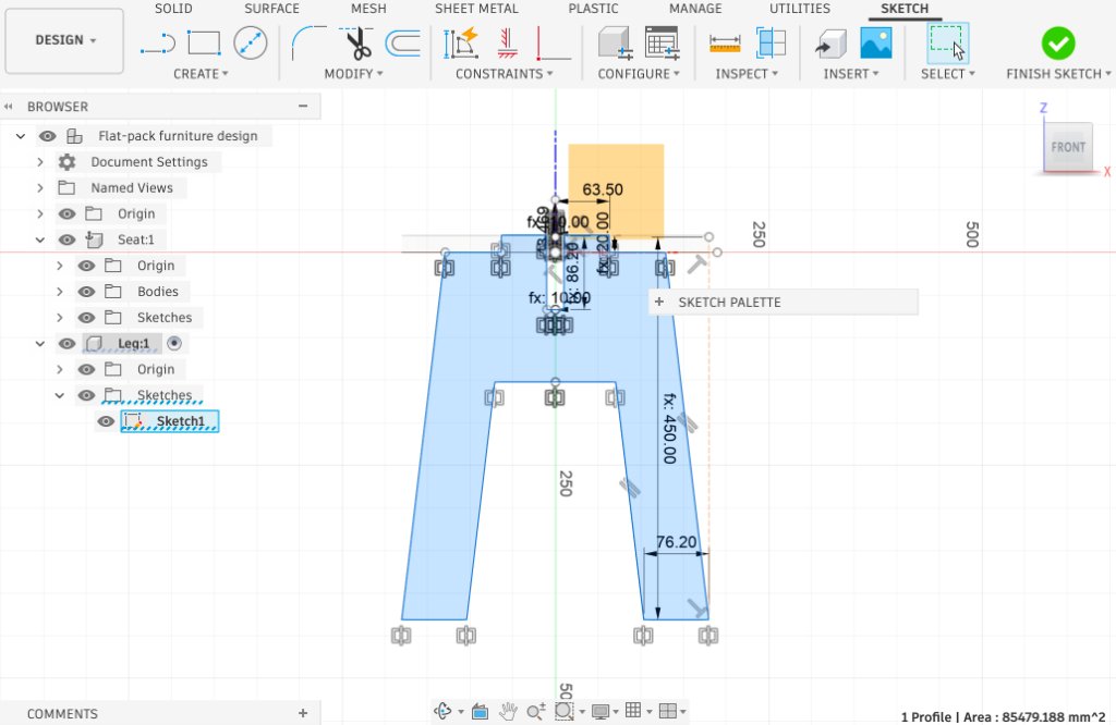
Final parametric assembly — Seat, Leg, and Leg (1) components ready for 2D export.
Step 4 — Export the 2D nesting layout
I exported the flat profiles from Fusion 360, arranged them for cutting, and prepared the file for MasterCAM:
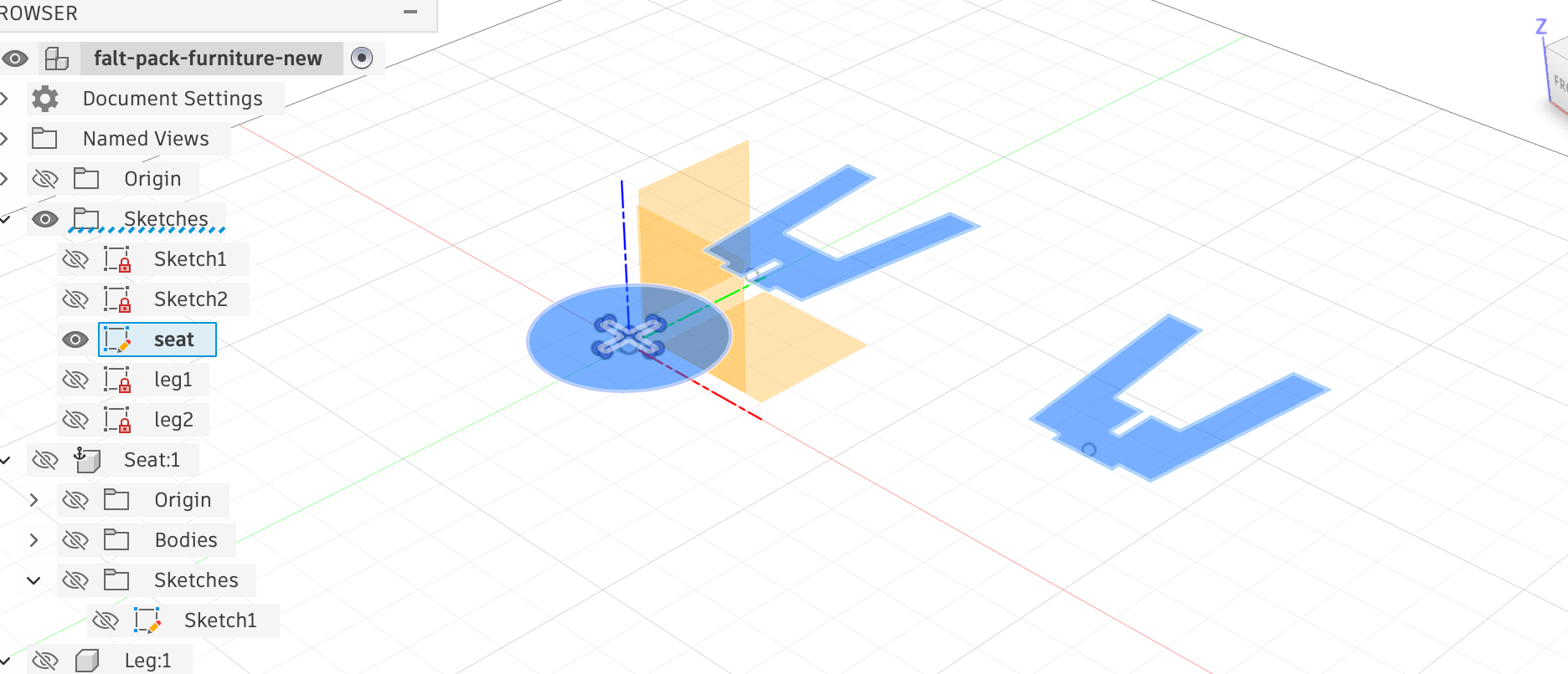
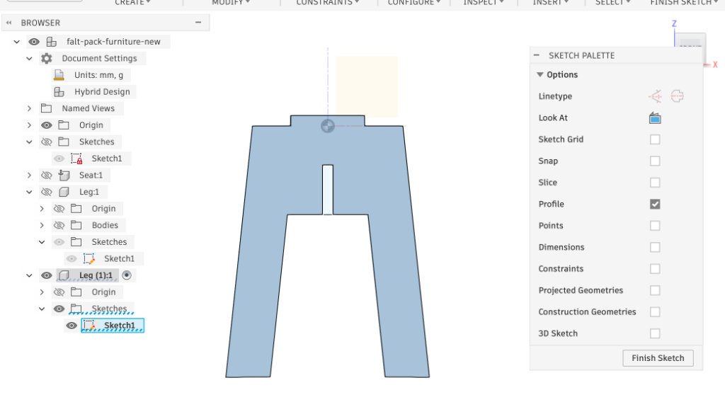
Flat profiles projected and arranged in Fusion 360 before export.
- Create a CuttingLayout component with a sketch on the XY plane.
- Project each part's outer profile, slot, and dog-bone geometry into one sketch.
- Arrange all parts within 1220 × 610 mm with ≥ 10 mm spacing from edges and between parts.
- Export the sketch as a
.dxffile. -
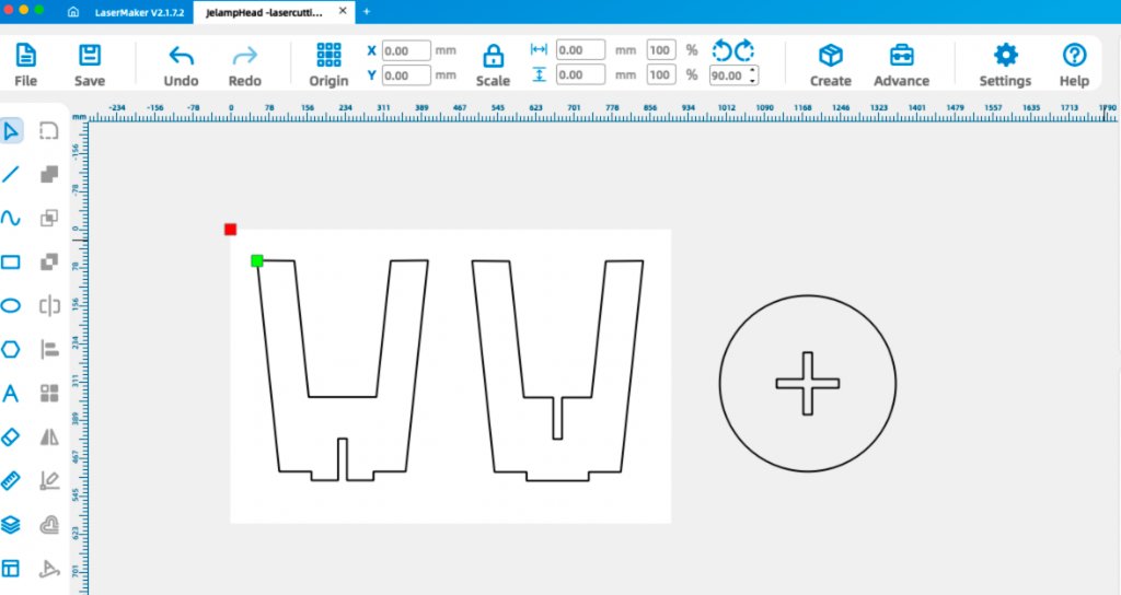
Import the DXF into LaserMaker to verify nesting and part spacing, then prepare the
layout for the CNC workflow.
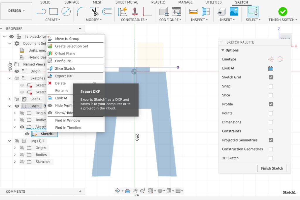
- Import the final layout into MasterCAM X6 for toolpath generation and G-code posting.
The 2D layout is the production file — MasterCAM reads these profiles, assigns toolpaths, and posts G-code for the machine controller. Designing dog-bones and clearance in the sketch (not just in CAM) keeps the parametric model and the cut file in sync.
Workflows and operations for large-format CNC machining
The Chaihuo CNC router is a Tiancheng Xinli 3STX-1325A with a 1300 × 2500 mm bed, 3 kW water-cooled spindle (0–24 000 rpm), and G-code controller. Below is the full workflow I followed from CAM setup through assembly.
Safety training
| Topic | Rule |
|---|---|
| Personal protection | Safety glasses, hearing protection, closed-toe shoes; no gloves or loose clothing near the spindle |
| Emergency stop | Know E-stop and main power disconnect location before starting |
| Dust collection | Turn on extraction before every job — fine wood dust is a health and fire hazard |
| Fixturing | Board must be fully secured with screws into the sacrificial bed; a loose sheet is a safety hazard |
| Supervision | Never leave the machine running unattended; stay within reach of the E-stop |
| Tool handling | Inspect the bit for chipping or wobble before running; never touch the cutter immediately after a job |
Material preparation
- Selected an 18 mm HDF sheet (1220 × 2440 mm) and cut it to half-sheet (1220 × 610 mm).
- Inspected for warping, delamination, or surface defects.
- Measured actual thickness with calipers: 18.3 mm — updated
wood_thickin Fusion 360 and re-exported the DXF.
CAM setup — Mastercam Mill X6
I designed and built an interlocking round stool from 18 mm MDF — two
cross-lapping leg panels and one circular seat, friction-fit with no glue or fasteners. All three parts were
nested on one sheet. CAM was done in Mastercam Mill X6 (JENNYCNCAPR21-FIXED.MCX-6),
posted as JENNYCNC.nc (~16 500 lines) for the Tiancheng Xinli controller.
Steps 1–3 — Geometry, contour toolpath, chain selection
Closed 2D profiles (polylines and arcs) define the leg outlines, cross-lap slots, and circular seat. I used Toolpath → Contour (外形铣削) and selected closed chains — outside for part outlines, inside for slots. Slots were cut first to keep the sheet rigid; outer profiles last with holding tabs.
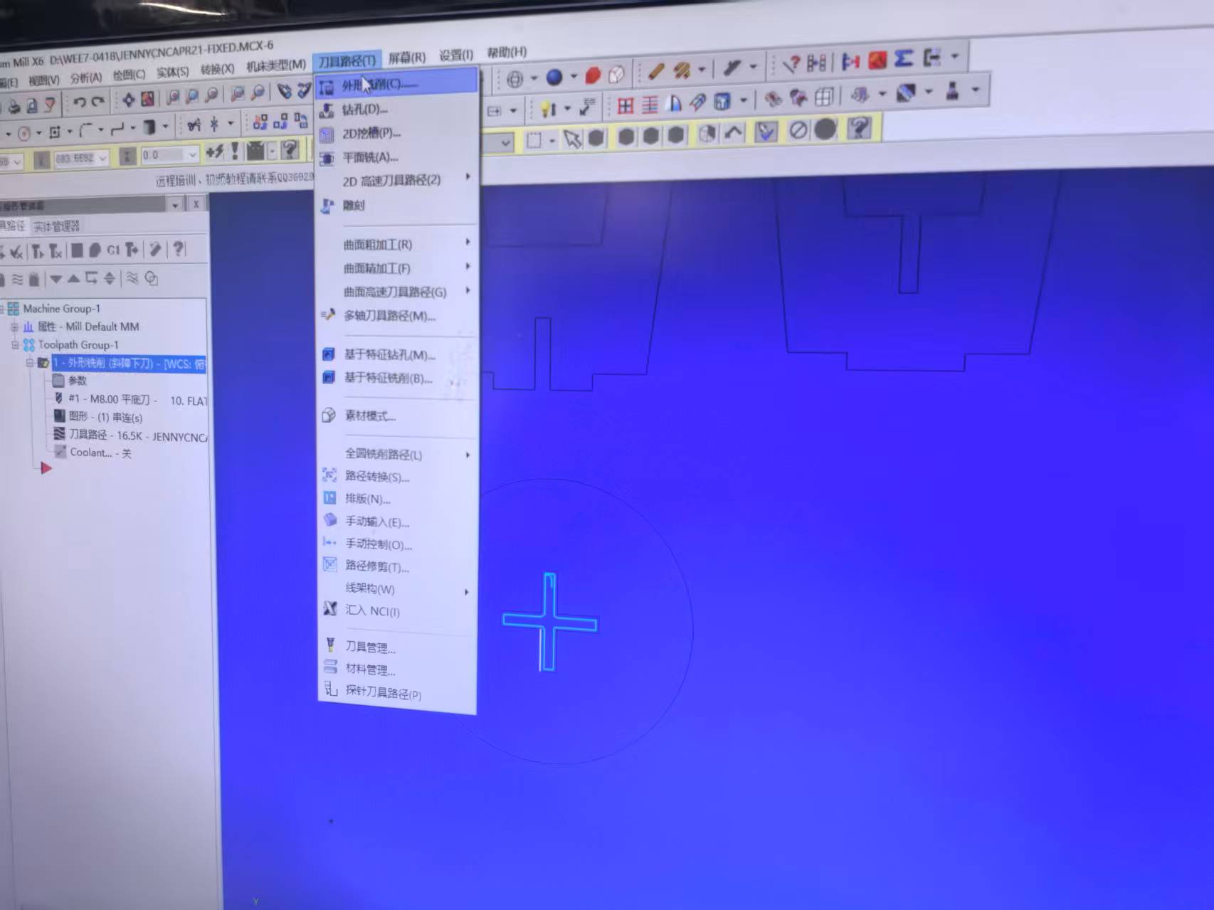
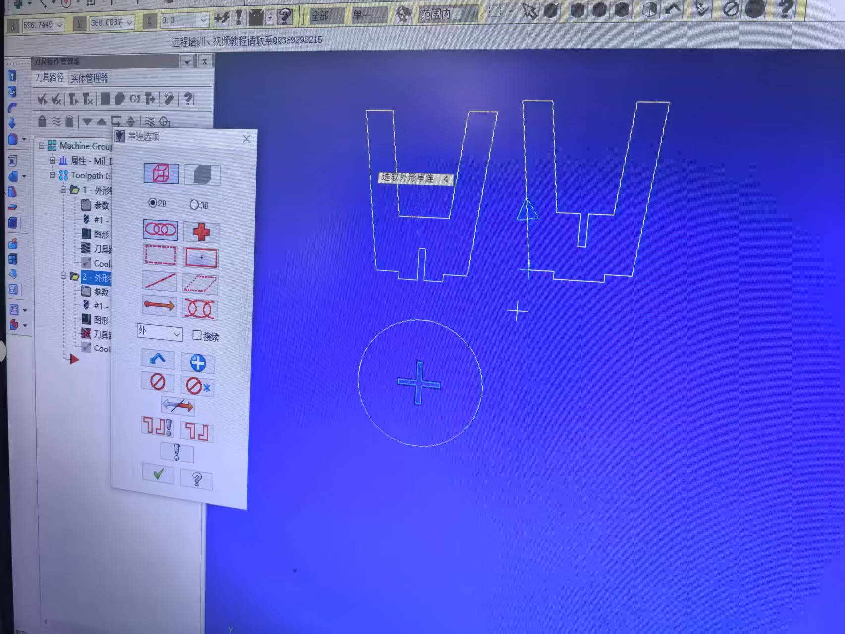
Mastercam setup: 2D geometry, contour toolpath type, and chain selection.
Steps 4–6 — Tool, cut parameters, and linking heights
| Parameter | Value | Notes |
|---|---|---|
| End mill | 8 mm flat end mill | 2-flute; fits slot width, efficient in MDF |
| Spindle speed | 15 000 rpm | Coolant / dust collection ON |
| Feed rate (XY) | 5000 mm/min | FPT ≈ 0.083 mm (conservative for MDF) |
| Plunge rate (Z) | 500 mm/min | Ramp entry 3.0 mm depth / distance |
| Compensation | Computer, left | Climb milling; outside / inside per feature |
| Wall stock to leave | −0.2 mm | Slight overcut for snug friction fit |
| Clearance / retract | 50 / 25 mm | Feed plane 3 mm above stock |
| Final cut depth | −18.2 mm | Through 18 mm MDF + 0.2 mm into spoilboard |
| Tabs | 3 mm × 5 mm at corners | Non-joint areas only |
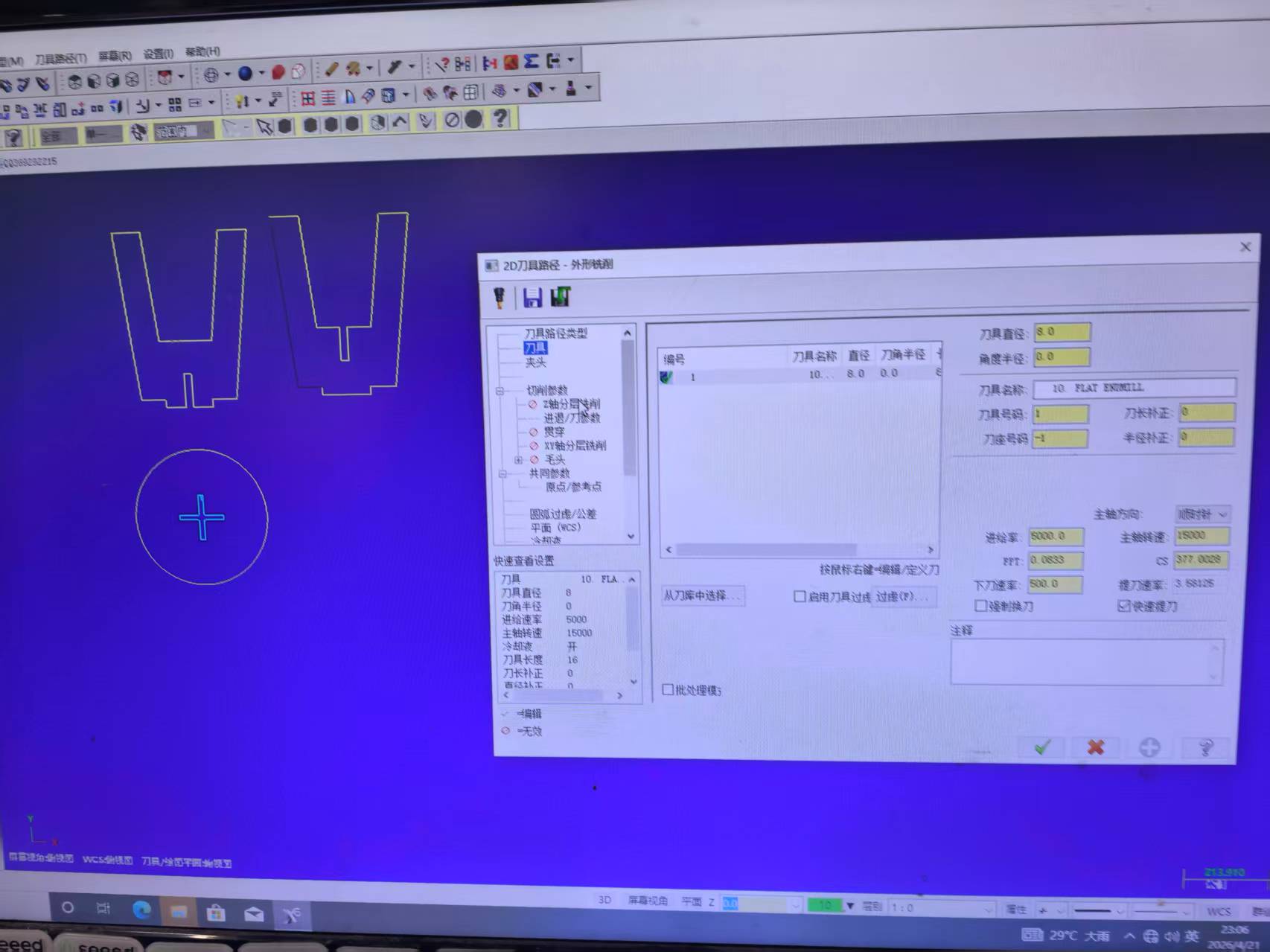
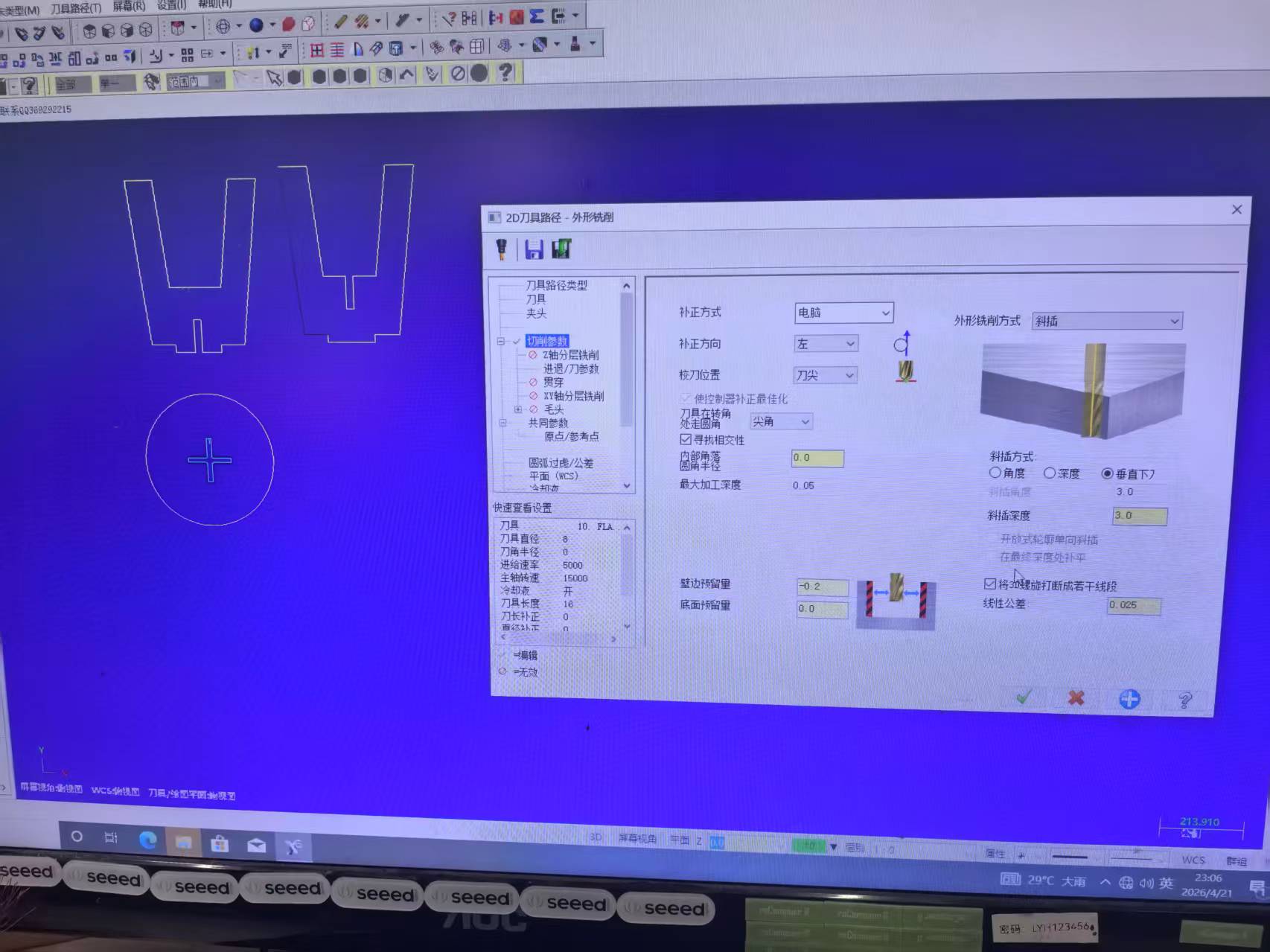
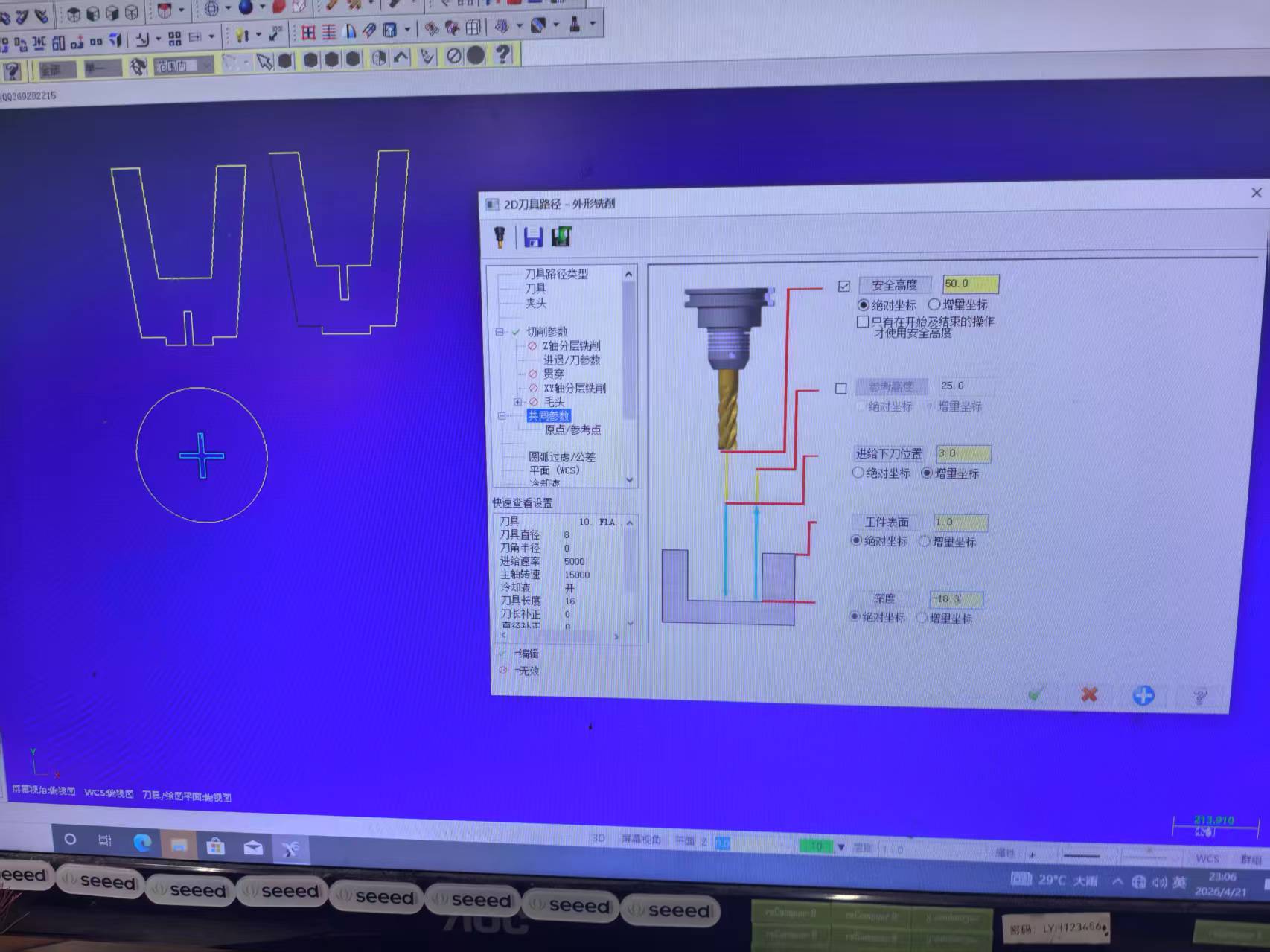
Tool, cut parameters (ramp entry, −0.2 mm wall stock), and linking heights.
Steps 7–8 — Preview and post-process
I verified the generated toolpath — cyan tool-centre path offset ~4 mm outside geometry, yellow rapids, and
ramp lead-ins — then post-processed to G-code (G21 metric, G90 absolute). Sample header:
T1 M06, S15000 M03, G43 H01 Z50.0, multi-pass depths to −18.2 mm.
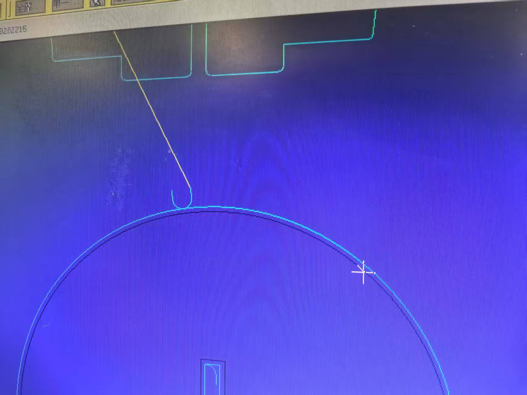
Toolpath preview: geometry (dark), tool centre path (cyan), rapid moves (yellow).
Machine setup, cutting, and finish
- Secured the MDF sheet to the sacrificial bed; set X/Y zero at front-left corner and Z zero on the board top surface.
- Loaded
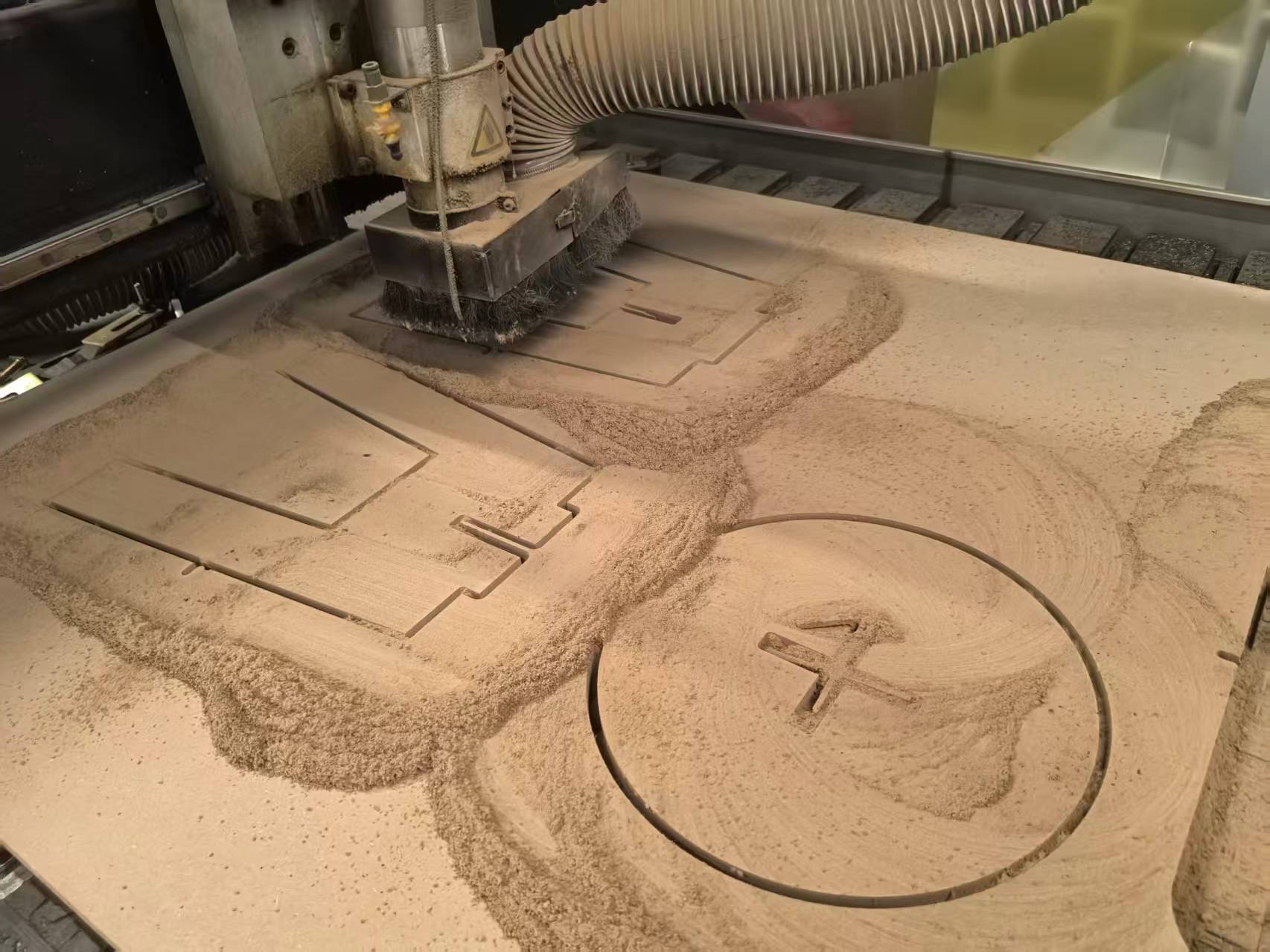
JENNYCNC.ncvia USB; ran dust collection and spindle at 15 000 rpm. - Executed pocket/contour operations (~3 mm per pass × 6 passes). Total time: ~15–20 minutes.
- After the job: vacuumed, broke tabs, sanded edges with 120-grit paper.
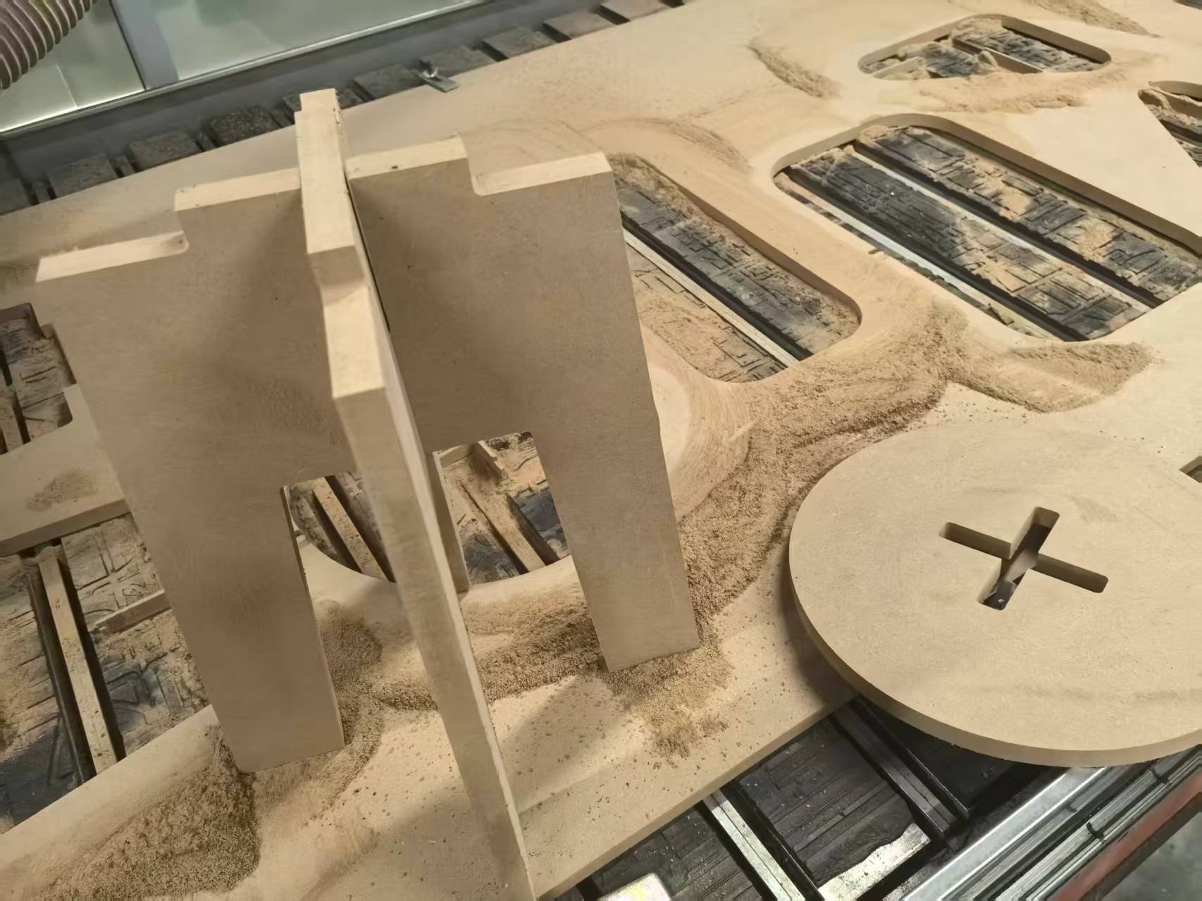
CNC cutting in progress and parts after tab removal.
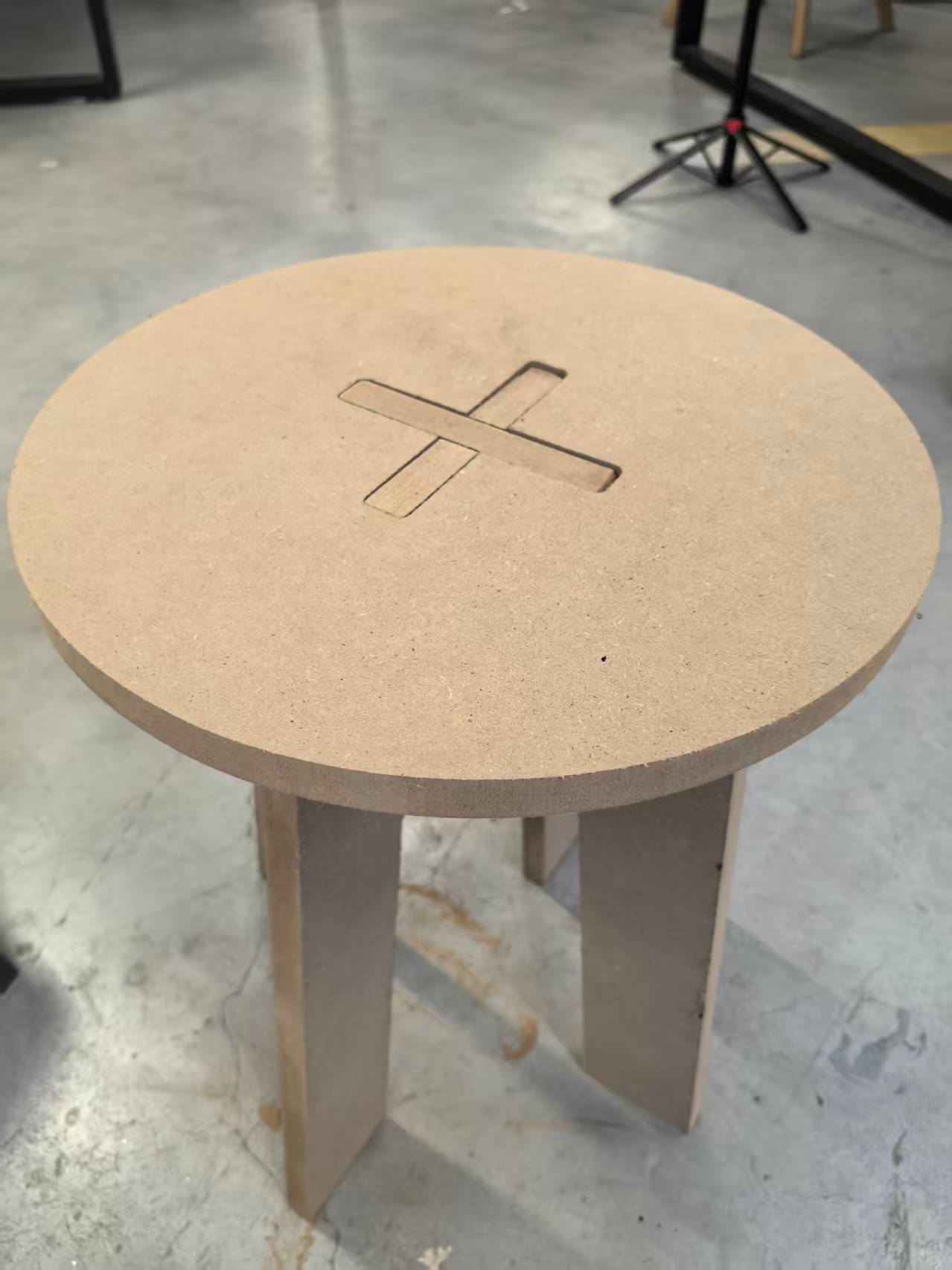
Assembly
- Cross-lap the legs — Slide Leg A (slot from top) and Leg B (slot from bottom) together at 90° to form an X-shaped base.
- Attach the seat — Align the cross-shaped slot with the leg tabs and press down; friction fit holds everything — no glue or screws.
- Load test — All four feet touched evenly; the stool held ~70 kg without wobble.
Problems and how I fixed them
A scrap test cut with slot_width = wood_thick (no clearance) produced a joint that could not
be assembled without excessive force.
Added a clearance parameter (0.2 mm) so slot_width = wood_thick + clearance.
Because the model is parametric, one change updated every slot in both the 3D assembly and the 2D layout.
Without dog-bone reliefs, square inside corners on the seat slots prevented the leg tabs from seating fully — the round bit cannot cut a true 90° internal corner.
Added dog-bone fillets at every internal corner, radius = tool_diam / 2 (3 mm for the 6 mm
bit), following the group assignment recommendation. Re-exported the DXF and re-cut.
On the first full sheet, some areas did not cut fully through — the board was slightly warped and Z-zero was set at one corner only.
Re-zeroed Z at the board centre, increased final cut depth to −18.5 mm (0.2 mm into the sacrificial board), and confirmed the sheet was screwed flat before the second run.
Reflection and key takeaways
- Measure, don't assume. Our HDF was 18.3 mm, not 18.0 mm. Joint design must start from caliper readings.
- Parametric design pays off twice — once during iteration in Fusion 360, and again when adjusting clearance after the group kerf tests.
- Design for the tool. Dog-bone fillets, kerf compensation, and cut order (inside before outside) belong in the design file, not as afterthoughts in CAM.
- Test before committing material. A single scrap joint test saved a full sheet of HDF.
- Large-format CNC demands respect. Fixturing, dust extraction, and staying at the E-stop are as important as feeds and speeds.