Week 10: Output Devices
Assignments
Group assignment: Measure the power consumption of an output device. Document your work on the group work page and reflect on your individual page what you learned.
Individual assignment: Add an output device to a microcontroller board you’ve designed and program it to do something.
Group Work Assignment Reflection
In the group assignment, we measured the power consumption of the SG90 servo motor under different operating conditions to understand its energy demand.
Power consumption measurement: A digital multimeter was placed in series with the servo’s power supply (5 V). The servo was programmed to sweep continuously. The multimeter showed a current draw of 0.31 A when the servo was moving and 0.02 A when idle. Using the formula P = V × I, the power consumption during motion was:
P = 5 V × 0.31 A = 1.55 W
What I learned: The power consumption of a servo depends heavily on the load and speed. Even a small servo can draw several hundred milliamps when moving, which is too much for the microcontroller’s 3.3 V regulator. Therefore, an external power supply must be used for the servo. I also learned to use a multimeter to measure current and to distinguish between idle and active power states.
Individual Assignments
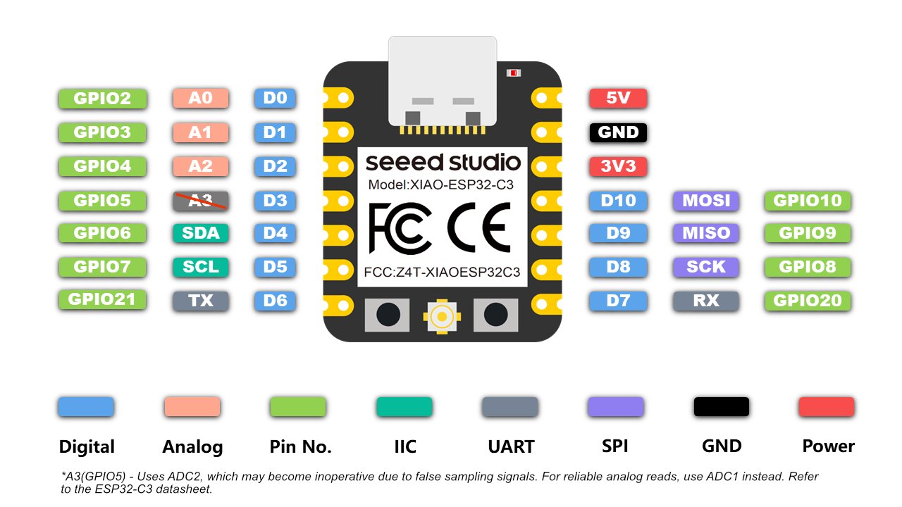
Board design and fabrication (Week 8) — This assignment builds on the custom PCB I designed in Week 8. My board is built around the Seeed Studio XIAO ESP32-C3. You can find the original design files, schematic, and fabrication steps on my Week 8 assignment page.
What is a servo motor?
A servo motor (servo) is a small actuator with a built-in feedback system. Unlike a DC motor that spins continuously, a servo receives a PWM signal and moves its output shaft to a specific angle, then holds that position against light load. Inside the plastic case are a motor, gearbox, potentiometer, and control board — the potentiometer reports the current angle so the controller can correct error.
Most hobby servos have three wires: signal (PWM from the microcontroller), VCC (typically 5 V), and GND. The SG90 I used in this assignment is a common micro servo rated for about 180° of rotation.

Left: SG90 micro servo (same type used in Week 4 and this assignment). Right: animation from my Week 4 bridge demo showing how a positional servo moves to an angle and holds it.
180° vs 360° servos
| Type | How it moves | Typical use | This assignment |
|---|---|---|---|
| 180° (positional) servo | servo.write(angle) sets a position from 0° to 180°; the shaft stops and holds at that angle. |
Robot joints, flaps, gates, camera pan/tilt — anywhere you need a defined angle. | SG90 — my code sweeps 0° → 90° → 180°. |
| 360° (continuous rotation) servo | servo.write() controls speed and direction, not a fixed angle; 90° is usually stop, values below/above spin forward or backward. |
Wheels, conveyor belts, spinning mechanisms — when you need rotation without a position limit. | Not used this week; would need different code (e.g. write(0) full speed one way, write(180) the other). |
Important: A 180° servo cannot be turned into a 360° servo in software alone — the internal potentiometer and firmware differ. Always check the datasheet before buying or programming.
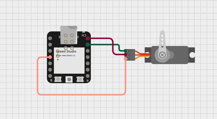
Wiring (follow the standard servo color coding):
| Servo Motor | Colour | Connection |
|---|---|---|
| Signal | Orange | GPIO 3 (XIAO pin D3) |
| VCC | Red | 5 V external power (positive) |
| GND | Brown | Common ground (servo GND + XIAO GND) |
Note: The servo’s red wire must never be connected to the XIAO’s 3.3 V or 5 V pin. The XIAO cannot supply the required current, and this could damage the board. Always use an external 5 V supply and tie the grounds together.
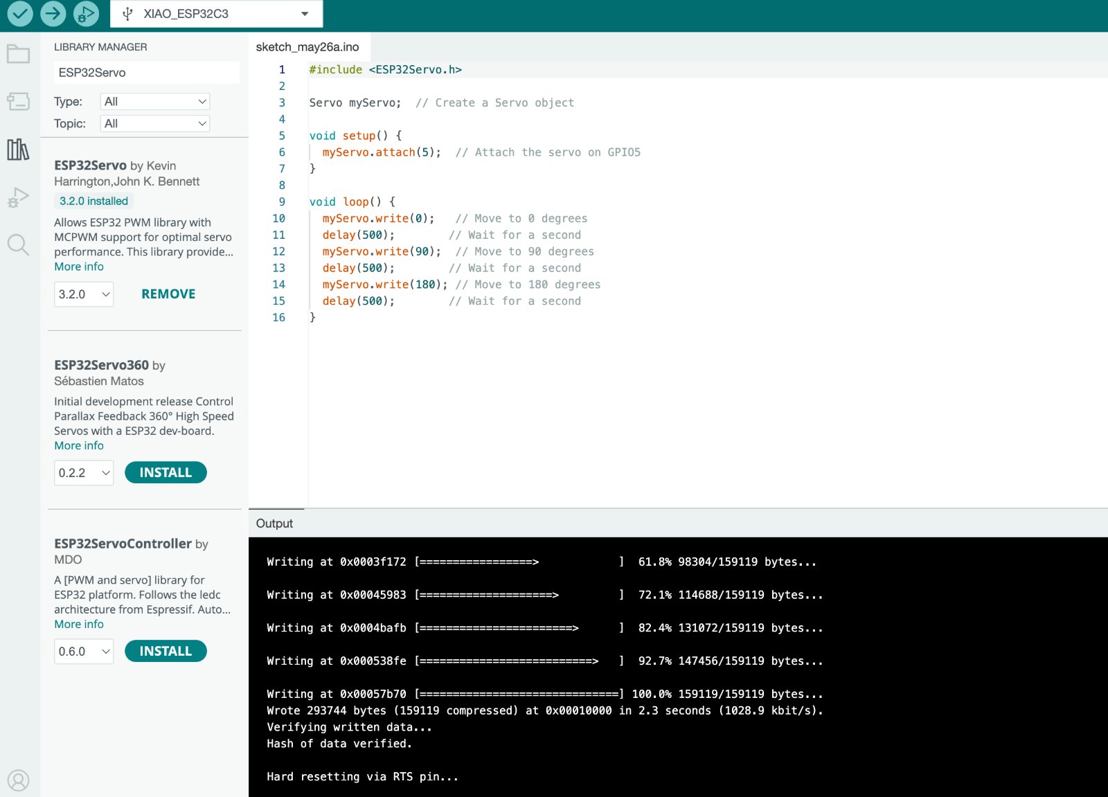
Library used: ESP32Servo — this library is specifically written for ESP32-based boards and handles the low-level PWM timing correctly. Install it via the Arduino Library Manager.
Code explanation
The program makes the servo sweep smoothly from 0° to 180° and back.
#include <ESP32Servo.h>

Servo myServo;

void setup() {
  myServo.attach(5);
}

void loop() {
  myServo.write(0);
  delay(500);
  myServo.write(90);
  delay(500);
  myServo.write(180);
  delay(500);
}
How it works:
#include <ESP32Servo.h>brings in the necessary PWM timing functions.- In
setup(), the servo is attached to GPIO5. - In
loop(), the sketch writes 0°, 90°, and 180° with delays between positions.
Problems Encountered & Solutions
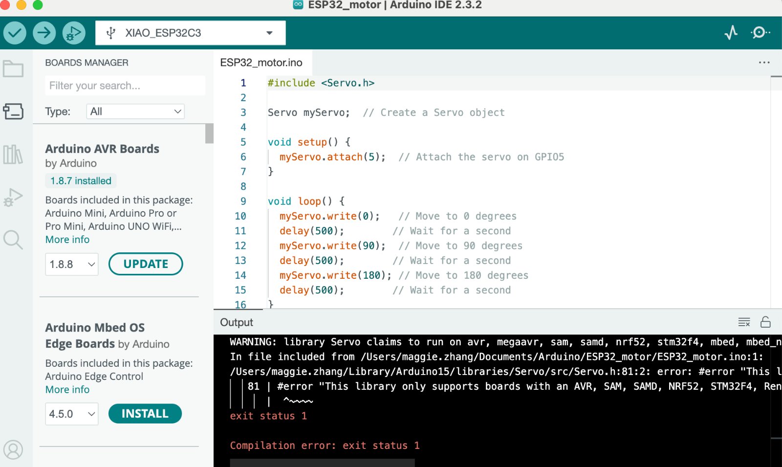
Problem 1: The servo motor did not move.
Solution: After checking the wiring and the code, I found the warning: library Servo claims to run on AVR. I changed the library to ESP32Servo.h and uploaded again. The servo motor moved.
Problem 2: The servo only twitched or moved weakly, and the XIAO board sometimes reset when the motor tried to turn.
Solution: I first powered the servo from the XIAO’s 5 V pin over USB. Our group measurement showed the SG90 can draw about 0.31 A when moving — far more than the board regulator can supply safely. I disconnected the red wire from the XIAO, powered the servo from an external 5 V supply, and tied servo GND and XIAO GND together so the PWM signal had a common reference. After that, the servo swept smoothly without brownouts or resets.
Source file (Arduino sketch): ESP32_motor.ino — XIAO ESP32-C3 + servo motor (same code as on this page).