Week 04: Embedded Programming
Some Backgrounds
Since I almost no background in chips or embedded systems, I first spent some time just understanding basic concepts before touching any code or hardware.
I watched a few introductory videos and also asked Perplexity to clarify key terms, so that later steps in the assignment would feel less “mysterious” and more under control.
I began with the concept of a datasheet, which is a technical document provided by the manufacturer of a component or chip. It describes what the part can do (its functions and application scenarios), key performance parameters such as operating voltage, current limits, speed, and precision, and also the pin definitions and usage notes.
From there, I learned that an SoC (System on Chip) integrates the CPU, memory, and peripherals into a single chip, like a tiny self‑contained computer. In a typical microcontroller system, the CPU is responsible for computation and control, Flash/ROM stores the program and long‑term data, RAM holds temporary variables during execution, and peripheral modules such as GPIO, UART, I2C, SPI, and ADC act as the “hands and senses” that talk to the outside world.
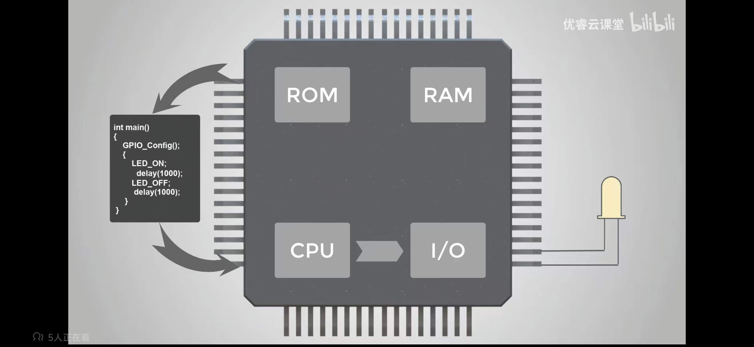
Next, I focused on input/output interfaces, because they are exactly where code meets hardware. GPIO pins can work in digital mode (pure on/off, such as turning an LED on or off or reading a button press) or in analog mode (continuous values, such as brightness or temperature). I also looked at communication protocols: I2C uses just two lines and can connect multiple devices like a shared bus, SPI is generally faster but requires more wires, and UART is a simple serial channel that is very common for debugging or talking to modules like GPS or Bluetooth. Along the way, I realized how important GND (ground) is: it acts as the common reference point, and all connected devices must share the same ground to “understand” each other’s voltages correctly.
To choose a concrete board for my assignment, I compared two very small development boards from Seeed Studio: XIAO RP2040 and XIAO ESP32C3. Both are thumb‑sized and breadboard‑friendly, but they target slightly different roles.
XIAO RP2040 uses a dual‑core ARM Cortex‑M0+ chip from Raspberry Pi and focuses on stable offline control, making it great for learning basic microcontroller concepts without worrying about networking. XIAO ESP32C3 is based on a RISC‑V core from Espressif, runs at around 160 MHz, and integrates Wi‑Fi plus Bluetooth 5.0, which is ideal for IoT and connected projects.
| Feature | XIAO ESP32C3 | XIAO RP2040 |
|---|---|---|
| Architecture | RISC-V 32-bit @ up to 160 MHz | ARM Cortex-M0+ dual-core @ 133 MHz |
| Wireless | Wi-Fi + BLE 5.0 | None |
| Best for | IoT / networking / wearables | General embedded / local control |
For my personal workflow and interests (especially IoT‑style, connected, “talking” devices that can send data or notifications), the XIAO ESP32C3 felt more aligned. In simple words, I see the RP2040 as a tiny computer without internet, very clean for learning fundamentals, and the ESP32C3 as a tiny IoT computer that can easily send data wirelessly. That’s why I chose the XIAO ESP32C3 as the main board for my Week 4 simulations and experiments, and all the later Wokwi and Arduino steps are built on top of this initial understanding.
Simulation Environment Setup
For Week 4, I focused on simulating and then gradually moving to real microcontroller experiments in a way that felt beginner-friendly and low-risk for me. I chose XIAO ESP32C3 as my main board because it is small, has built‑in Wi‑Fi and Bluetooth, and is very suitable for future IoT‑style projects I might want to do. I started in Wokwi, a free, browser‑based simulation environment that supports Arduino, ESP32, and the XIAO series. Working in simulation helped me build confidence with code and wiring before touching any real hardware.
Example 1: Blinking LED in Wokwi
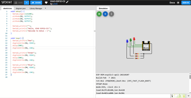
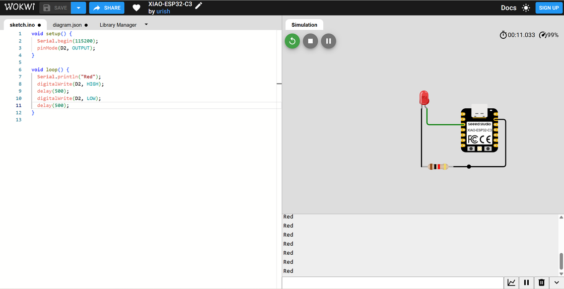
After creating an account and logging into Wokwi, I opened a new project and selected the XIAO ESP32C3 board. By default, the project includes some onboard LEDs, but to make the behavior more explicit, I removed the default yellow and green LEDs and added an external LED connected to pin D2 (with a resistor in series, as recommended in basic electronics practice). Then I wrote a simple Arduino sketch to toggle the LED and verify the digital output (GPIO) behavior:
void setup() {
  Serial.begin(115200);
  pinMode(D2, OUTPUT);
}

void loop() {
  digitalWrite(D2, HIGH);
  delay(500);
  digitalWrite(D2, LOW);
  delay(500);
}
In the simulation, the LED blinked reliably: on for 0.5 seconds, off for 0.5 seconds, repeating in a loop. This confirmed that the GPIO pin configuration and timing logic worked as expected, without any risk of wiring mistakes or burning components. Conceptually, this example helped me connect the idea of “digital output” with something very visual and intuitive: an LED that simply turns on and off.
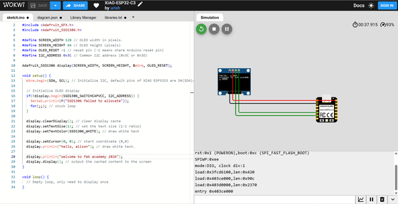
Example 2: OLED Display with I2C in Wokwi
After getting comfortable with a single LED, I moved on to a slightly more complex example: driving an SSD1306 OLED display over I2C. In a new Wokwi project, I again selected the XIAO ESP32C3, then added an SSD1306 OLED module. According to the XIAO ESP32C3 pinout, I wired:
- SDA of the OLED → D4 (SDA)
- SCL of the OLED → D5 (SCL)
- VCC → 3.3V
- GND → GND
I used the Adafruit GFX and Adafruit SSD1306 libraries to display a personalized message:
#include <Wire.h>
#include <Adafruit_GFX.h>
#include <Adafruit_SSD1306.h>

#define SCREEN_WIDTH 128
#define SCREEN_HEIGHT 64
#define OLED_RESET   -1
#define I2C_ADDRESS  0x3C

Adafruit_SSD1306 display(SCREEN_WIDTH, SCREEN_HEIGHT, &Wire, OLED_RESET);

void setup() {
  Wire.begin(D4, D5);  // XIAO ESP32C3: SDA = D4, SCL = D5

  if (!display.begin(SSD1306_SWITCHCAPVCC, I2C_ADDRESS)) {
    Serial.println(F("SSD1306 allocation failed"));
    for(;;);
  }

  display.clearDisplay();
  display.setTextSize(1);
  display.setTextColor(SSD1306_WHITE);
  display.setCursor(0, 0);
  display.println("hello, alison.");
  display.println("welcome to");
  display.println("fab academy 2026");
  display.display();
}

void loop() {
  // Nothing here – text is static
}
At first, the compilation failed with a fatal error: Adafruit_GFX.h: No such file or directory. This reminded me that even in a friendly environment, I still need to manage libraries properly. After downloading and installing the required libraries, the project compiled and ran successfully in Wokwi, and the OLED showed my customized message. Compared with the blinking LED, this step helped me practice I2C wiring and understand that multiple devices can share the same two data lines as long as they have different addresses.
Moving to Real Hardware: Arduino IDE + XIAO ESP32C3
Once I was comfortable with the simulation, I switched to real hardware using Arduino IDE. Arduino IDE is an open‑source development environment that makes it easy to write, compile, and upload sketches to boards such as the XIAO ESP32C3. I followed the official getting started guide for XIAO ESP32C3 to install the ESP32 board support package, select the correct board in the Tools menu, and set the right COM port. After successful installation, I could flash code directly to my physical board.
For the physical experiments, I prepared:
- A XIAO ESP32C3 module (soldered with headers so it can plug into a breadboard)
- A breadboard
- A red LED and a current‑limiting resistor
- A Grove Temperature & Humidity Sensor (DHT11)
- Some jumper wires / Dupont cables
Soldering the XIAO’s pin headers was the first “hands‑on” step: I needed to make sure the pins were straight and firmly attached so that the board could sit stably on the breadboard.
After that, I replicated the LED blink example from Wokwi in the real world. I connected the LED (with resistor) to pin D10 (according to the XIAO documentation) and GND, then adapted my earlier code and increased the delay from 500 ms to 2000 ms, so the blink became more obvious:
void setup() {
  Serial.begin(115200);
  pinMode(10, OUTPUT);
}

void loop() {
  digitalWrite(10, HIGH);
  delay(2000);
  digitalWrite(10, LOW);
  delay(2000);
}
When I uploaded the sketch, the physical LED blinked every 2 seconds, matching my code. This transition from virtual to physical made the abstract “pinMode” and “digitalWrite” calls feel much more concrete.
Reading Sensor Data: Grove DHT11 Temperature & Humidity
Next, I explored input rather than just output by using the Grove Temperature & Humidity Sensor (DHT11). I followed the official wiring table:
- 5V → Red wire
- GND → Black wire
- Not Connected → White wire
- Data (D2) → Yellow wire
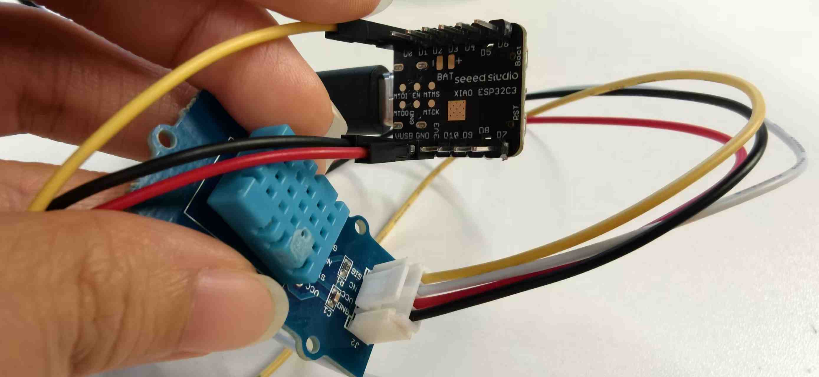
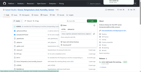
Because the Grove connector is convenient, I tested it first without a breadboard by connecting the sensor’s signal pin to a suitable GPIO pin on the XIAO using a Dupont cable. After confirming the wiring was correct (power, ground, and data all going to the right places), I installed the DHT library inside Arduino IDE and opened the sample code from the library’s examples.
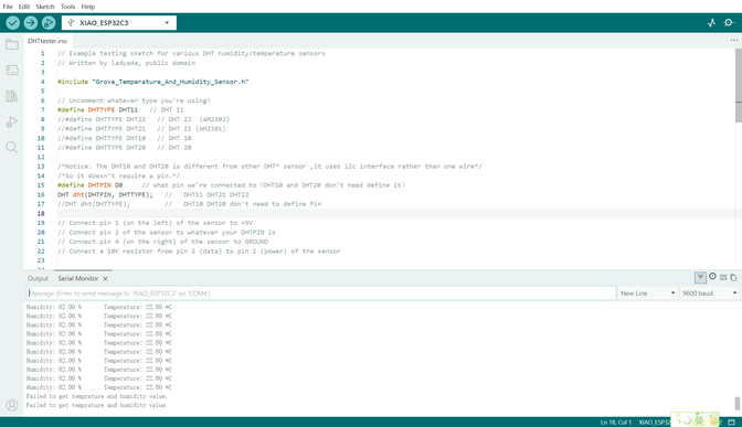
On the first try, the sketch failed to work properly because the example was configured for DHT22 by default, but my physical sensor was a DHT11 module. Once I changed the type in code from DHT22 to DHT11, the readings started to appear correctly in the Serial Monitor, showing temperature and humidity values updating over time.
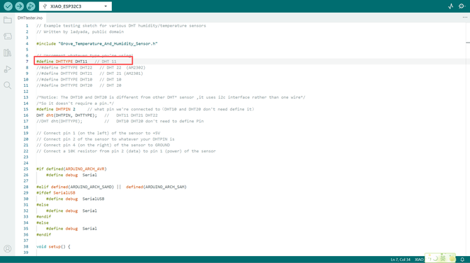
This small debugging moment reinforced two key habits for me: carefully matching hardware versions, and reading the library documentation and comments instead of assuming “default settings” will always match my sensor.
Reflection
Overall, my Week 4 workflow moved in three steps: simulate basic behavior (blinking LED) in Wokwi, simulate a more complex I2C peripheral (OLED), and then replicate similar ideas on real hardware with Arduino IDE (LED + DHT11 sensor). This progression felt natural and aligned with how I usually learn digital tools: start with a safe sandbox, then gradually bring it into the “real world.” The combination of XIAO ESP32C3, Wokwi, and Arduino IDE gave me a smooth path from concept to practice, and the small bugs (like missing libraries and wrong sensor type) became good learning checkpoints instead of blockers.