Overview
This week was about CNC milling: subtractive manufacturing where the computer interpolates between points to carve complex geometries from a block of material. The pipeline is simple, CAD model → G-code → machine executes , but everything interesting happens in the planning before the spindle ever touches the stock.
Two projects this week: a plywood tongue drum built with finger joints, pentatonic tuning, and a botanical engraving motif; and the beginning of a CNC mirror frame inspired by my grandmother Maya's botanical illustrations, the physical counterpart to the Blender model from Week 2, destined for the Maya's Mirror installation.
As part of the group assignment, we did the lab's safety training and then characterized the machine, runout, fixturing, speeds, feeds, and materials, before committing to our individual projects. That baseline made the tongue drum parameters much easier to dial in.
"The machine time is almost the smallest part of the job. The hours go into everything before you press Run."
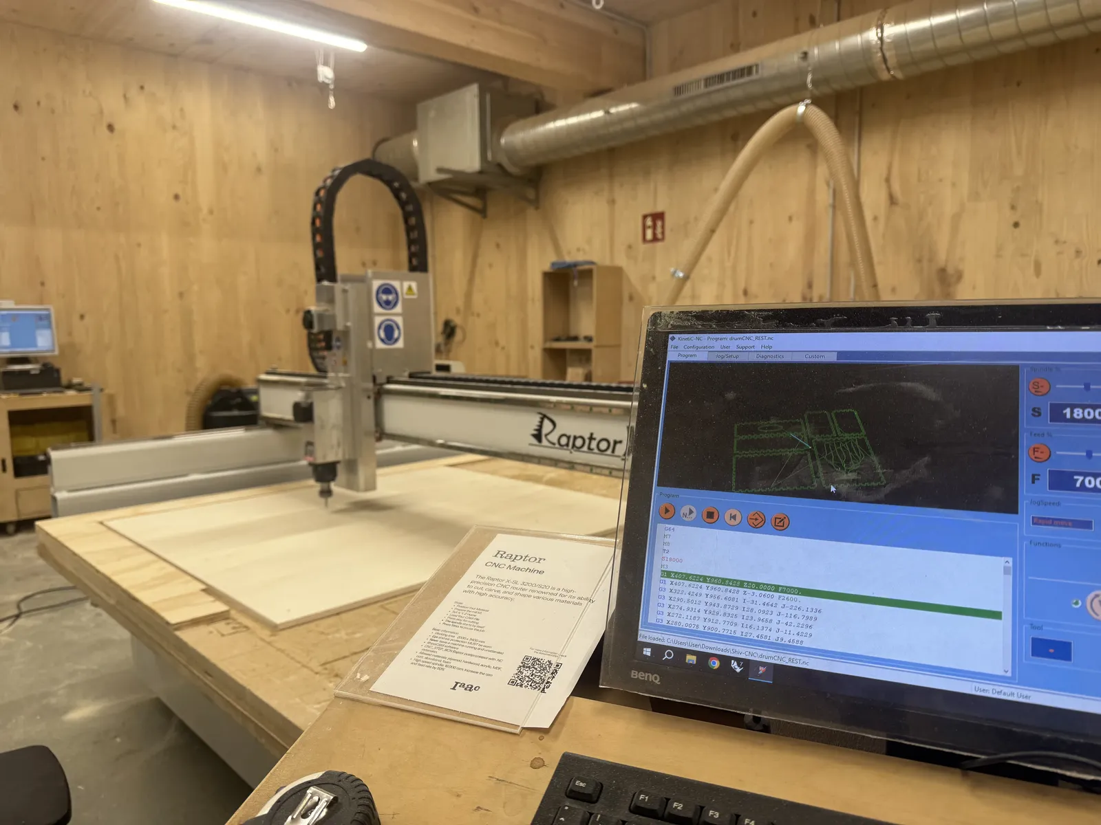
The Raptor X-SL at Fab Lab Barcelona, G-code loaded on the controller, plywood fixtured and ready. Spindle speed: 1600 RPM.
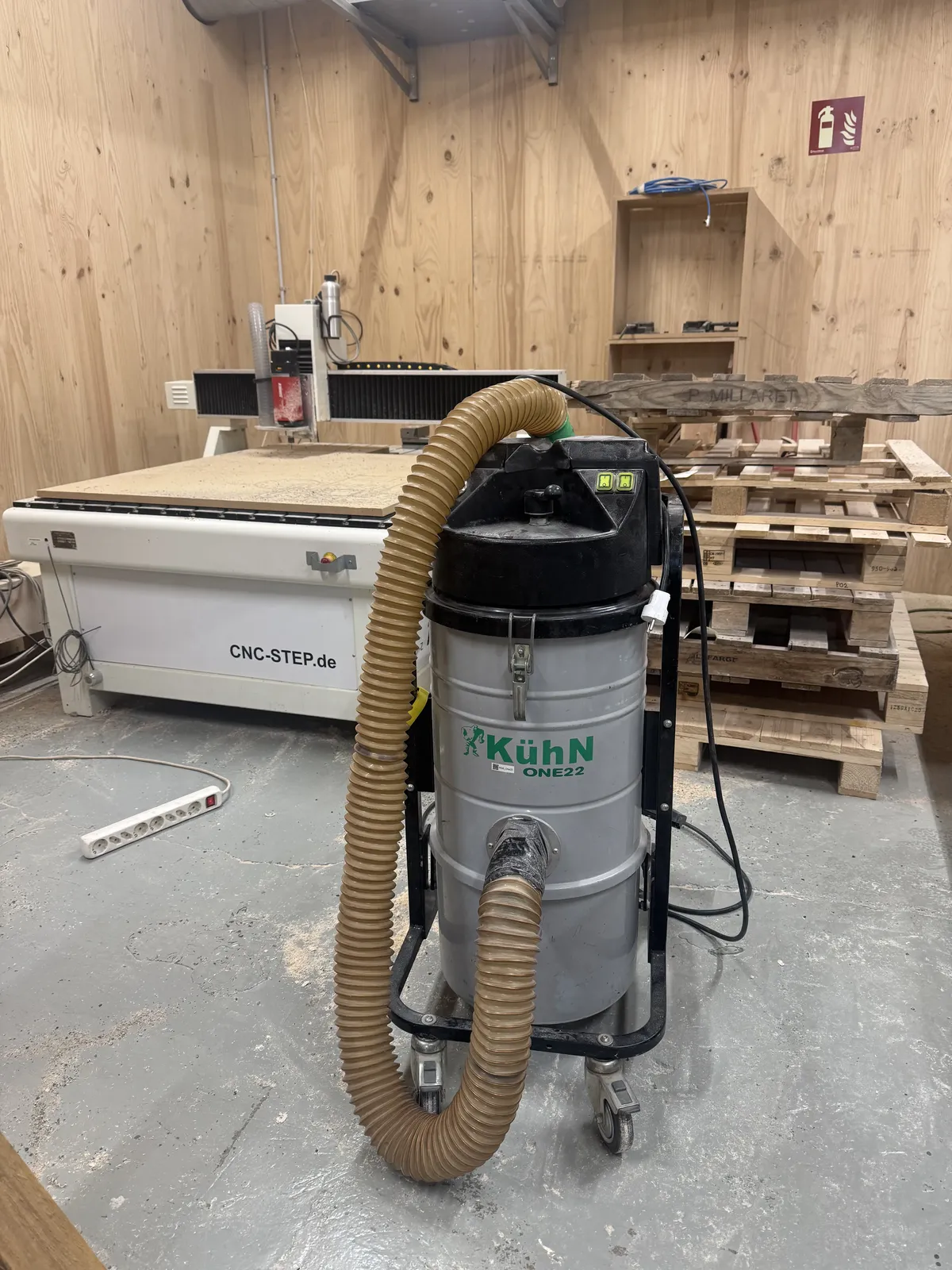
The Kühn ONE22 industrial extractor runs the entire time the machine is cutting. You don't start without it.
What is CNC Milling?
CNC milling is subtractive manufacturing, you start with material and remove what you don't need. Most work is 2.5D: the bit moves in X and Y, stepping down in Z across three main operations: engraving, pocketing, and profiling. True 3-axis surface work is also possible, using an STL rather than a mesh.
Choosing the Right Milling Bit
Shape, diameter, blade length, and flute count all determine what you can cut and how fast. A mill bit looks like a drill bit but costs ~€60 versus ~€2, because it has cutting edges along its sides, not just the tip. Treat them accordingly.
Flute types each have a trade-off: upcut pulls chips out (great for through-cuts, can tear the top surface); downcut gives a cleaner top but chips stay in the pocket; compression combines both and is the best choice for plywood. This week we used a 6 mm flat end mill for drilling, profiling, and pocketing, and a 6 mm ball end mill for 3-axis finishing passes.
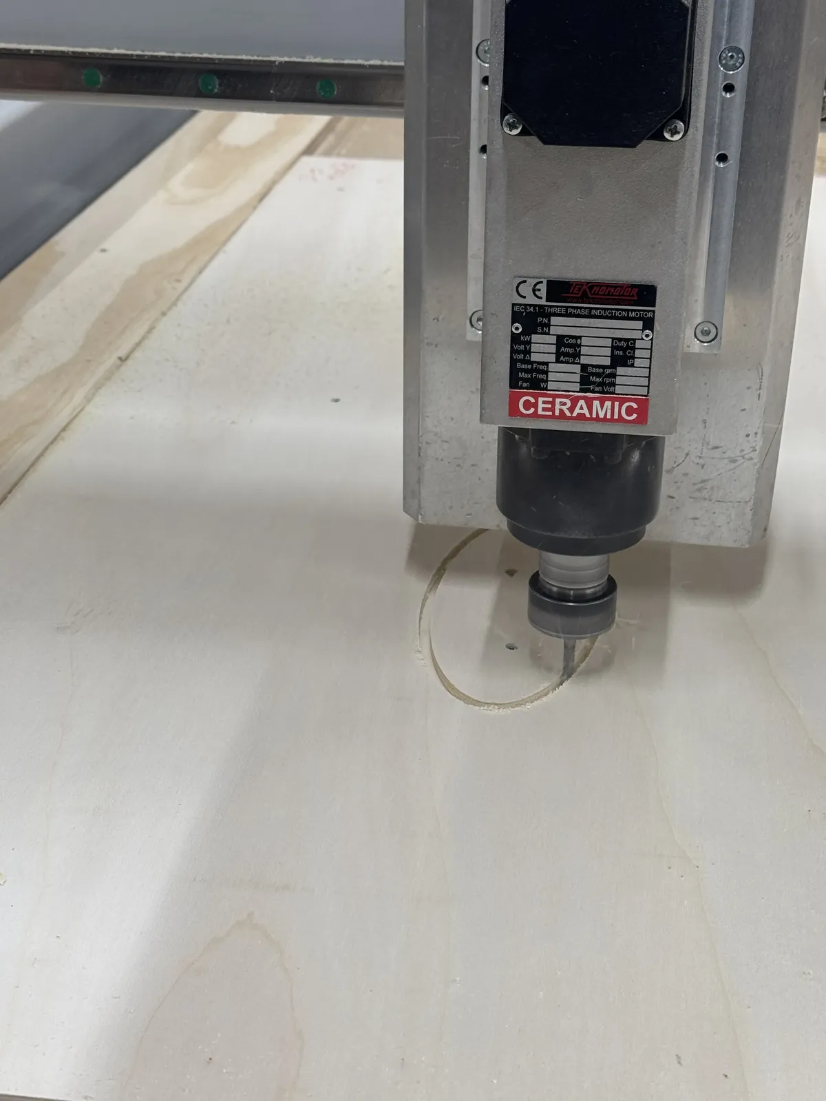
The ceramic spindle at rest. At 1600 RPM this is what does the actual cutting, treat the bit with the same respect as the machine.
Feeds, Speeds & Key Parameters
Three things to nail before hitting Run: cutting speed / feed rate (too slow burns the material; too fast snaps the bit), spindle RPM (always verify on the controller, some machines ignore the G-code value), and cut depth per pass (rule: rough depth = ½ × bit diameter, so 15 mm stock with a 6 mm bit = 3.1 mm per pass across 5 passes).
Never pause mid-cut to change bits unless the program is explicitly designed for a tool change. Plan your operation order and don't deviate.
Safety Training
Before touching the machine we went through the lab's CNC safety protocol. The Raptor runs a ceramic spindle at high RPM, wood dust at that volume is a real respiratory hazard. The Kühn industrial extractor runs the entire time; you don't start without it.
The full kit: FFP2 mask (mandatory, not a surgical mask), safety glasses, and gloves for handling stock and removing cut pieces. No gloves near the spinning spindle. One practical issue, wearing safety glasses over prescription glasses is uncomfortable and slightly ridiculous, but non-negotiable. Splinters from freshly cut plywood edges are also a real hazard; gloves earn their keep there.

FFP2 mask plus glasses-over-glasses. Uncomfortable. Non-negotiable. The moment the spindle starts and the extractor kicks in you understand why every item on that list is there.
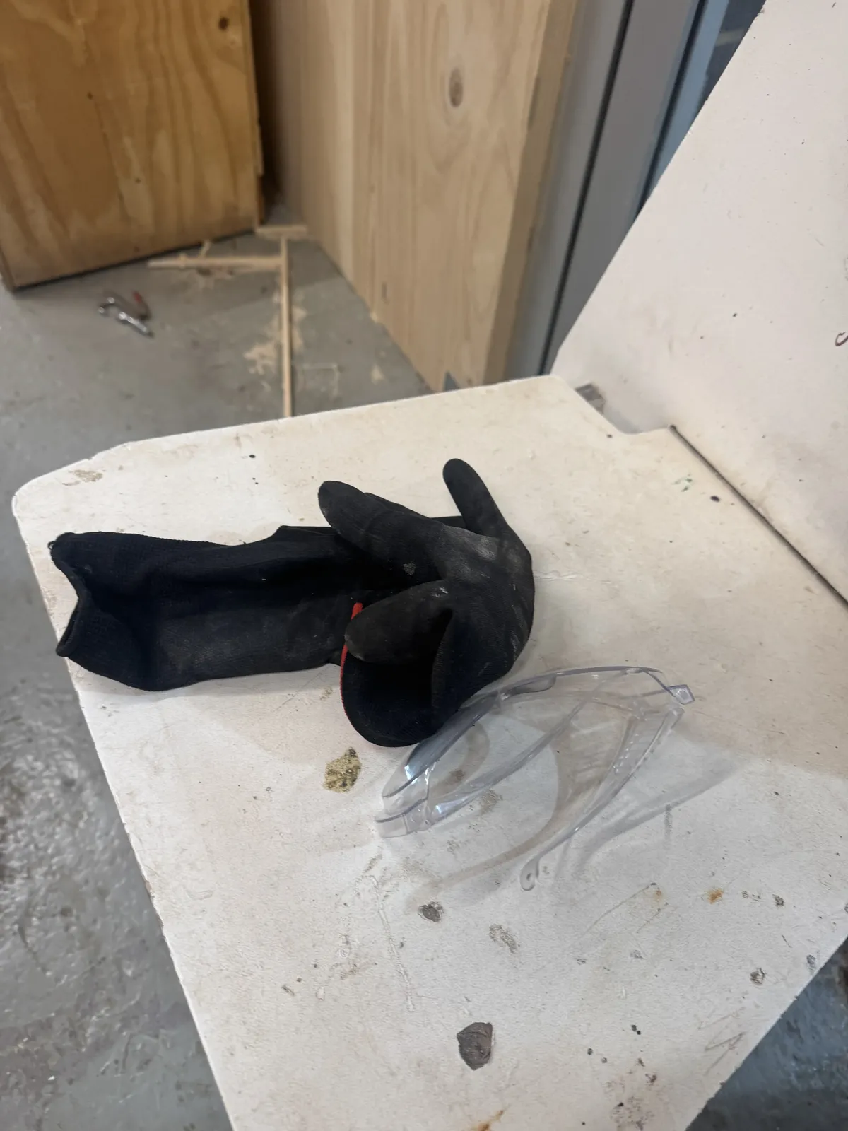
Gloves and goggles ready before starting, mandatory for handling stock and removing cut pieces.
Fixturing & Bed Setup
The bed is oriented so the long axis is X, the short axis is Y, and their intersection is origin (0, 0, 0). Max material height is 80 mm. Fixture strategy determines whether the job succeeds, material that moves mid-cut ruins everything.
- Place screws close to the object, not only at corners, especially for pocketing.
- Use mouse ears (small circles at corners) to prevent lifting at rounded edges.
- Use dog-bone fillets at internal corners, a round bit cannot cut a sharp 90° corner, so you design the relief in deliberately.
- Check screw clearance with the 12 mm bit before running, there must always be room.
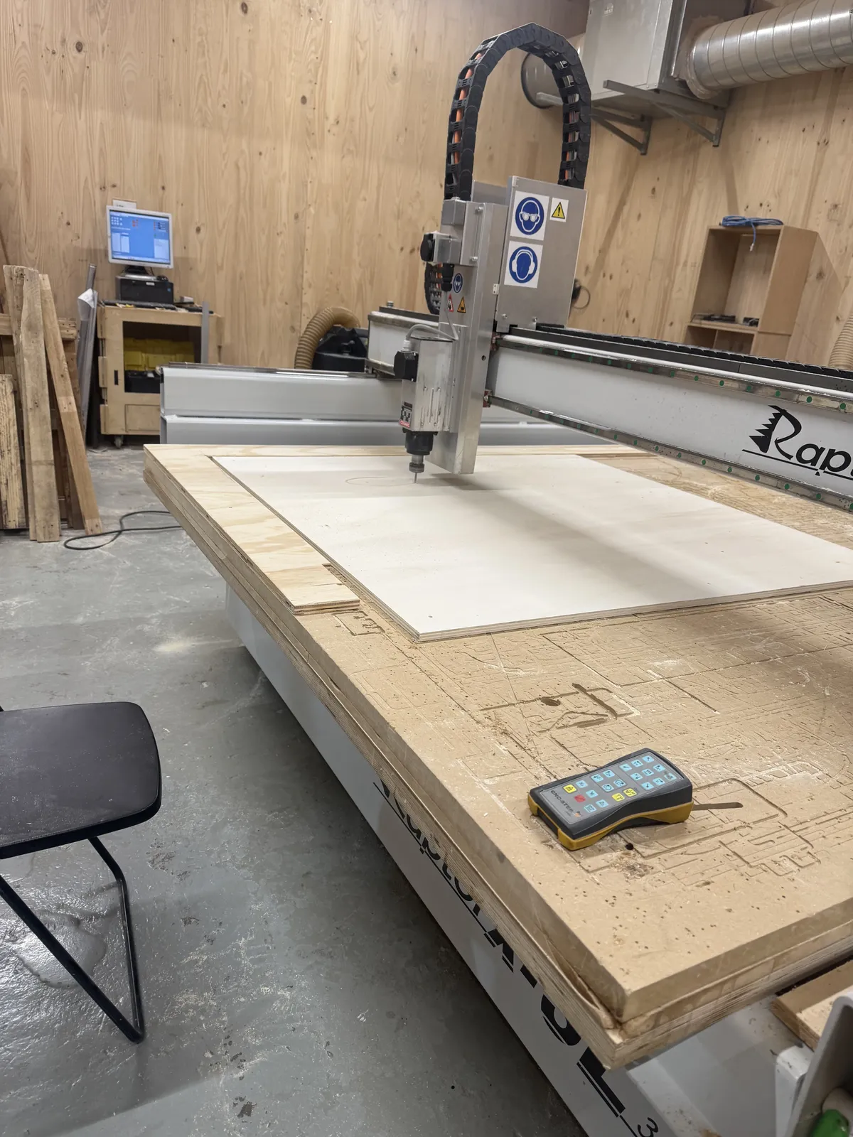
1220 × 1217 × 15 mm plywood fixtured to the Raptor bed. The remote pendant (yellow) is how you jog the machine to set origin before running.
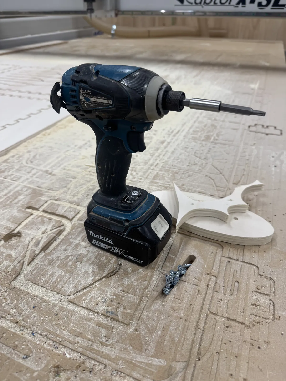
The fixturing kit: Makita impact driver and screws. The white piece beside it is a test cut, dog-bone fillets visible at each internal corner.
RhinoCAM Workflow
G-code syntax differs between machines, so we use RhinoCAM as the post-processor bridge. The output file contains material info, test settings, and the full operation sequence.
Parameters — Tongue Drum
Stock: 1220 × 1217 × 15 mm plywood. All values loaded from the tool library rather than typed manually.
- Tool: 6 mm flat end mill — drilling and profiling
- Spindle RPM: 1600
- Feed rate (drill / plunge / cut): 2600 mm/min
- Clearance plane: stock max + 20 mm Z
- Total cut depth: 15.3 mm | Depth per pass: 3.1 mm (5 passes)
- Cut direction: climb — lateral movement only
- Entry / exit: none / none
- Bridges / tabs: outside profile cuts only
Setup Checklist
- Open RhinoCAM → Mill plugin → load tool library (30 tools).
- Review tool specs: length, diameter, RPM, cut rate, plunge rate. Cut rate is most critical.
-
Set up layers:
profile,screws,pocketing,engrave— colour-coded. - Define stock: align origin to 0, 0, 0. Use preset stock size; don't modify the alignment.
- Post-process: use ShopBot OK / Raptor depending on machine.
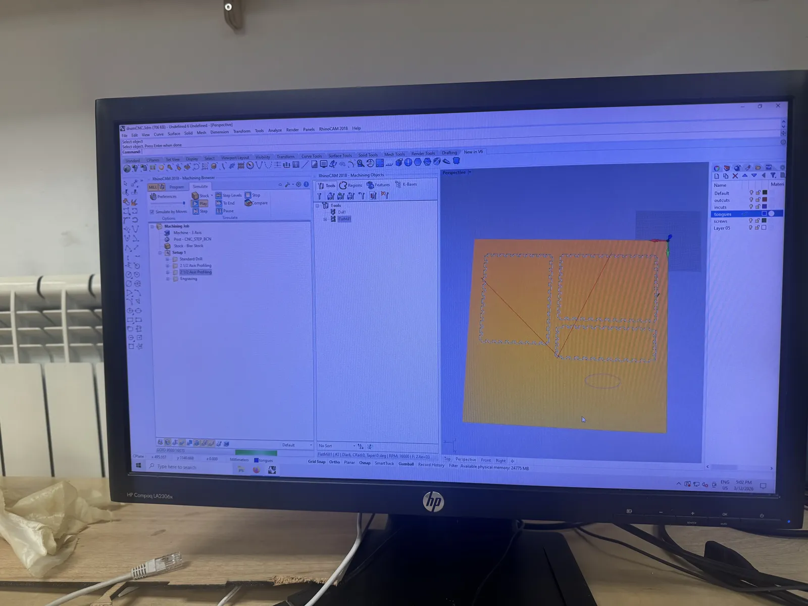
RhinoCAM simulation — the parallel finishing toolpath over the stock. Always run the simulation and check the bottom of the bed before exporting G-code.
2-Axis Operations
Screw operation first — 15 mm clearance, cut parameter 1. Material must be secured before any profiling starts.
Profiling: select lines → 2-axis profiling → Load from Tool. Set clearance plane manually. Cut direction: climb, inside/outside for closed curves. Outside cuts require bridges/tabs in Advanced Cut Parameters, leave everything else blank. Cut levels: 15.3 mm total, 3.1 mm per pass.
Pocketing: same tool and most parameters. Default leaves a 0.6 mm stock offset, always set it to 0 in Global Parameters → Cut Parameters. If you move the object, right-click → Regenerate Setup Strategies.
3-Axis Operations (STL workflow)
- Insert STL, place below Z = 0, confirm inside stock volume.
- Don't place too low, more material above = more roughing time.
- Horizontal Roughing: 6 mm flat, 75% stepover, 0.6 mm stock.
- Parallel Finishing: 6 mm ball, 0 stock, quality 25.
- Holes in the mesh need a capping surface, otherwise the finishing pass plunges through.
- Disable spiral paths; verify engage path in simulation.
Cutting in progress, screw operation complete, profiling underway.
Project: Plywood Tongue Drum
A pentatonic tongue drum cut from 15 mm plywood, six tongues tuned to a G2/A2/C3 scale, a 220 × 100 mm ellipse sound hole, finger joints on all four edges of the top and bottom panels, and a botanical motif engraved into the top.
How Tongue Drums Actually Work
A tongue drum is a pitched idiophone, meaning the material itself vibrates to produce sound, with no strings or membranes involved. Each tongue is a cantilever beam: fixed at one end (where it connects to the body) and free at the other. When you strike the free end, the tongue flexes and oscillates at its natural resonant frequency. That frequency becomes the pitch you hear.
The physics is the same as a diving board: a longer, thinner board flexes more slowly (lower frequency, lower pitch); a shorter, stiffer one snaps back faster (higher frequency, higher pitch). For a tongue drum, you control pitch by changing tongue length and tongue width. Length is the dominant variable, doubling the length drops the pitch by roughly two octaves.
Tuning: The Role of Tongue Length
The resonant frequency of a free-clamped beam follows: f ∝ (thickness × width) / length². That squared relationship on length is what makes it so sensitive, a small change in length has a large effect on pitch. In practice:
- Shorter tongue → higher pitch. The lowest note (G2) needs the longest tongue; the highest (C3) needs the shortest.
- Width affects both pitch and volume, a wider tongue moves more air and resonates louder, but also stiffens it, nudging the frequency up slightly.
- Thickness is fixed by the stock (15 mm plywood), so length and width are the only two tuning levers available in the design.
Getting from a target frequency to a tongue dimension requires working backwards through that formula. I used reference values from existing tongue drum designs and adjusted proportionally for 15 mm plywood, then verified in simulation before cutting.
Optimising for Volume: The Body as Resonator
The tongue produces the pitch, but the body cavity amplifies it. The enclosed air inside the drum acts as a Helmholtz resonator, the box has a natural resonant frequency determined by its internal volume and the size of the sound hole opening. When the body's resonant frequency is close to the tongue's fundamental, the two reinforce each other and the instrument is significantly louder.
This created a real design tension: a larger body gives more resonance and volume, but the CNC bed constrains total panel size, and the finger joints need enough material to be structurally sound. Three competing constraints:
- Body volume — larger = louder and richer sustain, but increases material use and cut time.
- Sound hole size — the 220 × 100 mm ellipse was sized to tune the Helmholtz frequency toward the mid-range of the pentatonic scale (roughly A2), so the body amplifies the most-used notes most strongly.
- Finger joint depth — joints that are too shallow pull apart; too deep and they eat into the tongue root area, destabilising the tuning of the lower notes whose tongues sit closest to the edges.
The CNC Constraint: Kerf and Tongue Root
The 6 mm bit introduces kerf — material removed by the cut itself. For the tongue cuts, this means each slot is 6 mm wide regardless of how thin you draw it in CAD. That kerf width affects the effective tongue width (slightly narrower than designed) and the stiffness at the root.
The root is the most critical dimension: this is where the tongue is clamped to the body, and where stress concentrates when the tongue flexes. Too thin a root and the tongue cracks over time. Too wide and the tongue can't flex freely, killing sustain. I added a small radius at the root of each tongue cut, both to reduce stress concentration and because the dog-bone fillet that the round bit requires there actually functions acoustically, giving the tongue a cleaner pivot point.
In short: the dog-bone, usually a pure fabrication workaround, became an acoustic feature.
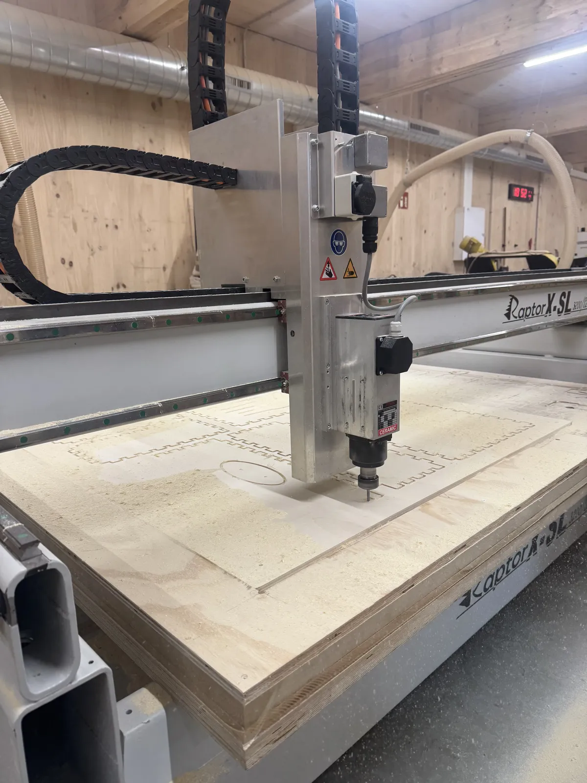
Raptor mid-cut: finger joints along the top edge and the ellipse sound hole are through-cut first. Dog-bone reliefs are visible at each internal corner.
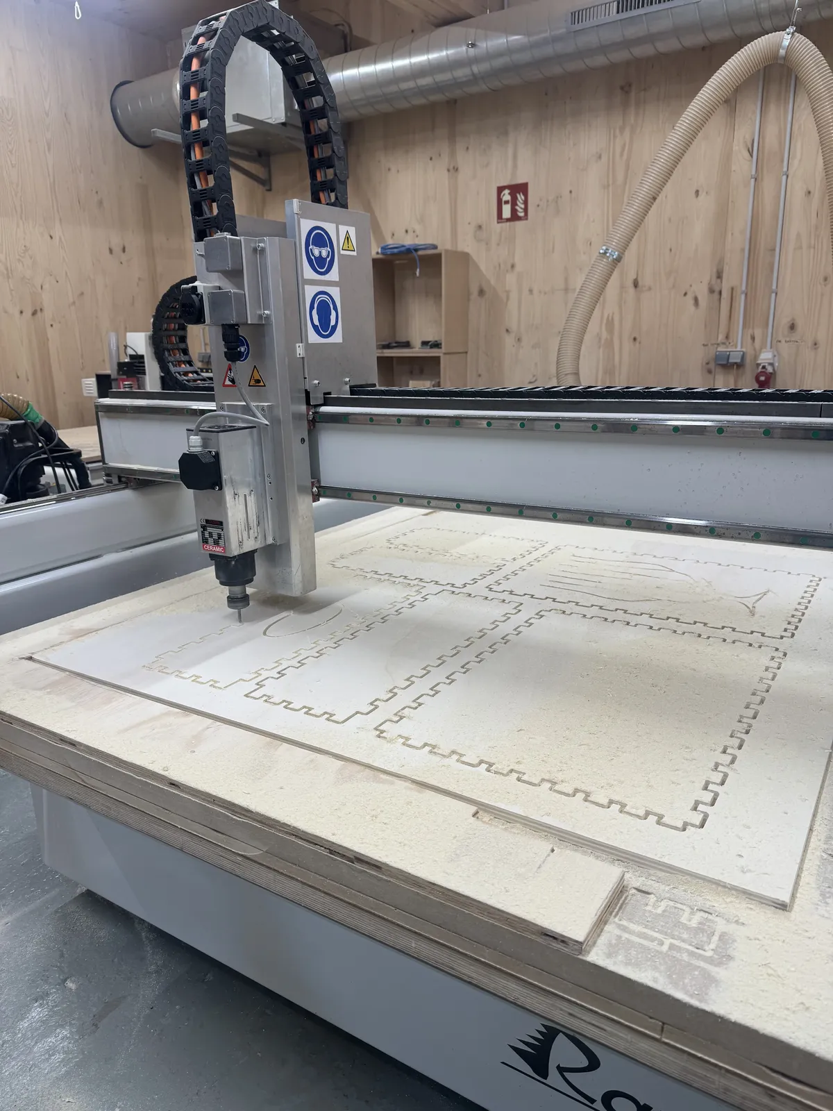
Finger joints fully cut, botanical engraving beginning in the lower right. The engraving operation runs last, it's the most delicate pass.
The botanical motif fully engraved. The same visual language as Maya's Mirror, a thread running through the whole project.
Full cut sequence, profiling through to engraving.
Project: Maya's Mirror Frame
The ornate frame I modelled in Week 2, inspired by my grandmother Maya's botanical illustrations, is coming off the screen and into wood. The same geometry that exists as a Blender mesh will be CNC-milled from plywood as the physical frame for the Maya's Mirror installation.
"The wood grain will do what no screen rendering can , it will carry the material memory of something alive."
Why CNC?
The frame has both flat engraved pattern (vines, botanical linework) and raised 3D sculpted relief (flowers, depth in the ornamental borders). That mix makes it a natural 3-axis CNC job, laser can't give depth, and 3D printing wouldn't have the warmth of wood grain that connects back to nani's hand-drawn work.
CNC Strategy
- Horizontal Roughing: 6 mm flat, 75% stepover, 0.6 mm stock. Clears the bulk fast.
- Parallel Finishing: 6 mm ball, 0 stock, quality 25. Follows surface contours to reveal the botanical relief.
- Outer frame silhouette: separate 2.5D profiling operation, cut outside the line, bridges to hold in place until the final pass.
- Any holes in the mesh need a capping surface so the finishing pass doesn't plunge through.
Time Estimation
RhinoCAM gives a machine time estimate in the Setup info panel. The formula to plan your day:
(Machine time + 15 min setup + 15 min teardown) × 2 = total time to budget
The ×2 accounts for post-processing: sanding, removing bridges, finishing edges. It's not pessimistic, it's accurate.
Problems & Fixes
The wood was enormous, measure twice
The stock sheet was 1220 × 1217 mm, bigger than I expected to be handling. Before you can fixture anything you have to physically lift, position, and align it on the bed. We measured twice before screwing anything down. At this scale, an offset origin wastes both time and material with no recovery path.
Dog-bone fillets — the internal corner problem
A round bit physically cannot cut a sharp 90° internal corner, it leaves a curved radius equal to its own diameter. For the tongue drum's finger joints, this meant tabs wouldn't seat flush without clearance. The fix is the dog-bone fillet: a small circular cutout at each internal corner that gives the mating piece room to slide in. It looks odd in the CAD but disappears once assembled. You can't design around physics, you design with it.
Pocketing left a skin of material
First pocketing pass left ~0.6 mm at the floor. The default stock offset in RhinoCAM pocketing is 0.6 mm and it's easy to miss because it feels intentional. Fix: Global Parameters → Cut Parameters → set stock to 0. Worth checking every single time you set up a pocket operation.
Toolpath didn't update after moving geometry
Repositioned the object in Rhino and the simulation still showed the old paths. RhinoCAM doesn't auto-update, right-click → Regenerate Setup Strategies every time geometry moves. Caught in simulation, which is the right place to catch it.
RPM not reading from G-code on the Raptor
The Raptor can silently ignore the spindle RPM in the G-code file and hold whatever was last set manually. Always verify the RPM on the Raptor control panel before running, the software value and the actual spindle speed are not always the same thing.
Group Assignment: Knowing the Machine
The brief was the lab's safety training plus characterizing the machine, runout, alignment, fixturing, speeds, feeds, materials, and toolpaths, before anyone cut their own project. The test cuts, parameter tables, and machine notes live on the group work page, linked in the sidebar.
What this changed for me was the idea that a CNC is something you can just point at a file and trust. It isn't. The same machine gives you a clean edge or a scorched, fuzzy one depending on a feed rate you chose, and the only way to know which you'll get is to make a small cut and look at it first. Running the test passes as a group, watching how the plywood reacted to different speeds and how much a sheet shifts if it isn't screwed down tightly enough, turned a list of abstract parameters into something I had actually seen behave.
That's also why I wasn't nervous committing a full 1220 mm sheet to the tongue drum. The numbers I loaded weren't guesses, they were the ones the group had already earned on scrap. Safety training landed the same way: it stops being a checklist and becomes obvious the moment the spindle spins up and the extractor roars, and you understand why the mask and the glasses and the no-gloves-near-the-spindle rule all exist.
Design Files & Hero Shot
The cut pieces, laid out before assembly. Getting them together was the real fight: the finger-joint teeth came out mismatched between mating panels, slots and tabs that should have lined up didn't, so the body wouldn't seat as cut. I had to trim several teeth back by hand before the panels would close. The shot below is the result as it came off the machine, pre-fitting.
The pieces with finger joints cut, before assembly. The teeth didn't match across mating panels, so several had to be trimmed by hand to get the body to close.
After trimming the mismatched teeth back by hand, the body finally closed. Here it is assembled, and tuned:
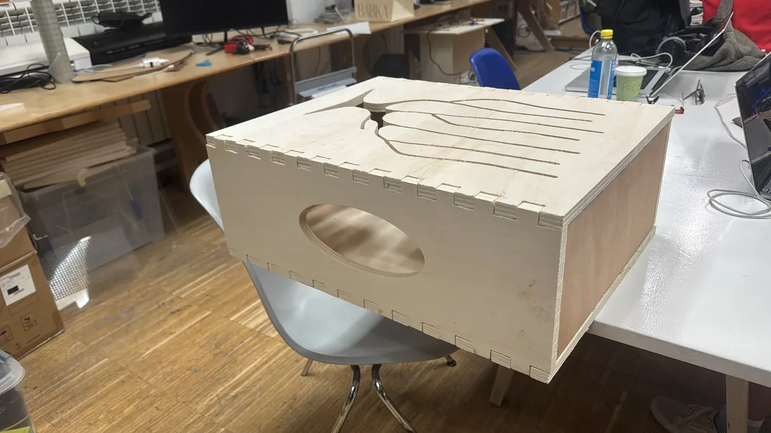
The finished drum, finger joints closed, the ellipse sound hole, and the botanical motif across the top. The same visual language as Maya's Mirror.
Played, the pentatonic tuning, audible. Each tongue's length sets its pitch; the body cavity amplifies it.
- tongue_drum_final.svg — Rhino source with all layers (profile, screws, pocketing, engrave)
- drumCNC_REST.nc — exported G-code for Raptor
