What It Finally Became
After every subsystem was packaged behind the carved frame, this is the resolved assembly. The exploded view pulls all seven layers apart, and the Fusion model holds the whole integration in one file, every part as its own body. The rest of this page is how it got here.
The full assembly render. This is the final integrated piece.
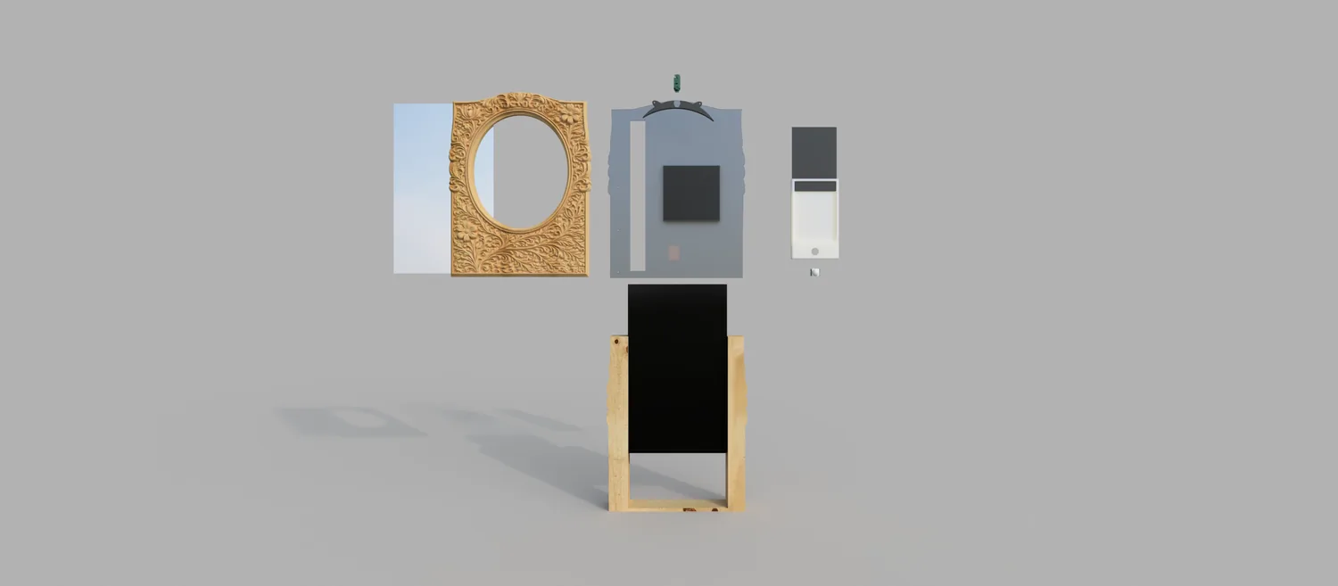
Exploded render, all seven layers.
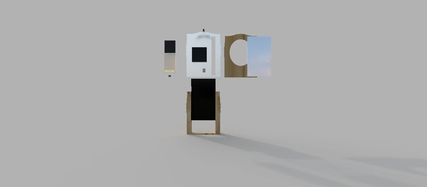
The same explosion from an angle.
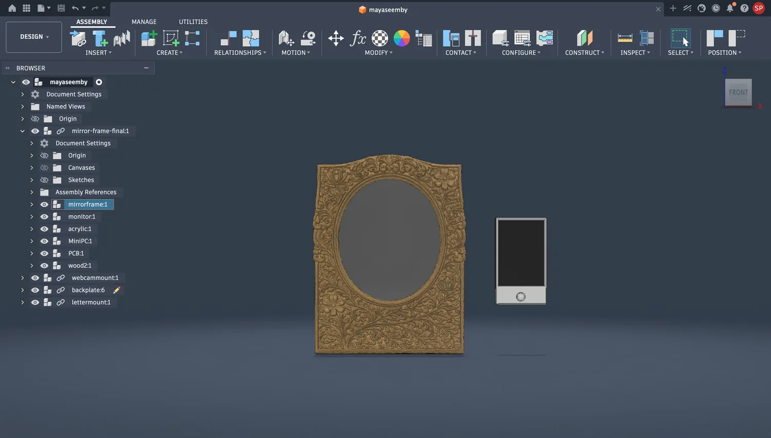
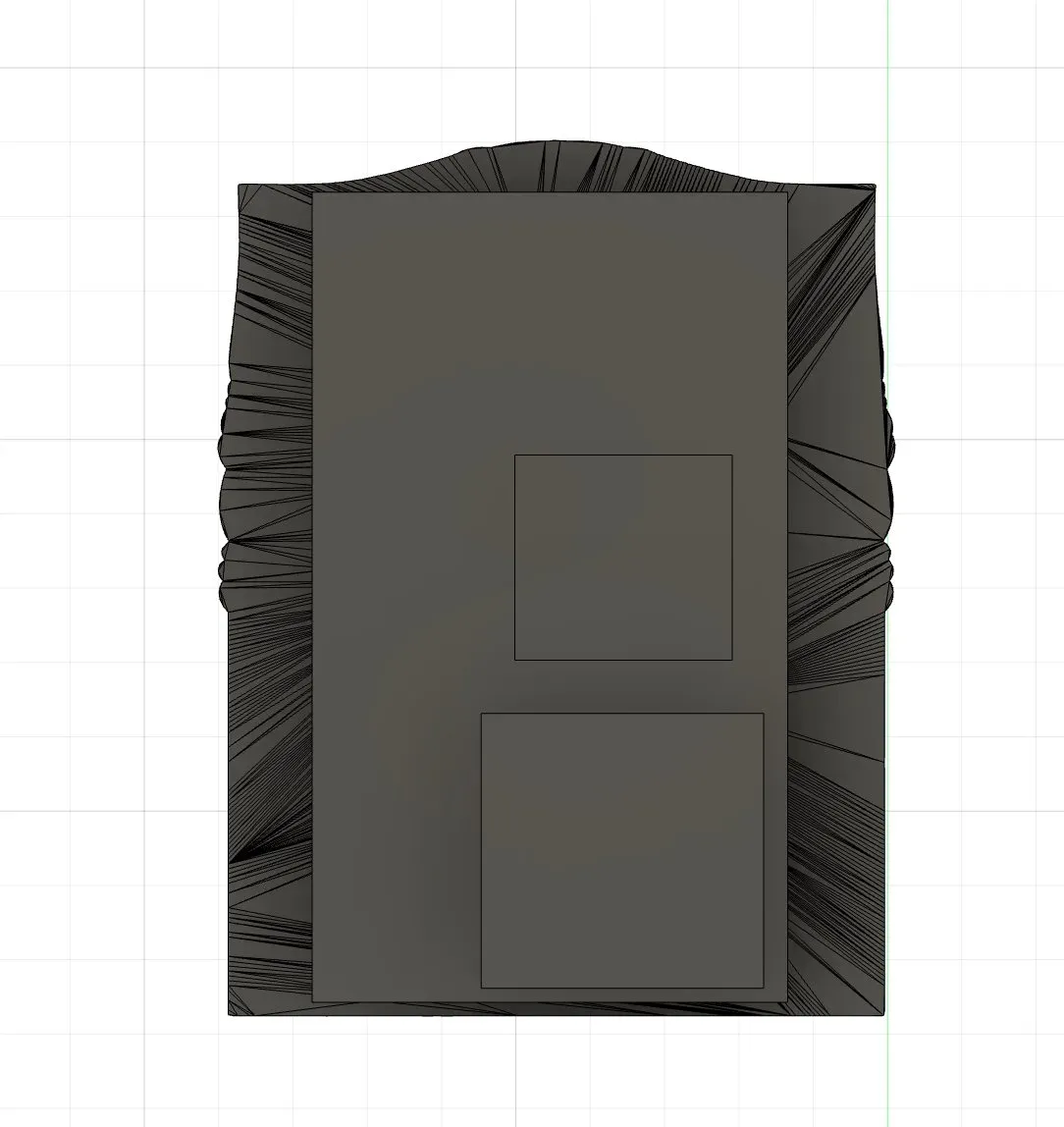
Fusion front view of the resolved assembly.
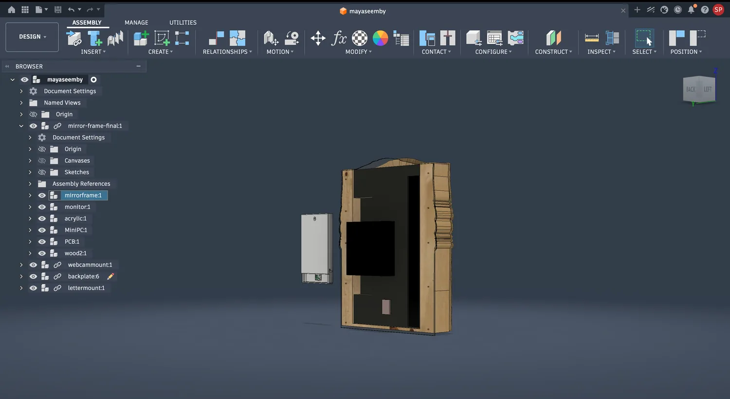
Fusion back view, every part named in the tree.
Overview
Design and document the system integration for your final project — bring every subsystem into one object that reads as a finished product, not a pile of parts.
Maya's Mirror is a one-way mirror that warps your reflection into my grandmother's botanical drawings when you approach. By this point every subsystem existed on its own — a monitor, a mini PC running the WebGL piece, a milled sensor node, a webcam, and my grandmother's laser-marked acrylic letter. System integration week was about packaging all of it behind one carved frame so it looks like a single object you'd hang on a wall, with nothing loose and nothing exposed.
The integration strategy, front to back: carved frame as the face → one-way acrylic + monitor → frosted acrylic back panel carrying the electronics → wood box sides sealing it, glued from pieces cut to the exact same outline, with a pocket left open at the top for monitor ventilation. Every component fixes to the layer behind it, so the whole stack is one rigid sandwich.
Planning the Integration
I started physical, not digital. Before committing any CAD I folded a paper / card maquette — an origami-style study of the final form — to feel the proportions of the frame, the screen opening, and the lower bezel where the sensor would live. Alongside it I worked out the layer thicknesses and spacing on paper: how deep the stack needed to be to fit the monitor, the mini PC, and the acrylic without fouling the frame.
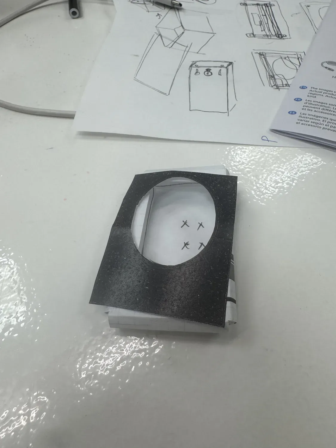
Paper maquette + concept sketches — the form study before any CAD.
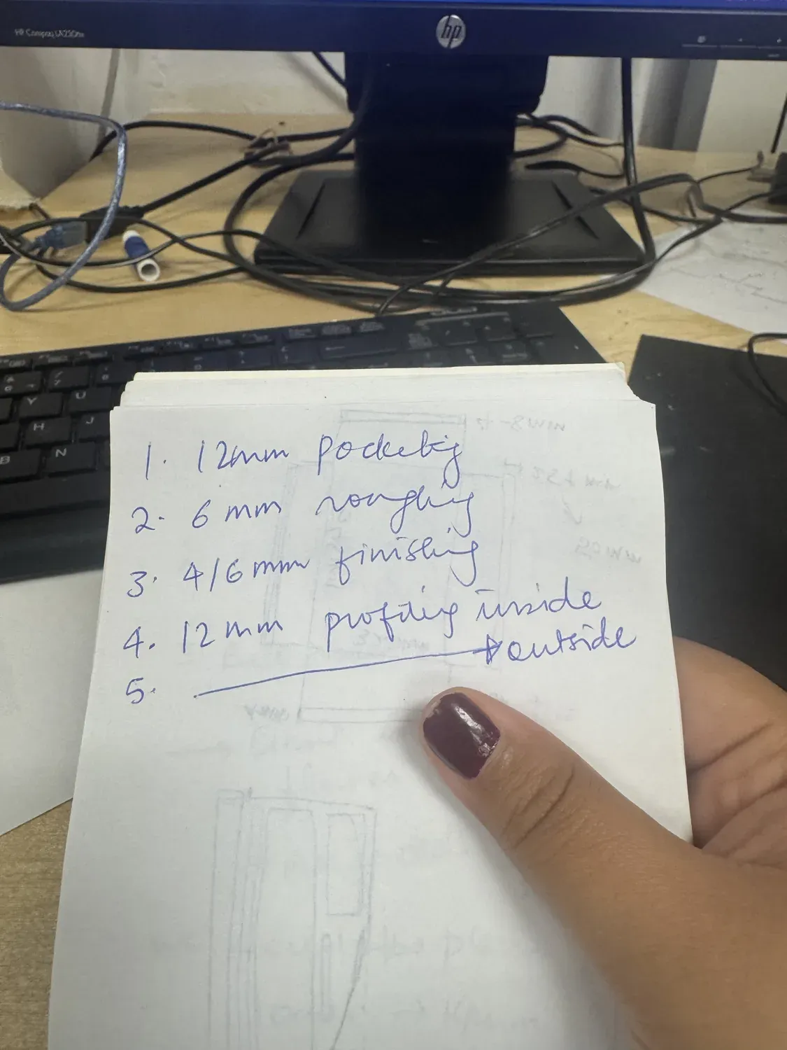
Layer thickness / spacing plan for the stack-up.
The Integration Model (CAD)
I modelled the whole assembly in Fusion as one file, with every physical part as its own body — Monitor, woodstock (the frame blank), MiniPC, acrylic, PCB, and the carved Mirrorframe. Keeping them as separate bodies in one document let me check fit, depth, and clearances between layers before cutting anything.
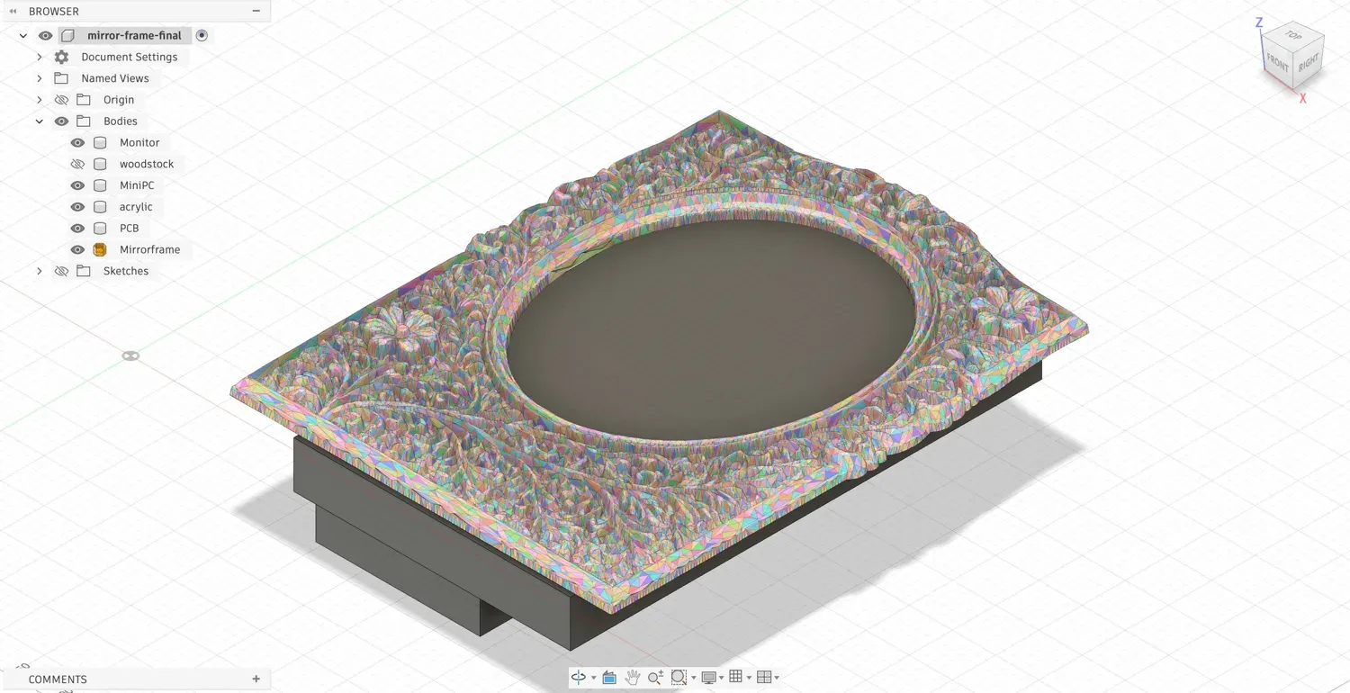
The full assembly in Fusion — the body tree (Monitor, woodstock, MiniPC, acrylic, PCB, Mirrorframe) is the integration in miniature: every subsystem in one model.
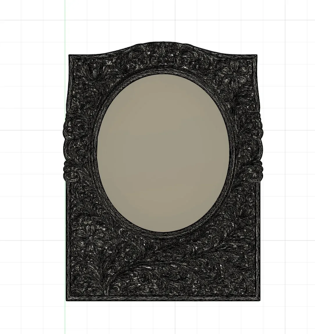
Carved frame face with the oval mirror opening.
Back face — recessed pockets locate the mini PC and PCB.
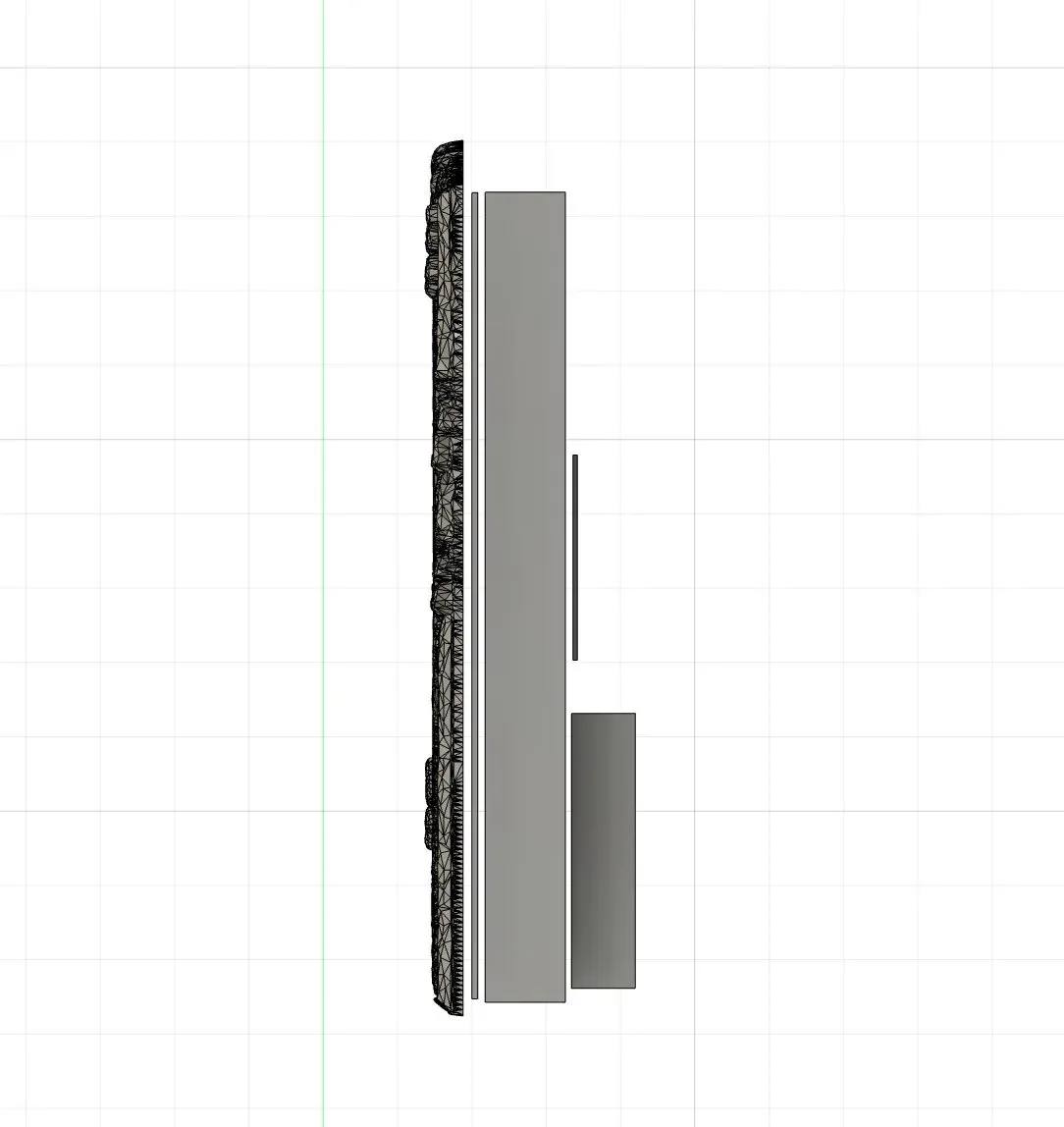
Side profile — the layer sandwich, frame to mini PC.
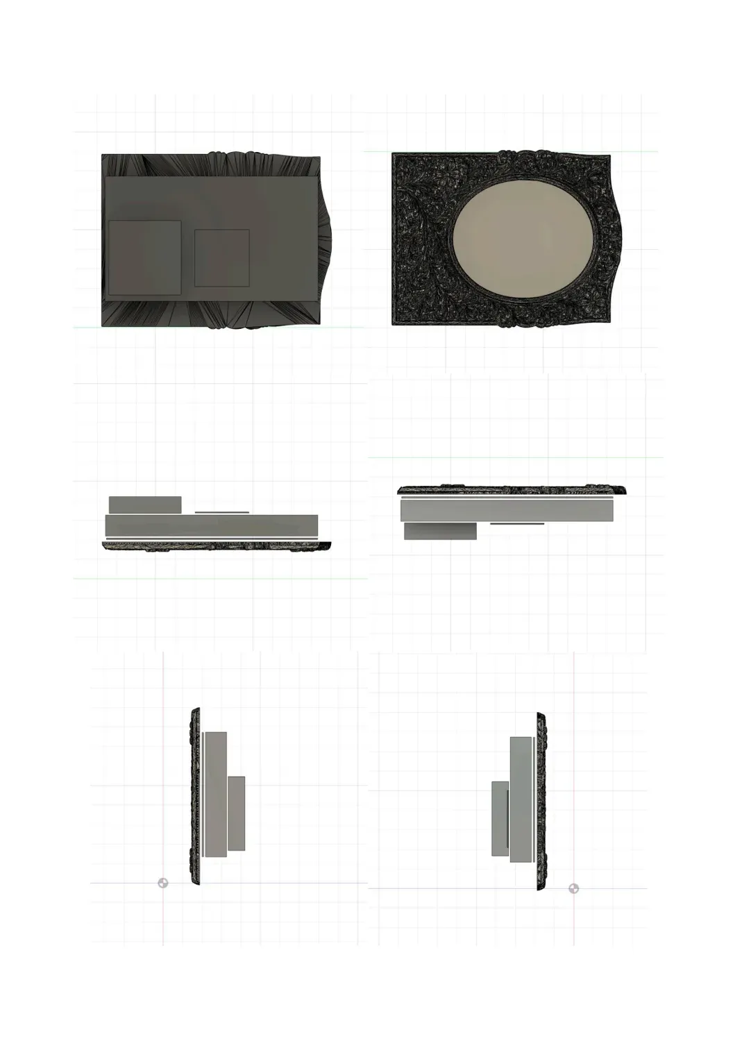
Orthographic multiview of the assembly.
Packaging & Methods
Integration came down to a set of small fabrication decisions — one per subsystem — that each turned a loose component into something fixed, protected, and serviceable.
Wood frame + glued sides
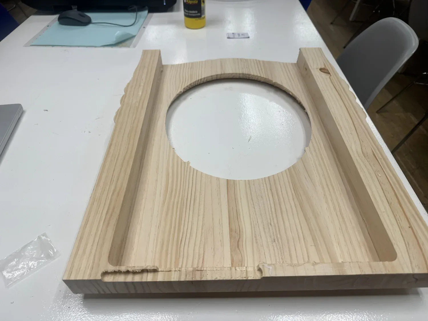
The frame and the side walls were cut to the exact same outline and glued into a box, so the sides follow the frame profile perfectly. A pocket is left open at the top, sized to the monitor, as a ventilation slot — the screen and mini PC dump heat out the top instead of cooking inside a sealed box.
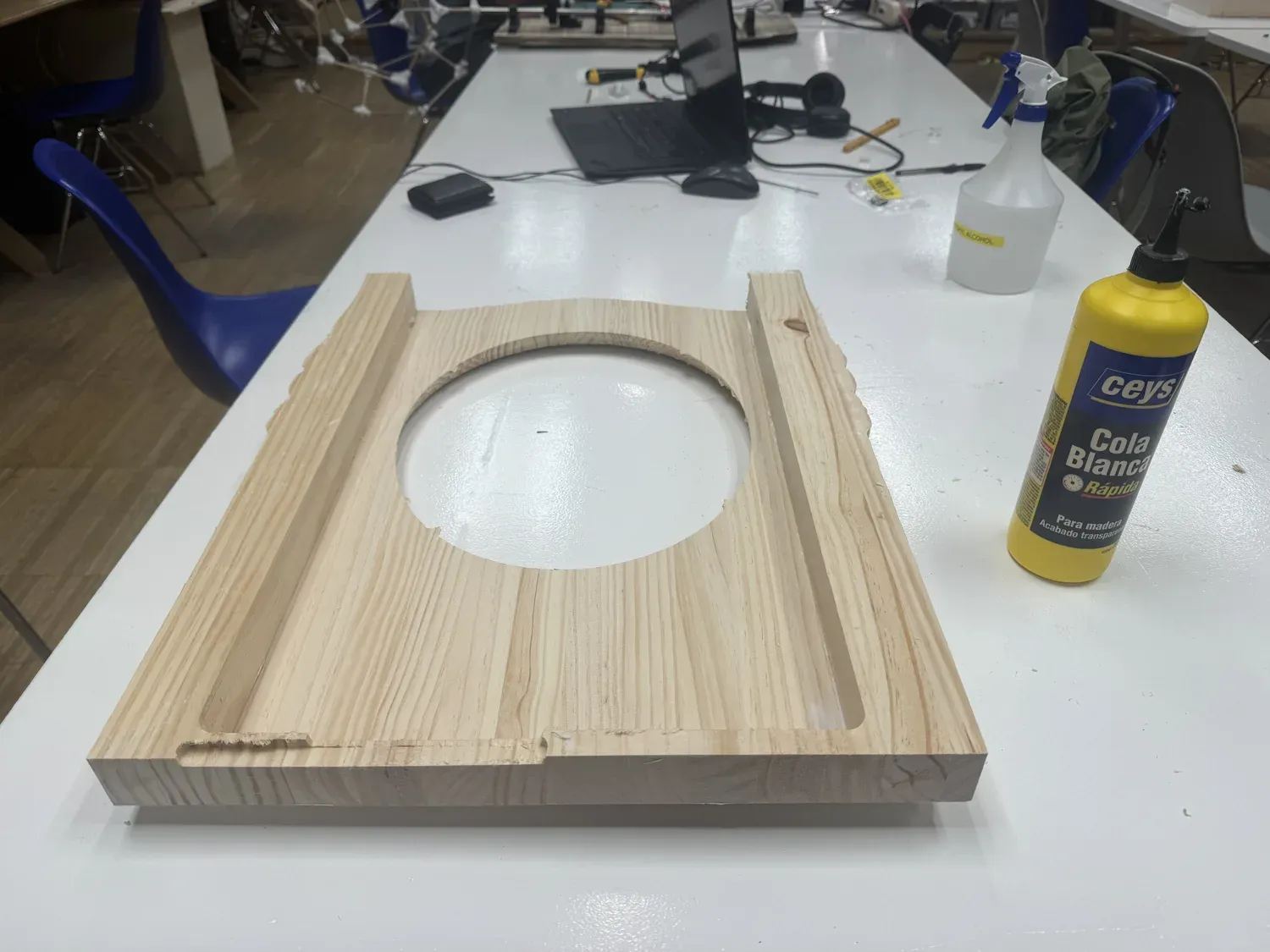
Wood frame, oval opening cut.
Glued sides + top ventilation pocket.
Frosted acrylic back panel
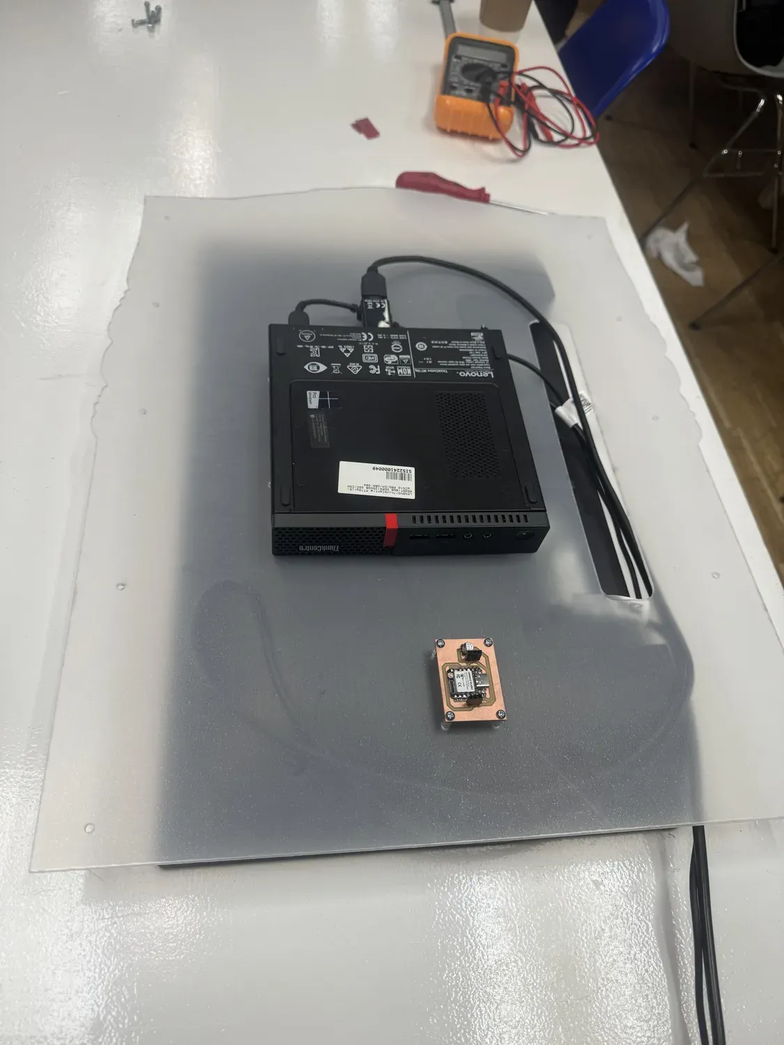
A laser-cut frosted acrylic panel forms the back of the unit. It has screw holes that fix directly into the wood, and the VESA pattern for the mini PC, so the panel is both the cover and the mounting plate for the electronics.
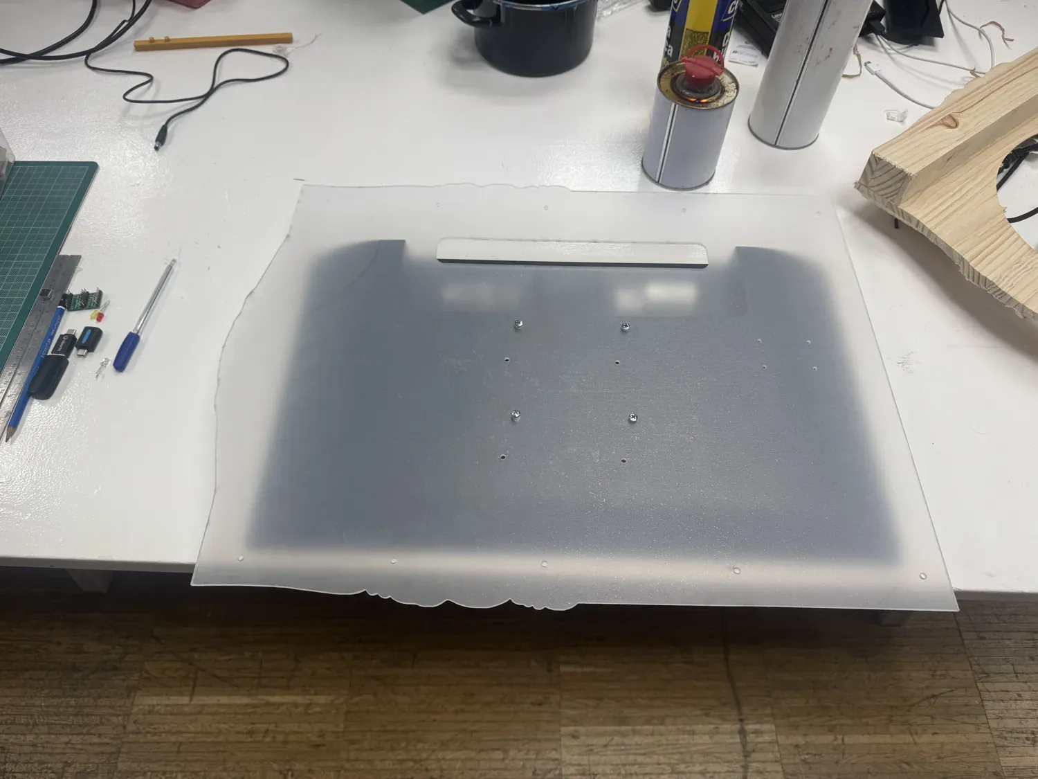
Frosted acrylic back panel, holes for screws into the wood.
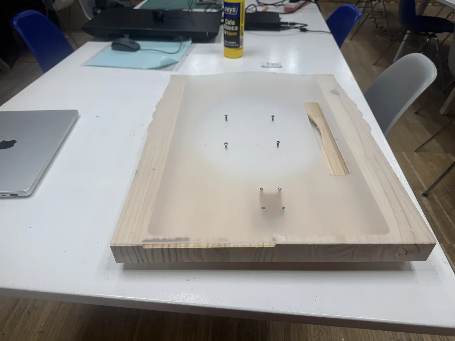
Checking the panel against the frame.
Mini PC → VESA mount
The Lenovo ThinkCentre mini PC had no mounting points where I needed them, so I drilled holes in the case to match the VESA pattern. To protect the electronics, I opened the case and taped over the screw heads on the inside so the protruding hardware couldn't scratch or snag anything internal. It then bolts to the acrylic on standoffs.
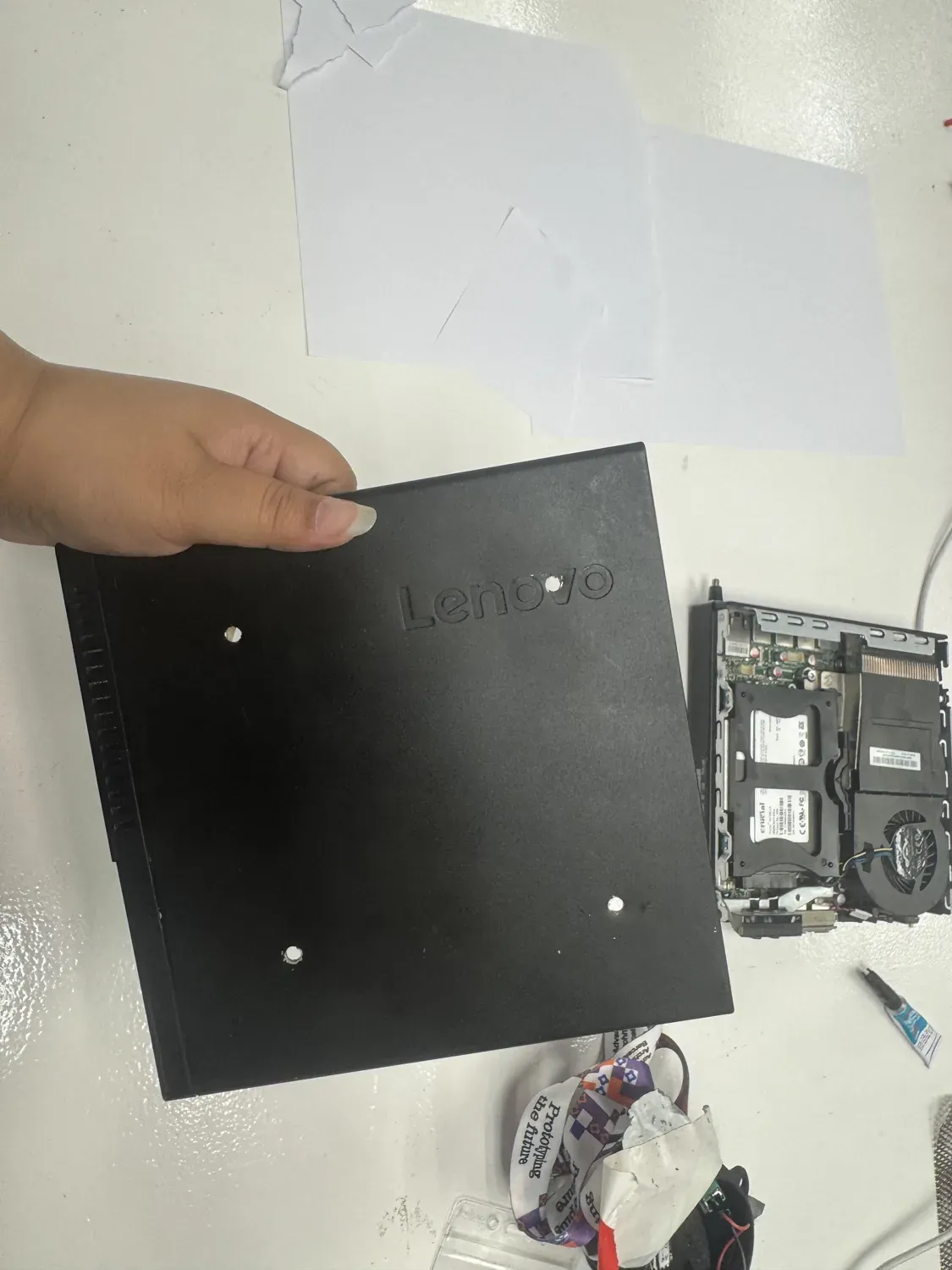
VESA holes drilled in the case.
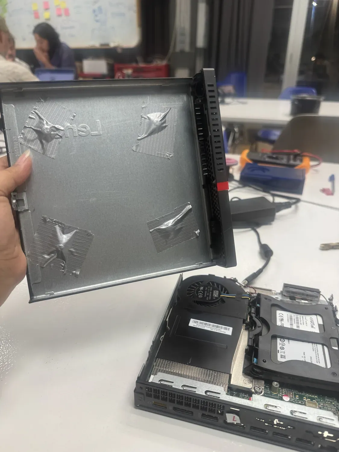
Tape over the screw heads inside — protects the internals.
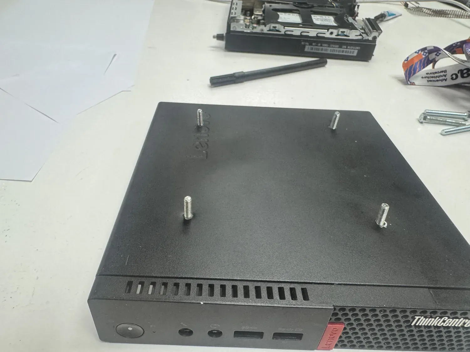
Standoffs fitted, ready to mount.
Sensor node + webcam mount
The milled copper sensor node mounts on standoffs through the acrylic, sitting behind the lower bezel. The webcam rides in a dedicated 3D-printed cradle on a curved arm that screws inside the body, holding the camera at the right angle to read the viewer through the one-way mirror. A cable organiser keeps the runs tidy so nothing is loose inside the box.
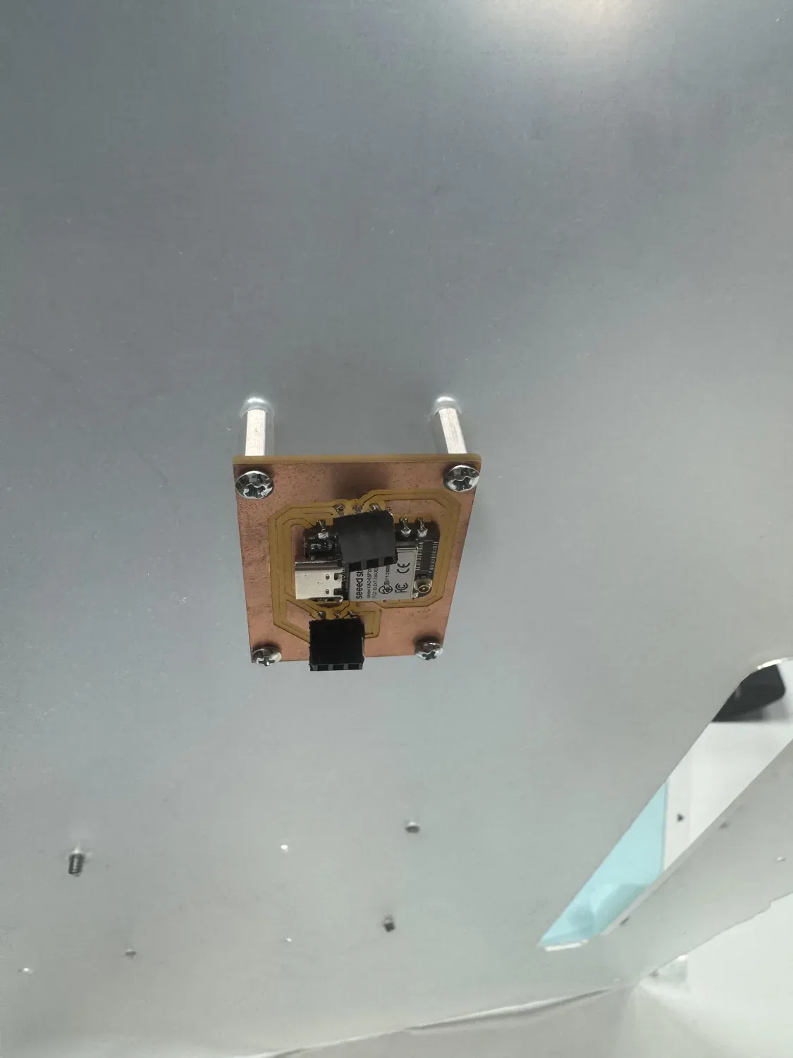
Sensor node on standoffs through the acrylic.
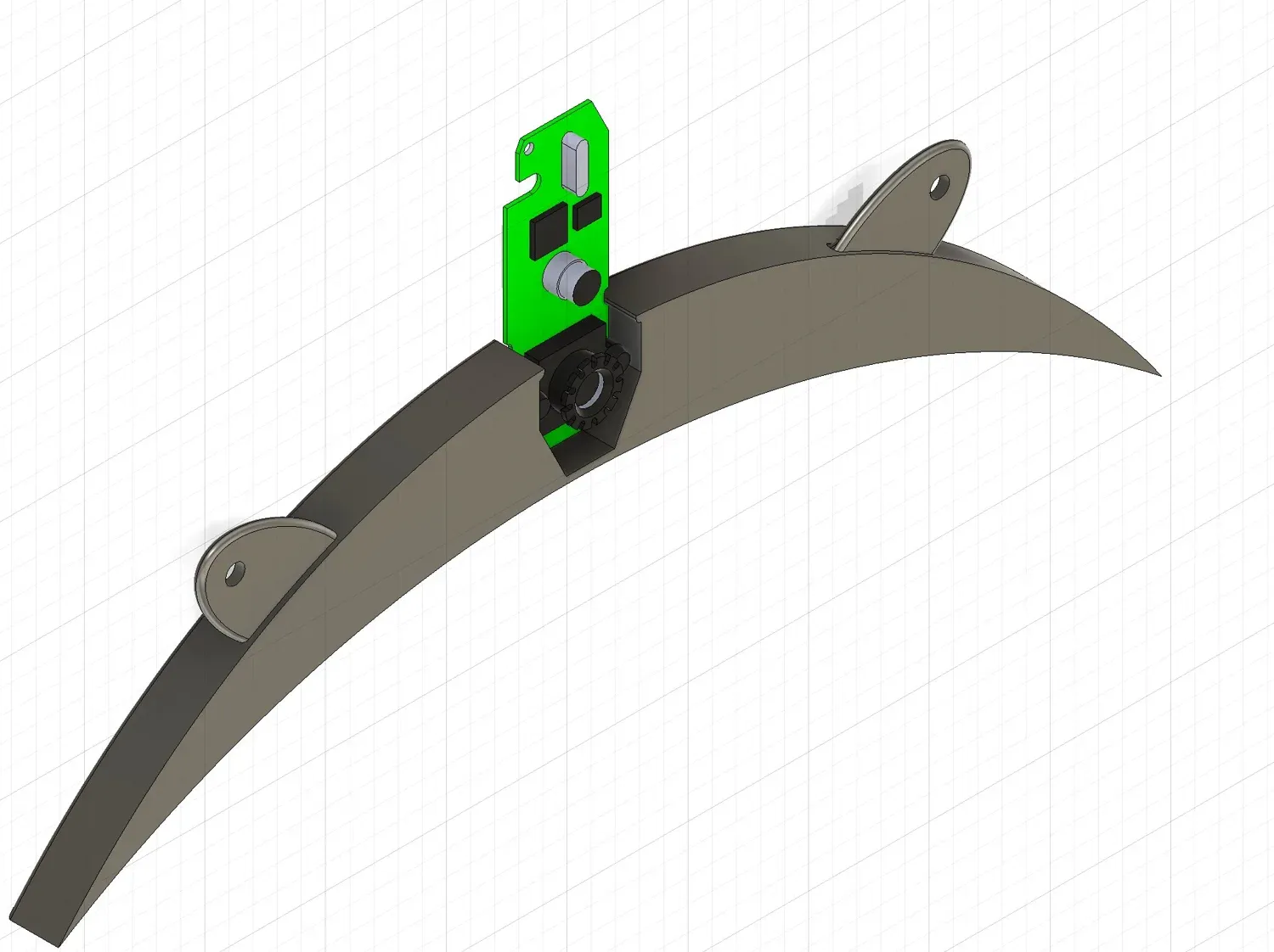
3D-printed webcam mount — curved arm, screws inside.
3D-printed box for Maya's letter
My grandmother's letter, laser-marked into acrylic, is the emotional core of the piece — so it gets its own 3D-printed housing in the lower bezel of the front, holding the acrylic letter cleanly within the assembly rather than leaving it loose. The sensor reads presence through the same front face.
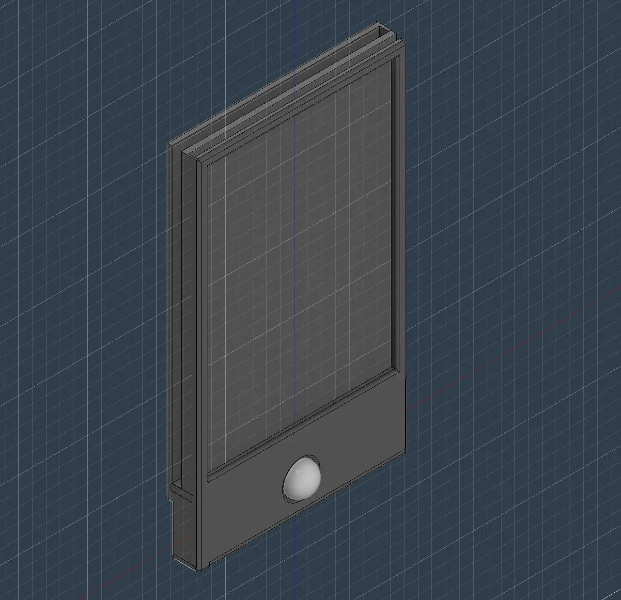
The 3D-printed lower-bezel box — houses Maya's laser-marked acrylic letter, with the sensor reading through the front face.
Laser-cut layout
The wooden enclosure pieces were nested as a single laser-cut layout, with corner gussets to hold the box square while the glue set.
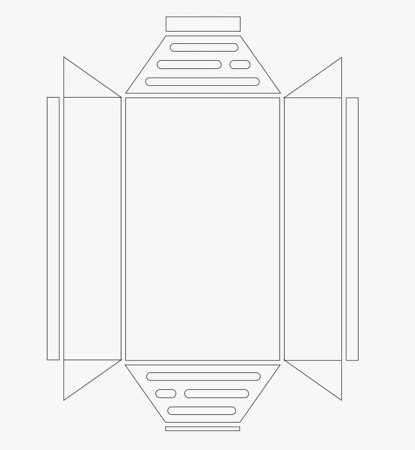
Nested enclosure panels.
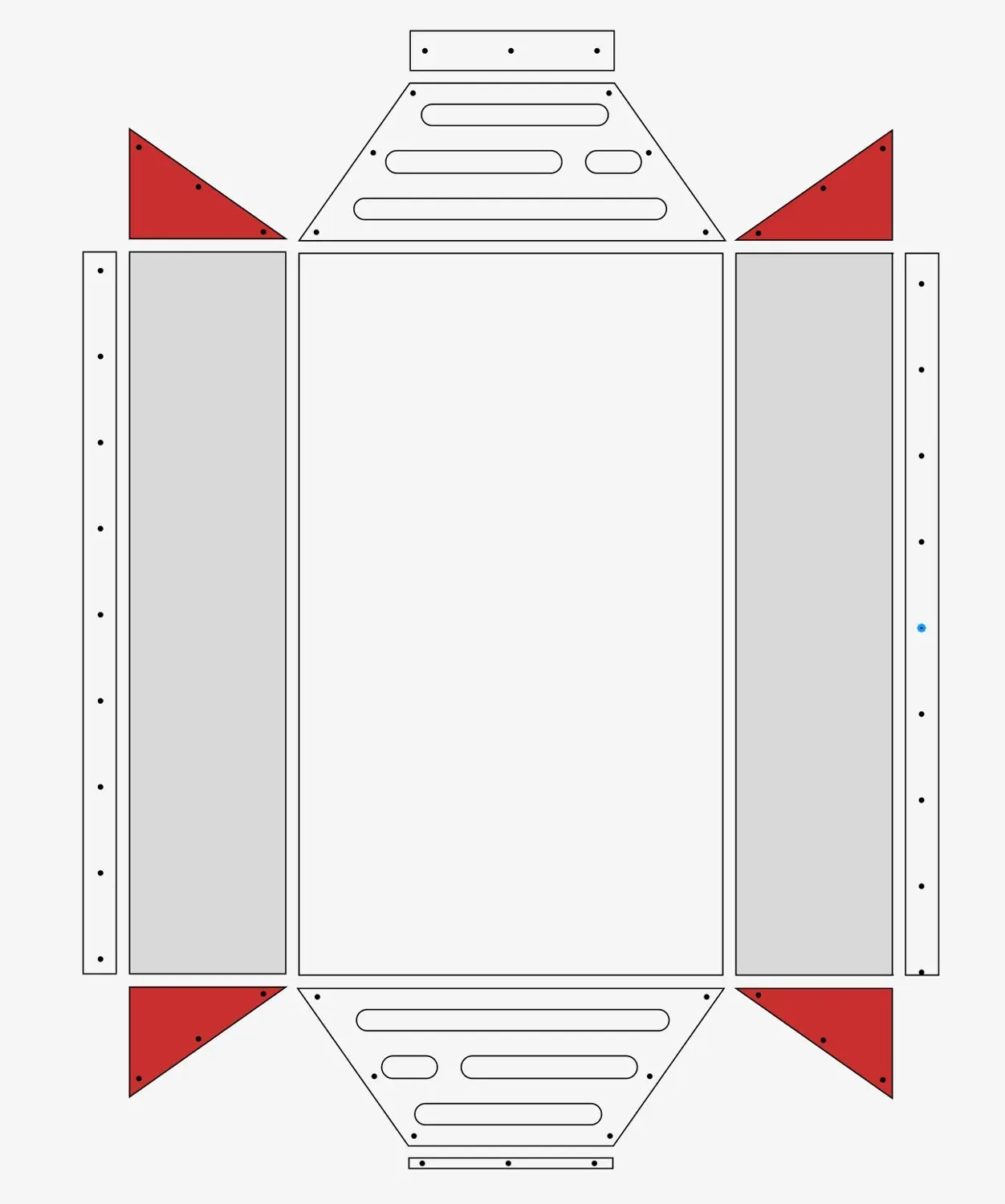
Corner gussets (red) keep the box square.
Looking Like a Finished Product
The test of integration is whether it reads as one object. From the front, the carved frame hides every seam; from the back, the frosted acrylic panel turns the electronics into a deliberate, ordered layer rather than exposed hardware. The mini PC and sensor node sit flat and fixed, cables routed, nothing rattling.
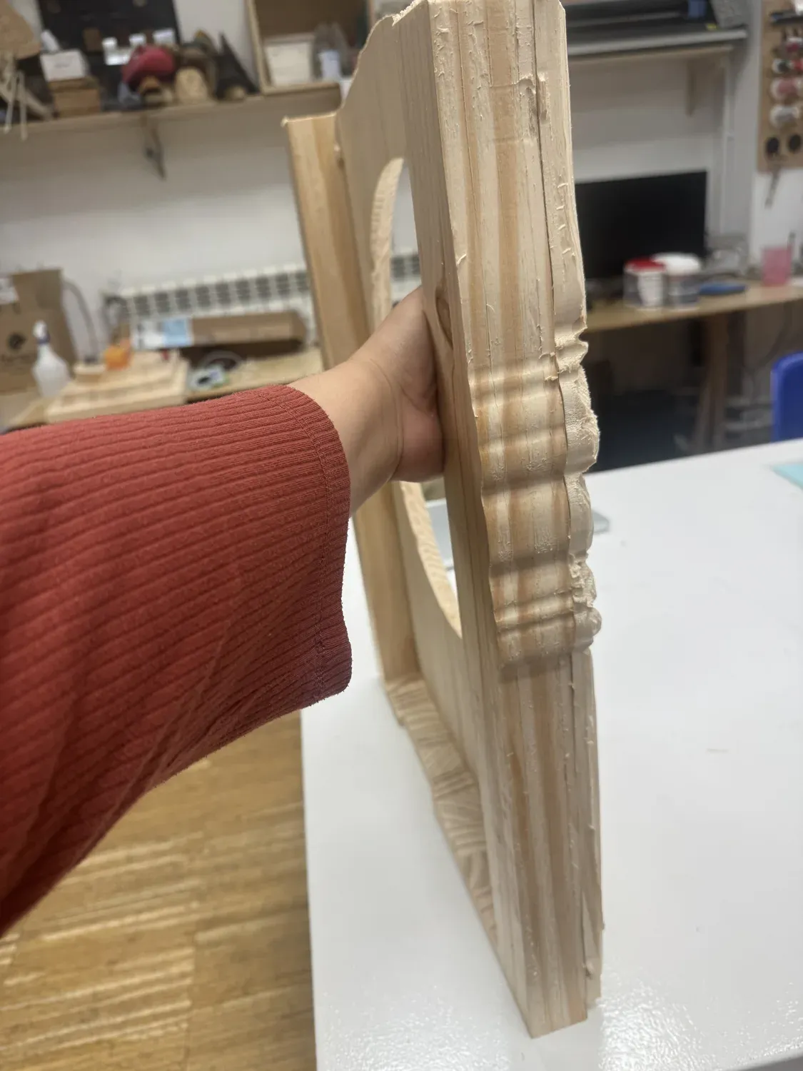
The carved molding profile — the decorative face that hides every seam.
The integrated back: one ordered layer, not loose parts.
What I Learned
1. Cut layers to one shared outline
Cutting the frame and the sides from the same outline meant they aligned automatically when glued — no fettling, no gaps. Shared geometry is the cheapest way to make parts fit.
2. Plan ventilation into the box
A sealed wooden box around a monitor and a mini PC traps heat. Leaving a monitor-sized pocket open at the top was a deliberate thermal decision, not an afterthought.
3. Make one part do two jobs
The frosted acrylic panel is both the back cover and the electronics mounting plate. Fewer parts, fewer fasteners, cleaner result.
4. Modify hardware carefully
Drilling the mini PC case was the riskiest step — taping the screw heads inside protected the electronics from the hardware I was adding. Integrate without damaging what you're integrating.