 gabriel stacey-chartrand
gabriel stacey-chartrand
gabriel stacey-chartrand
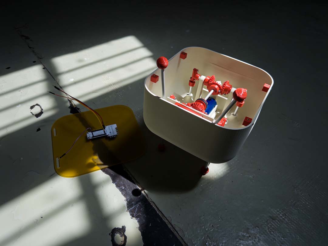
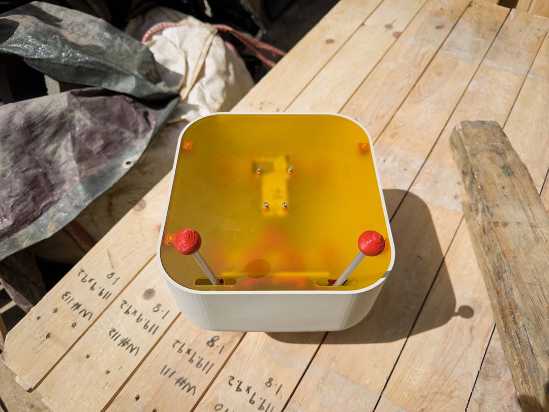
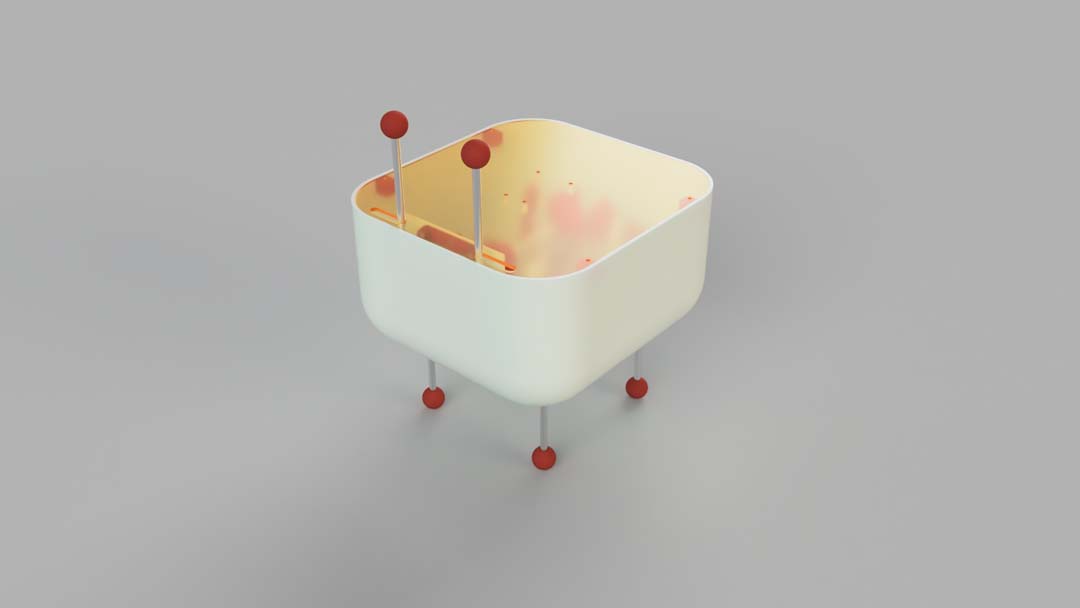
For this week our group built a machine called "Creature of the Night", a robot that dances when it's dark and stops when the lights come on. It uses a Barduino with a built-in phototransistor, a relay, and a DC motor. I designed and built the mechanical system and wrote the firmware.
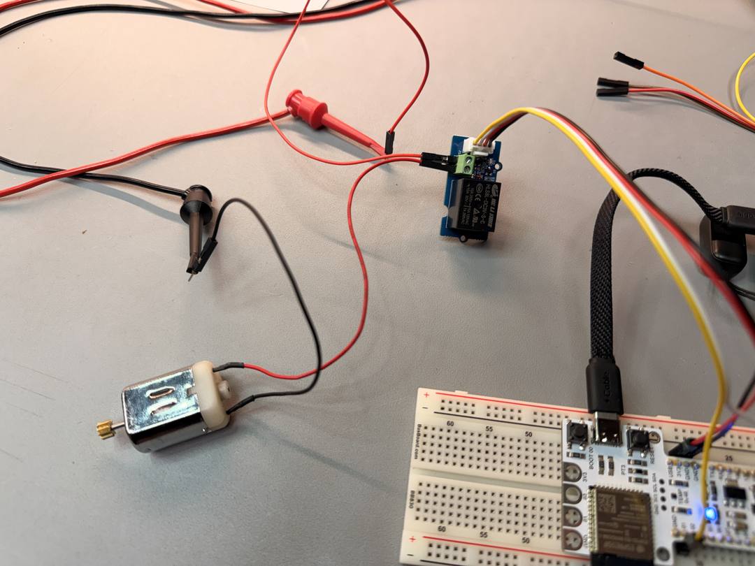
The Barduino reads its built-in phototransistor and uses a relay to switch the motor on when dark and off when light. The relay is a Seeed Studio Grove Relay v1.3, which accepts a 3.3V input signal (earlier driver modules required higher gate voltage and didn't work with the Barduino's 3.3V output).
The firmware reads the phototransistor, prints the light level to serial at 115200 baud, and drives the motor with PWM when dark.
// ============================================
//  Barduino Motor Control via Phototransistor
//  Motor ON when dark, Motor OFF when light
// ============================================

const int MOTOR_PIN        = 1;   // GPIO01 -> relay signal pin
const int PHOTOTRANSISTOR  = 3;   // GPIO03 -> built-in phototransistor

const int LIGHT_THRESHOLD  = 150; // 0-4095; adjust per environment

void setup() {
  pinMode(MOTOR_PIN, OUTPUT);
  digitalWrite(MOTOR_PIN, LOW);
  Serial.begin(115200);
}

void loop() {
  int lightLevel = analogRead(PHOTOTRANSISTOR);
  Serial.print("Light level: ");
  Serial.println(lightLevel);

  if (lightLevel > LIGHT_THRESHOLD) {
    digitalWrite(MOTOR_PIN, LOW);
    Serial.println("Light detected -> Motor OFF");
  } else {
    analogWriteFrequency(MOTOR_PIN, 20);
    analogWrite(MOTOR_PIN, 25);
    Serial.println("Dark detected -> Motor ON");
  }

  delay(100);
}I wanted the legs to go up and down rather than walk, so the robot would dance in place. I designed a crank-and-slider mechanism in Fusion 360 to convert rotation into vertical leg movement, with offset cranks so legs move at different times.
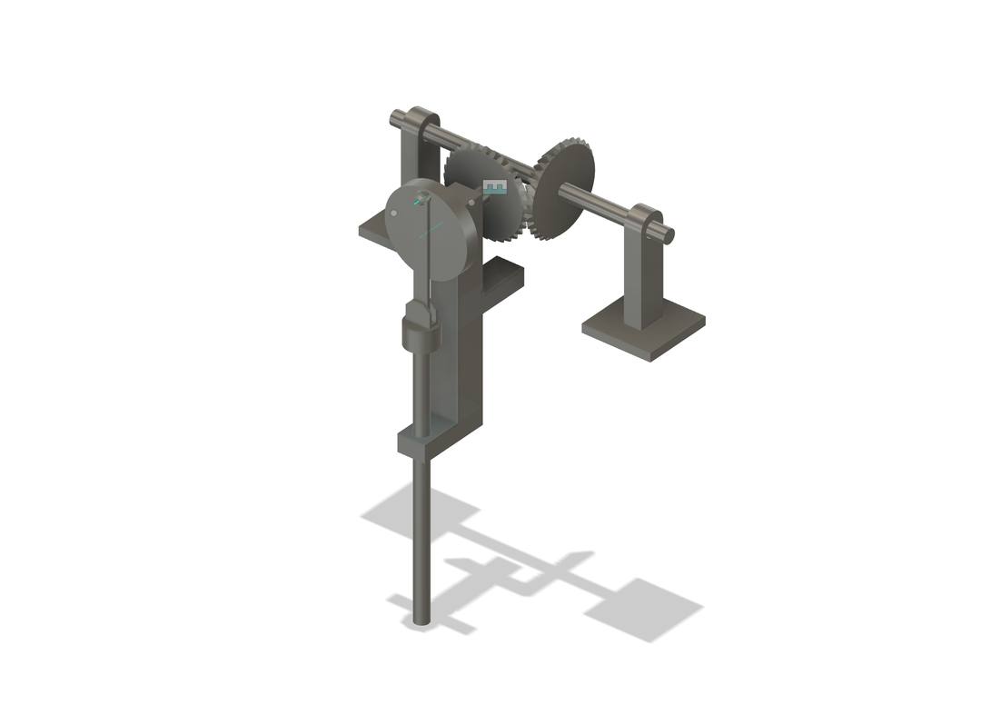
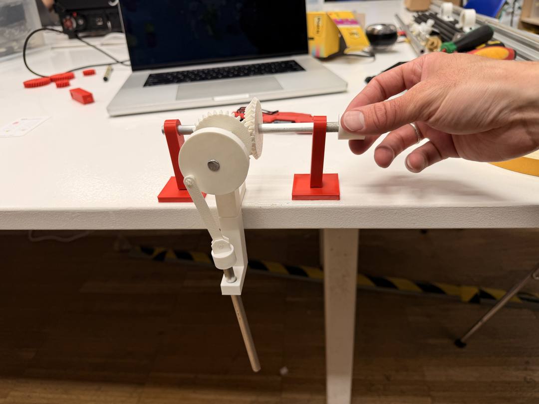
I added a secondary antenna mechanism driven from the same axle. I animated the joint relationships in Fusion to verify the motion before printing, then printed and assembled the combined leg and antenna mechanism.
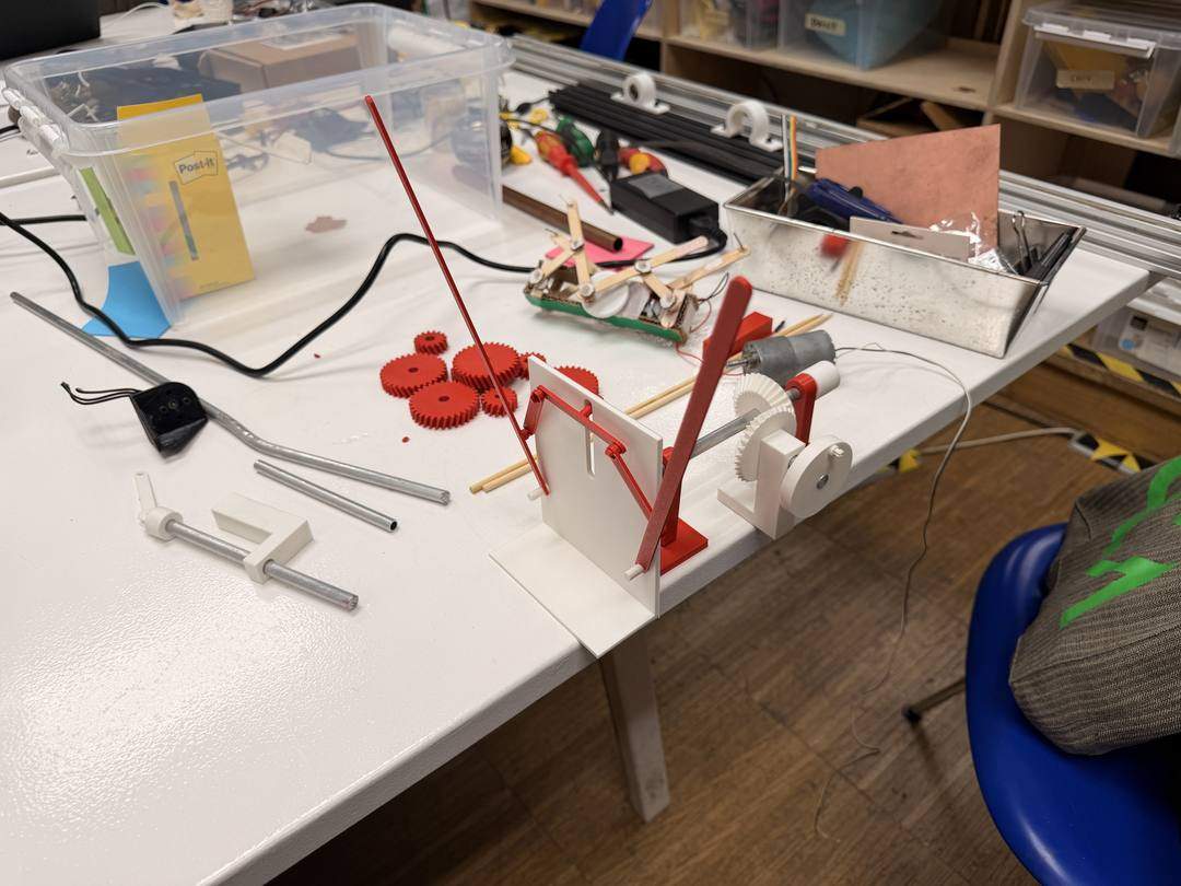
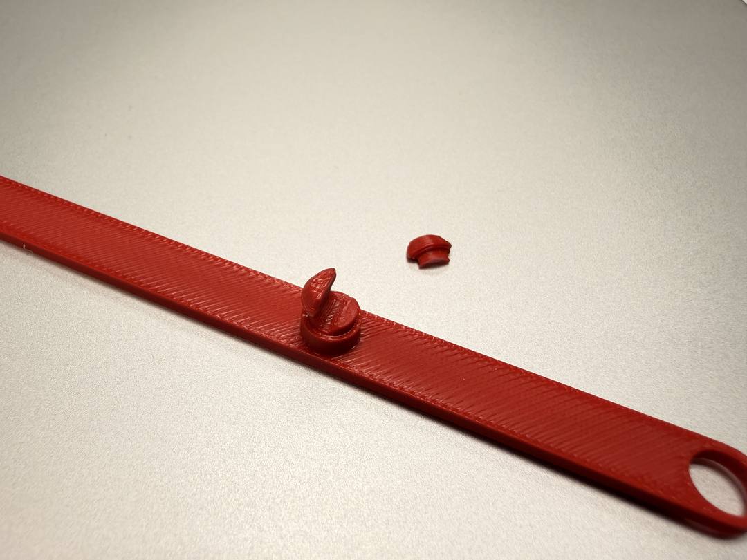
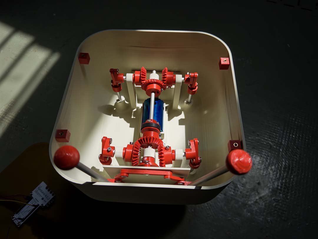
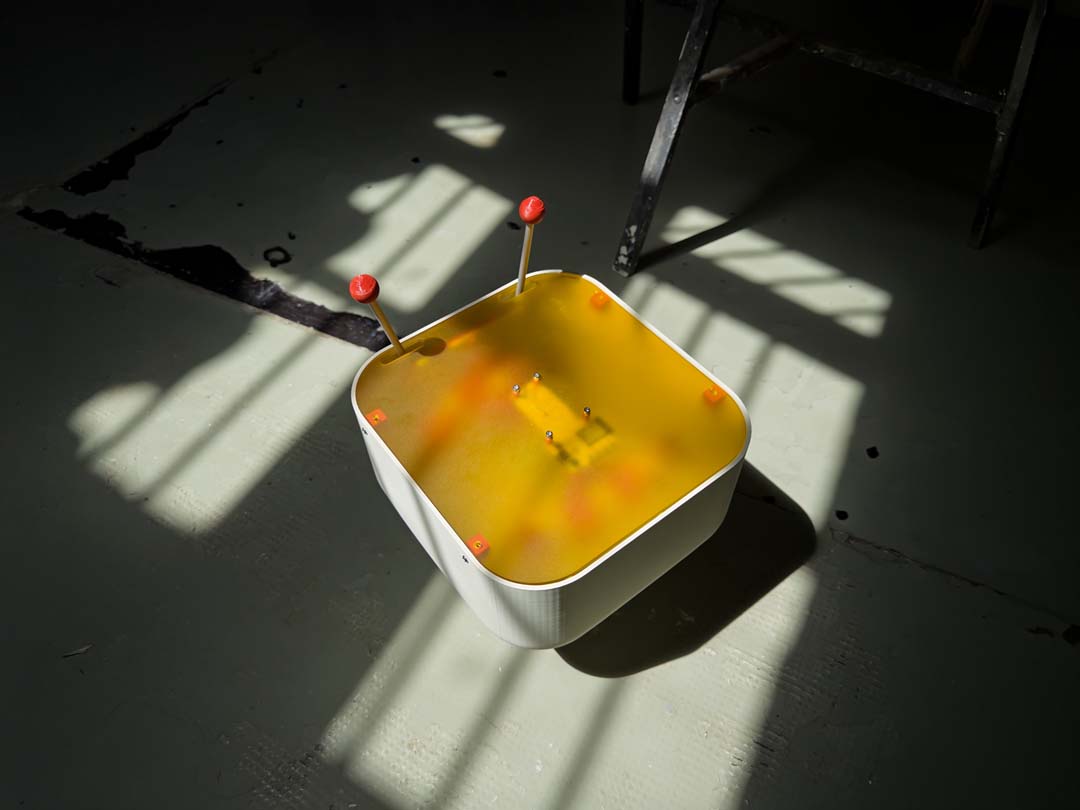
I redesigned everything from scratch in Fusion 360, based on the tested mechanisms. The body was sized just under the maximum print area of the Bambu A1/X1. The motor is geared down using bevel gears and mounted under the main axle inside the body. Aluminum rods from a local hardware store (Servei Estació) serve as axles. The Barduino sits under a laser-cut acrylic lid so the phototransistor can read ambient light while the board is enclosed.
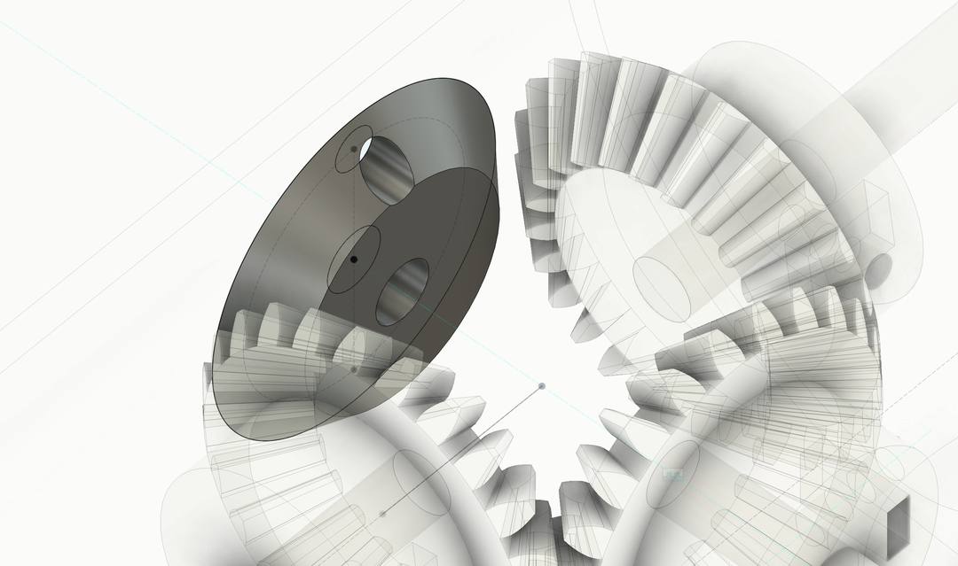
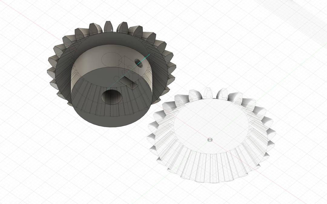
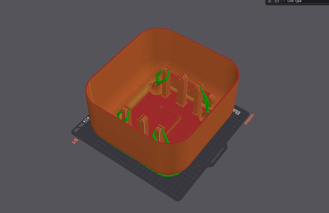
Parts printed in PLA on Bambu A1/X1 printers. The body was printed as a single piece. The sides had some delamination issues. I also forgot to add holes for the lid fixtures in the first print and had to add them in CAD and reprint.
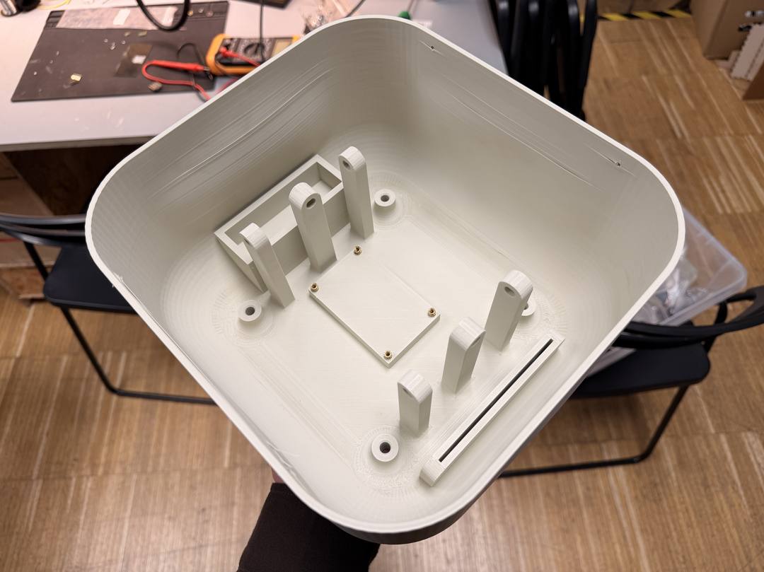
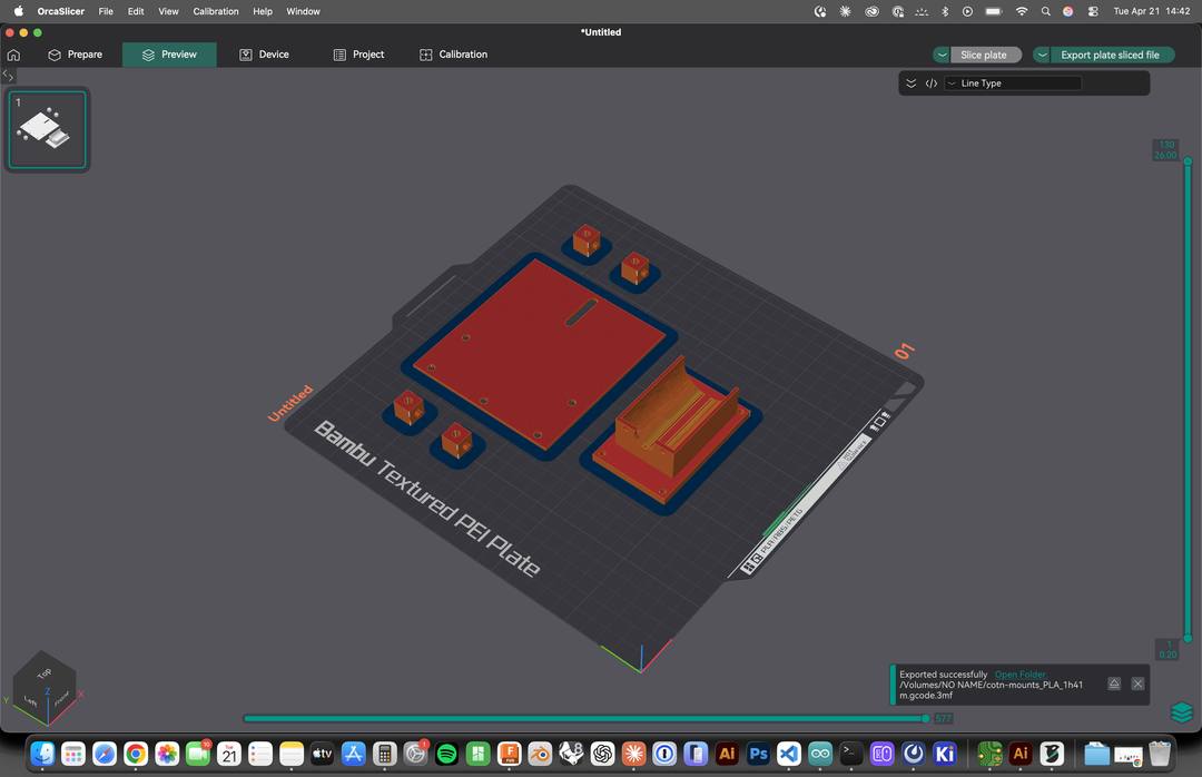
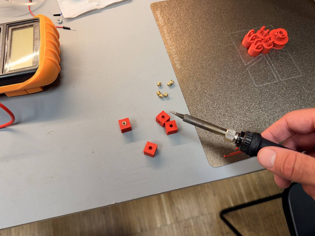
The lid was laser-cut from amber translucent acrylic so the phototransistor can read light through it. The lid mounts to the body using heat-set inserts and screws.
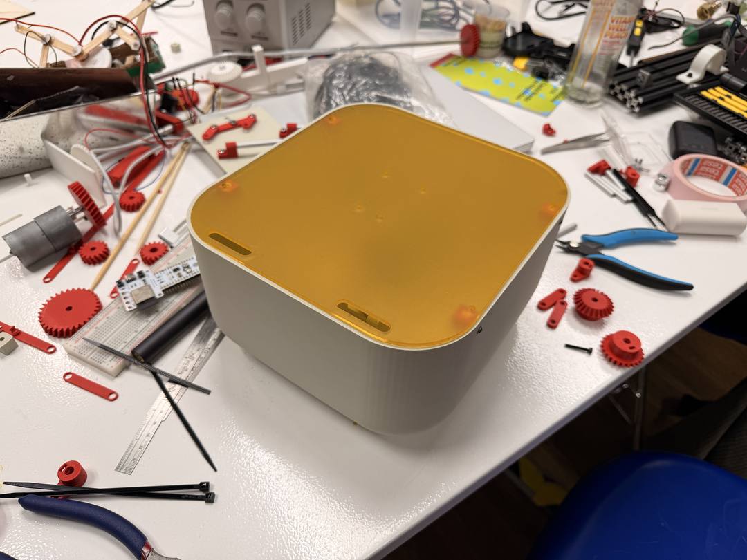
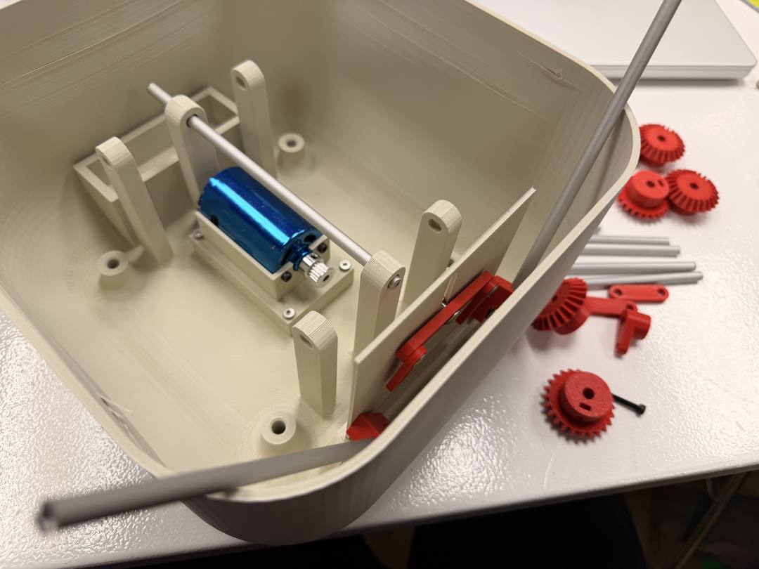
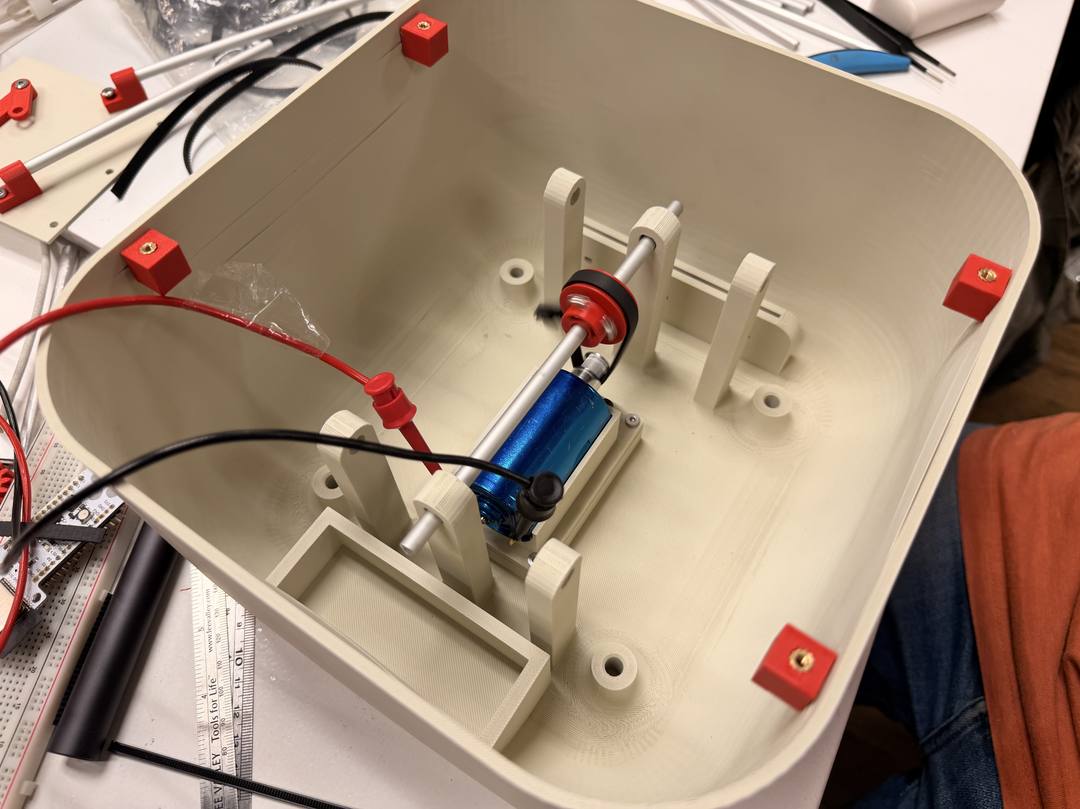
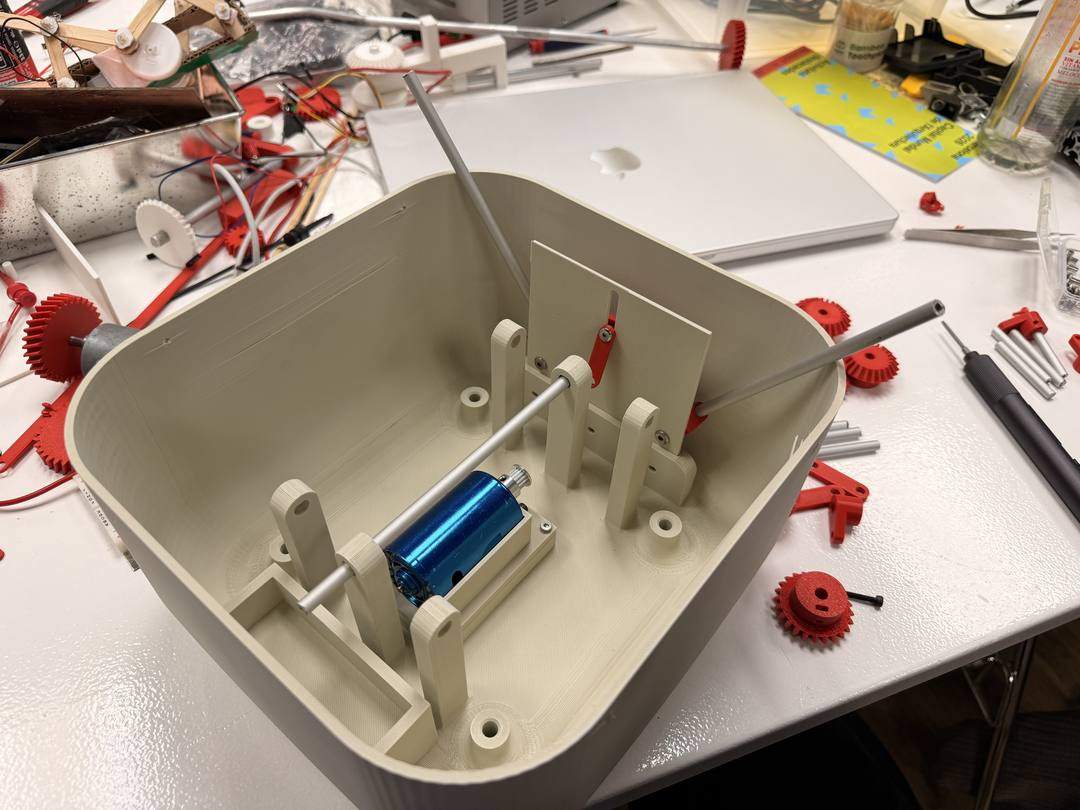
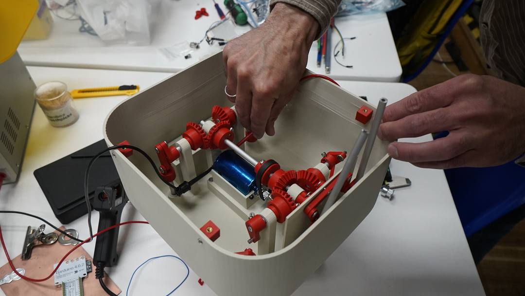
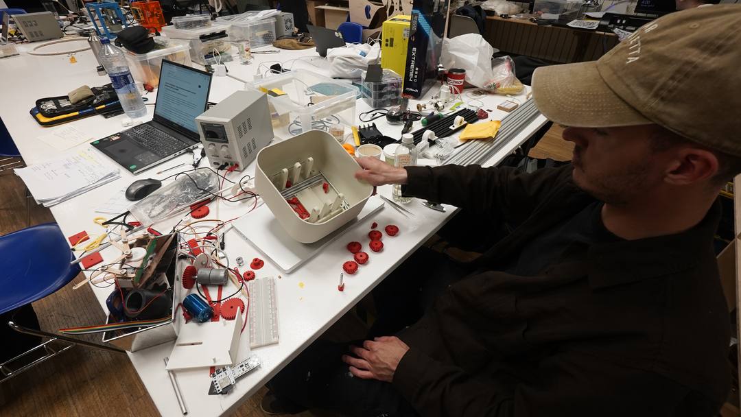
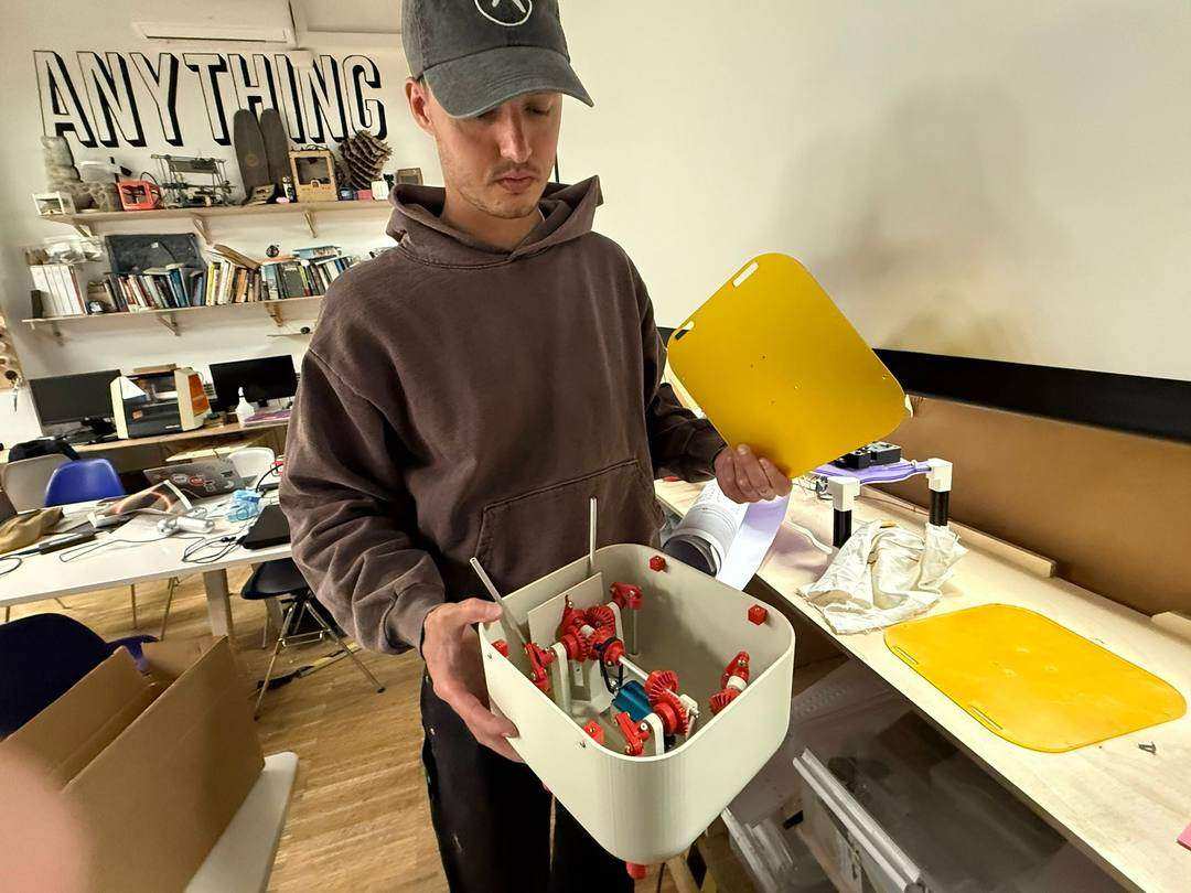
The mechanism ran but had significant issues: gears binding, too much torque from the motor, too much play on some joints and not enough on others. PWM was added to reduce motor speed and torque. The robot worked in the end but was rough. Some of the axle supports eventually snapped off.