 gabriel stacey-chartrand
gabriel stacey-chartrand
gabriel stacey-chartrand
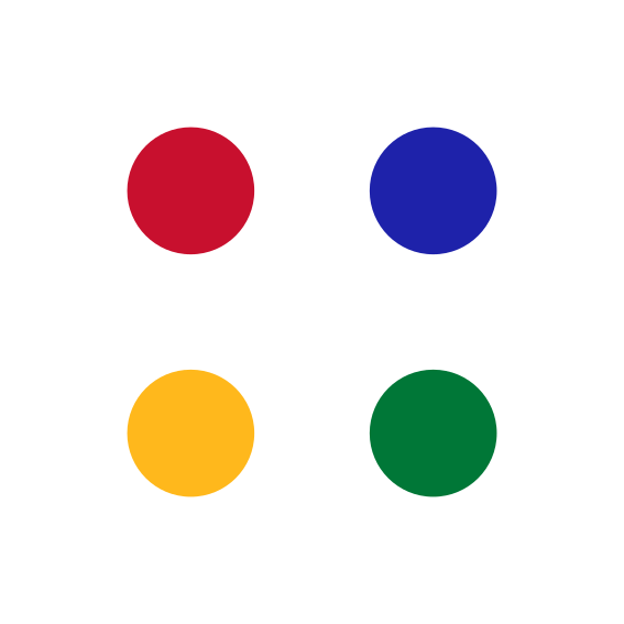
This week I worked with addressable LEDs. I started with a simple 8 pixel NeoPixel strip to get the wiring and code basics down, then moved on to a 2x2 grid of NeoPixels for my logo's four dots, first lighting it as a static logo, then adding a fade in/out.
NeoPixels and similar addressable LEDs each have a driver chip built directly into the LED package, so every pixel can be set to its own colour over a single data line. They're wired in a chain, with data in on one end and data out to the next pixel. You only need to use one data pin to write to all of them.
Both the Adafruit_NeoPixel and FastLED are great libraries that handle effects and colour addressing for you. NeoPixel is the simpler of the two: set a pixel with strip.setPixelColor() and push it out with strip.show(). FastLED works with an internal CRGB/CHSV array that you write to directly, and adds extra helpers for colour blending, palettes, and global brightness control via FastLED.show().
HSV describes a colour as hue (which colour, 0-255), saturation, and value (brightness), instead of mixing red/green/blue. This makese animation and shifting colours very easy, which can be done by simply ramping a number rather than changing RGB values.
I started with a simple 8 pixel NeoPixel strip to confirm the wiring and a basic addressable LED sketch.
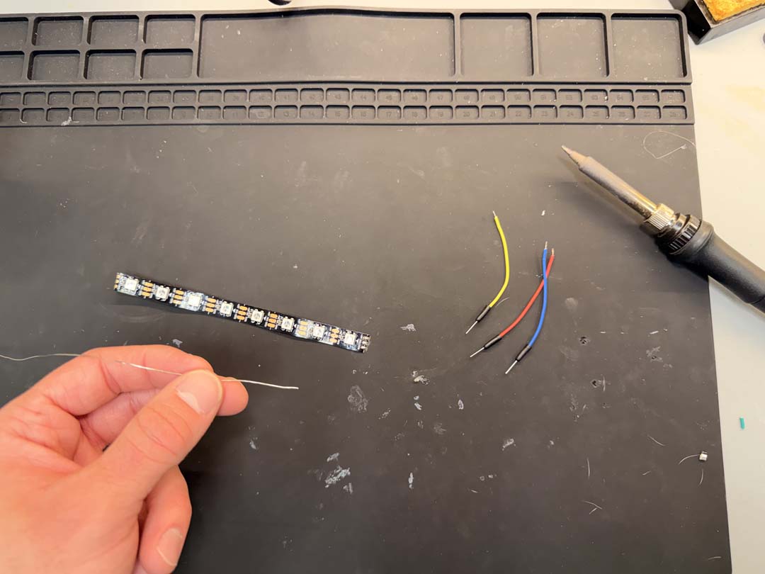
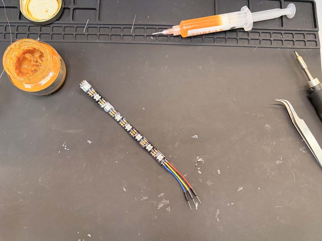
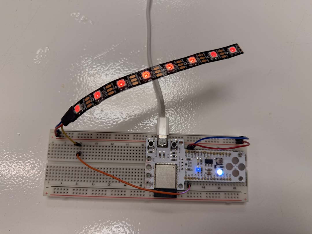
Wired up to the Barduino on a breadboard, I ran a colour wipe test, stepping through a few shades of red/orange one pixel at a time.
Download strandtest-colourwipe-test-8LEDs.ino
For the pomodoro timer watch I designed for week 08 (electronics poduction) I had wanted to embed 4 NeoPixels into the watch face. For this test, I wired them into a 2x2 grid using two strip of two.
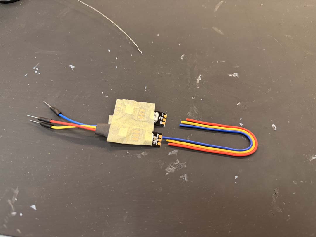
I ran a quick test with all four pixels set to the same colour, just to confirm the wiring and data chain were good.
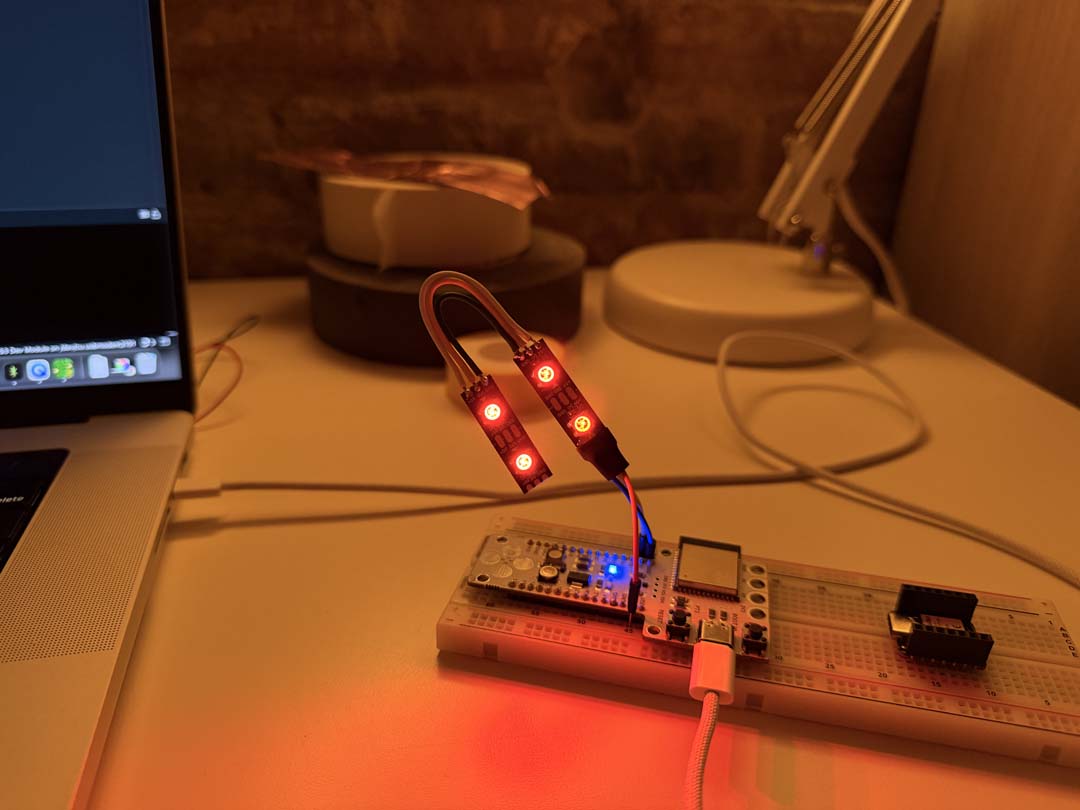
With the wiring confirmed, I mapped each of the 4 pixels to one of the dots in my logo using CHSV values, then set a static brightness.
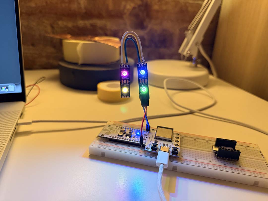
I had to adjust the CHSV values by eye until they matched the colours of my logo more closesly.
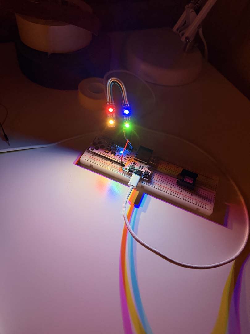
I wanted to see how these might shine through transparent PETG, for the watch face.
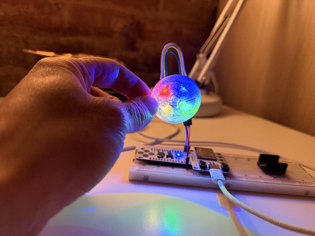
Download static-logo-neopixels.ino
Last, I took the static logo sketch and added a brightness ramp, the whole logo fades in, holds, fades back out, pauses, then repeats.
Download fade-logo-neopixels.ino
On one of my boards I used a MAX7219 display to display information for my alarm clock and pomodoro timer.
idle state: current time with dot separator blinking, ON text flashes on the screenpomodoro work state: full display used as progress bar shrinking from right to leftpomodoro paused state: full display pulsing slowly and dimmedpomodoro active state: RST text flashes on screen
  Display behaviour per state:

  Clock           HH:MM, dot separator blinking once a second
  Alarm set       alarm time, gentle pulse, 10s then back to clock
  Alarm firing    current time pulsing in/out until dismissed
  Pomodoro work   32-column bar shrinking right to left, dims when paused
  Pomodoro break  full display pulsing slowly, dims when paused
The MAX7219 communicates over SPI, which is a synchronous serial protocol. Four modules are chained together, data flows in one end and out the other, so the microcontroller only needs three signal lines to drive all 32 columns at once. With power, that's five wires total:
There's no data line back to the microcontroller. The MAX7219 is write-only. Each module passes unaddressed data through to the next, so you can daisy-chain as many as you want on the same three pins.
The firmware uses MD_MAX72XX by MajicDesigns, which handles the low-level SPI framing and gives you column-level write access via mx.setColumn(col, byte). The display is 8 rows tall, so each column is one byte, one bit per row.
MD_MAX72XX ships with a built-in font, but I asked Claude to write a custom one to have full control over the pixel shapes. Each character is defined as 5 bytes, one per column, with each bit representing a row from top to bottom. For example the digit 0:
{ 0x3E, 0x45, 0x49, 0x51, 0x3E }
// col 0   col 1   col 2   col 3   col 4
// 0111110 1000101 1001001 1010001 0111110
The drawText() function takes a string, looks up each character in the font table, and writes its 5 columns to the display centred in the 32-column space. The FC16_HW hardware variant mirrors the column order, so the string is iterated in reverse to compensate. Intensity is passed in as a parameter (0–15) so the same function handles both normal and pulsing states.
For the pomodoro progress bar there's no text involved. drawBar() just fills a number of columns from the right with 0xFF (all 8 rows lit) and leaves the rest as 0x00. The count of lit columns shrinks over time, giving the bar-draining effect.