
Portable 3-Point Lighting System
This project aims to create a portable, modular 3-point lighting system designed for small-scale object and product photography. The goal is to make the system accessible with little to no learning curve, featuring adjustable brightness, color temperature, and compact storage.
Concept and Inspiration
I'm a film major, but somehow I find myself stuck in the Fab Lab for hours and hours doing things that have no direct correlation to film at all. Sometimes I wonder if I’m even in the right school. Regardless, I chose to push full steam ahead with my Fab Academy final project, combining my interest and love for filmmaking with my curiosity about technology.
I decided to create a three-point automatic lighting system, inspired by the new moving and gyroscopic tripods I saw in Instagram reels produced by the company Edelkrone. I was really inspired by their work and wanted to build a modular lighting rig that could move horizontally and diagonally using three lights, because in filmmaking, a 3-point lighting setup is essential.
• • • 3D Modeling in Fusion 360
I began my project in Fusion 360 by modeling a series of parts that I would eventually 3D print. I focused on modularity, using 2020 speed rail as the foundation because of its compatibility with countless accessories and its standardized sizing. This allowed me to reference and remix many existing community designs from online databases.
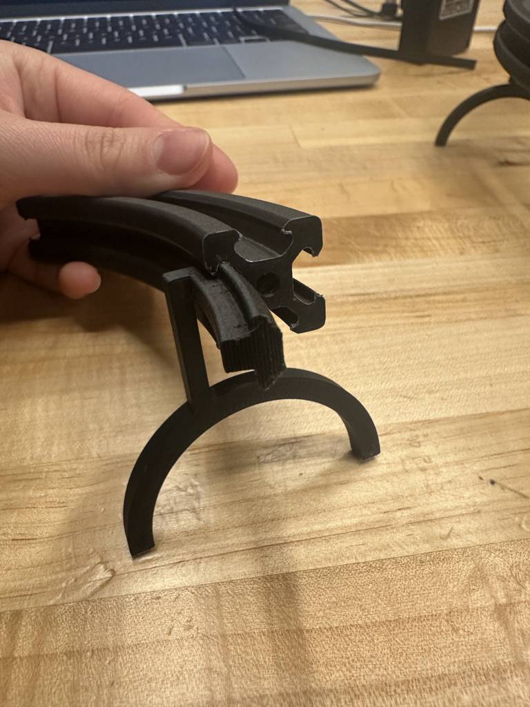
My core rail structure was a curved 20x20 profile. I designed it in eighth-circle segments, so that two of these segments would form a quarter-circle curve. This approach made printing and assembly easier. I also modeled an insertable V-slot leg stand that would support the structure from within the circle, ensuring stability without interfering with the dolly that would ride around the outside edge of the rail.
Each component was designed to print cleanly with minimal support, and I refined the geometries to be mechanically sound while still printable using standard PLA filament. These parts formed the structural backbone of the system.
• • • 3D Printing and Mechanical Assembly
Curved Parts and Leg Stand
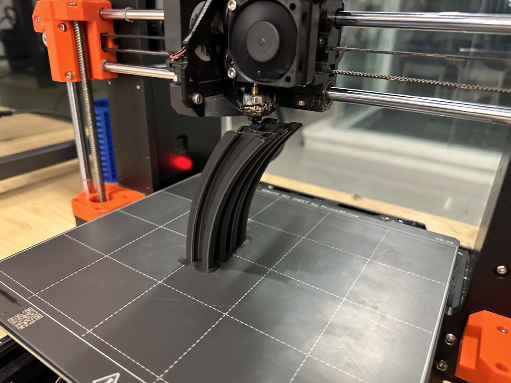
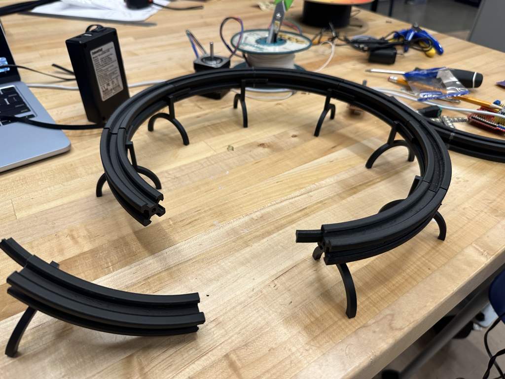
The first parts I printed were the curved 20x20 rail segments. I printed them in eighth-circle sections using black PANDACHROME PLA filament and then sanded the edges for smooth mating surfaces. I used hot glue to join two segments at a time, forming complete quarter-circle arms. These were later joined to form the complete circular track.
I also printed the V-slot leg stand insert using charcoal cotton mat PLA filament. This part sits inside the rail and provides stable vertical support. I made sure it didn’t interfere with the dolly's travel around the outer edge of the curve.
Small Adapter and Dolly Setup
Next, I printed a small angled adapter that helped position the curved 2020 rail at a better angle. This adapter allowed me to maintain a consistent platform height without redesigning the full rail system.
Once the structure was set up, I worked on installing the dolly system. I used two purchased dollies and found a third one in the lab. These dollies ride along the curved rail and were the foundation for my moving light modules. I attached a timing belt to each dolly by threading it through the mounting pins. I also drilled through-holes in the curved rail segments to guide the belt path around the system.
Belt Routing and Pulley Mount
After positioning the belt, I designed and installed a motor-side pulley mount. This component held two timing belt idlers with integrated ball bearings, allowing for smooth bidirectional tensioning. I looped the belt all the way through the system and used super glue to secure the ends together. This part was extremely difficult and messy. I ended up with super glue on my hands, pants, and even my laptop.
Stepper Motor Integration
Finally, I printed and attached a stepper motor mount designed to slot directly into the 2020 rail. The stepper motor interfaced with the belt and allowed me to control the movement of the dolly around the track. I also printed a snap-on cover to protect the motor and gear assembly while keeping the timing belt in place and maintaining tension.
• • • Light Box Design and NeoPixel Integration
Designing and Printing the Light Box
I designed a V-slot-compatible component that mounted to the inner curved portion of the rail and held a custom light box. I left a hole in the back of each box so LED wiring could pass through and daisy-chain from one light to the next. This part of the design took a lot of iteration, since I had to finalize the rail structure before I could properly size the light boxes.
To get a clean print surface, I printed each light box upside down. I also labeled the top with "Light Loop" as part of the design. After testing, I realized the original box was too small and the walls were too thick. I also hadn’t accounted for wire spillage on both sides of the light, so I redesigned and reprinted the boxes with more internal clearance.
Discovering the RGBW NeoPixels
Once the structure was ready, I began wiring the lights. At first, I wrote code assuming the NeoPixels were standard RGB strips. Later, my professor pointed out that these were actually RGBW strips—each LED had a dedicated white diode alongside the RGB channels, visible as a half-yellow, half-white segment on the LED surface.
This discovery changed everything. Since I could now produce white light directly, I no longer had to combine red, green, and blue at full brightness, which reduced the total current draw and simplified the circuit logic.
Power Supply Challenges
Each NeoPixel draws about 60 milliamps, and I planned to run 20 to 30 LEDs—meaning I needed roughly 2 amps of current. My battery pack could supply exactly 2 amps, but the Seeed XIAO ESP32C3 has a built-in current limiter that caps the onboard output at 800 milliamps. I wouldn’t be able to run the LEDs through the board directly.
To solve this, I spliced a USB cable and wired it directly to the 5-volt output of my battery pack, bypassing the ESP32C3 for power. I then ran a separate signal wire from a digital pin on the microcontroller to control the LEDs.
USB Splicing and Fast Charging
The battery pack I used was a dual-output 12-volt and 5-volt system. Inside the USB cable I spliced, I found four wires: red, black, green, and white. I connected red to power and black to ground, then twisted the green and white wires together. This helped activate fast charging mode, which allows the battery to provide more power if the cable supports it.
Soldering the LED Chain
During assembly, I had a tough time soldering the NeoPixels. My hands kept bumping the small components, which melted the front face of a few LEDs. That was a big problem, since NeoPixels communicate in sequence. If one LED is damaged, the rest of the chain doesn’t know where it starts or ends. I had to go back and carefully re-solder several joints, making sure all pads were clean and no data pins were broken or bridged.
Final Wiring and Fold Logic
I also had to think through the wiring layout in a physical sense. I wanted the LED strips to fold in half between the light boxes, so I had to visualize the entire circuit folding before planning the wire lengths and connections. Once I worked out that logic, things moved quickly. I measured the distance between each light and cut wire lengths to match, soldering everything together with the new light box design.
With the light boxes finalized, the power issue solved, and the circuit fully assembled, I was finally able to run all three light modules with full RGBW control—stable, bright, and efficient.
Stepper Motor Code Challenge
One of the final challenges was getting the stepper motor to work properly. After several debugging attempts, I finally remembered that when programming the Seeed XIAO ESP32C3, you must prefix pin numbers with D. I had forgotten this in an earlier project, and it caused issues that are now resolved.
With all the parts, code, and design finally working in harmony, my modular, automated 3-point lighting system came to life.
| Item | Quantity Needed | Cost |
|---|---|---|
| 2020 Profile X-axis Synchronous Belt Straighten Tensioner | 2 | $7.99 |
| QWORK Small V-Wheel Plate, 2 Pack V-Slot Gantry Rod Plate with Wheel | 1 | $13.97 |
| Talentcell Rechargeable 12V 3000mAh Lithium ion Battery Pack | 1 | $22.79 |
| PANDACHROME Matte Charcoal Black PLA Filament | 1 spool | (lab) |
| PANDACHROME Matte Cotton White PLA Filament | 1 spool | (lab) |
| Copper PCB Board | 1 | (lab) |
| LONGRUNNER 17HD48002H-22B Stepper Motor | 1 | (lab) |
| Polulu Stepper Motor Driver | 1 | (lab) |
| Seeed XIAO ESP32C3 | 1 | (lab) |
| NeoPixel RGBW LEDs | 30 | (lab) |
| ⅛" Acrylic Sheet | 1 | (lab) |
| Black, Red, and White Wire | Varies | (lab) |
| Bread Board Cables | Several | (lab) |
| Total (Purchased) | $52.74 | |