11. Networking and Communications
This week I used Ki Cad, Mods, and the Roland milling machine to make my circuit boards and made my two Xiao ESP2040 boards communicate to be able to play a game.
Research
As a kid I remember playing very simple games with my two kid hands and my opponents' sticky fingers. We would throw down an index, ring, or fat thumb and then cheer when we won through some weird arbitrary winning thing that somehow always ended up with me as the loser. To reclaim this, I have decided to make and program two boards that will communicate with each other and be able to play a simple game of Rock, Paper, Scissors. To come to this idea I thought of the games I played as a kid that had simple winning conditions and only 2 players. This thinking was stimulated by the constraint of wanting to only use two boards. I thought of Chopsticks, but there would be too many rules and logic to figure out with the winning conditions. Blackjack, High Card Low Card, Heads Tails. All those other games had a logical problem that made Rock Paper Scissors (RPS) the game of choice. I first drafted out a list of rules and an a very rough game design.
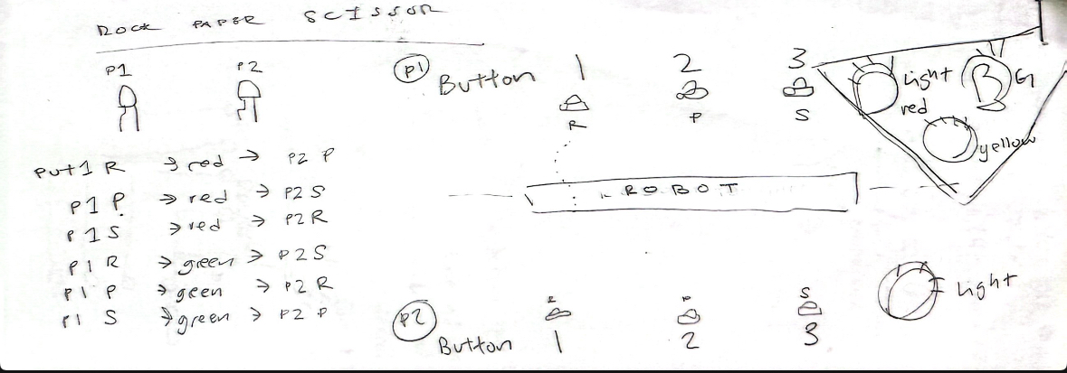
Once I started drafting my project, I realized that based on the logic I created, I would need three LEDs and three buttons for each player. Each LED would light up to indicate the result of the round for the respective player. For example, if Player 1 chooses Rock and Player 2 chooses Paper, the red LED on Player 1’s board would light up (to show they lost), and the green LED on Player 2’s board would light up (to show they won). I created a complete list of these outcome scenarios, which led me to determine the need for three LEDs (red, green, yellow) and three buttons (rock, paper, scissors). I then translated this design into KiCad.
- P1: Rock (red), P2: Paper (green)
- P1: Paper (red), P2: Scissors (green)
- P1: Scissors (red), P2: Rock (green)
- P1: Rock (green), P2: Scissors (red)
- P1: Paper (green), P2: Rock (red)
- P1: Scissors (green), P2: Paper (red)
- P1: Rock (yellow), P2: Rock (yellow)
- P1: Paper (yellow), P2: Paper (yellow)
- P1: Scissors (yellow), P2: Scissors (yellow)
KiCad Design
In KiCad, I knew I was going to use a Seeed Studio Xiao RP2040 board because it’s a really small microcontroller, and I had already experimented with using it during class. I had the idea to use it for my final project specifically because of its size.
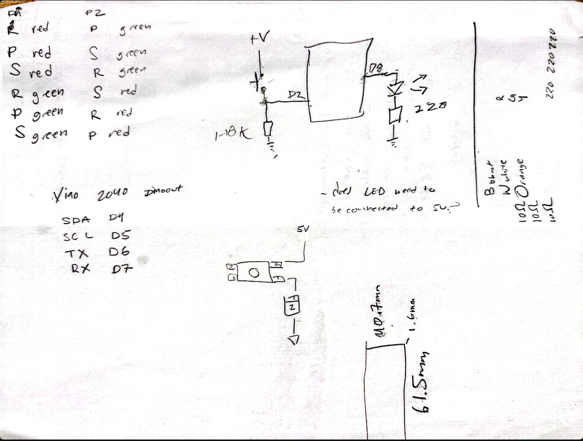
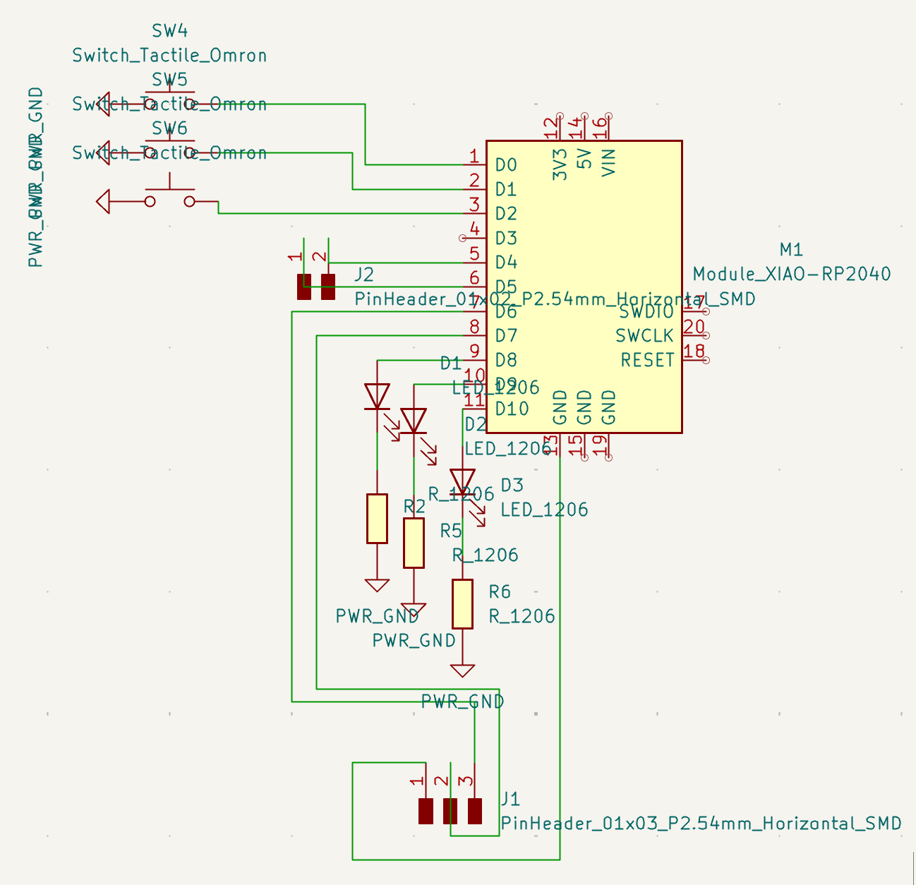
I first started by building my schematic. I placed the RP2040 board and added three LEDs, each connected to 3 220kΩ resistors going to ground. For the buttons, I initially wired them to pins D0 through D2 and added 10kΩ pull-down resistors. The LEDs were connected to pins D8 through D10. I wanted to keep pins D6 and D7 free for RX and TX so I could connect the two boards via serial. I also added a pin header for D54, since that’s the SDA and SCL connection—just in case I wanted to use this board for something else later. Gotta keep my options open!
This was my first iteration, and I actually made three boards with this design. But, it didn’t work. I had to go back into my schematic and rework it. I ended up with a final configuration that uses three buttons with no pull-down resistors, because the Xiao board supposedly has built-in 50kΩ pull-downs, so I’m kinda banking on that working. Fingers crossed.
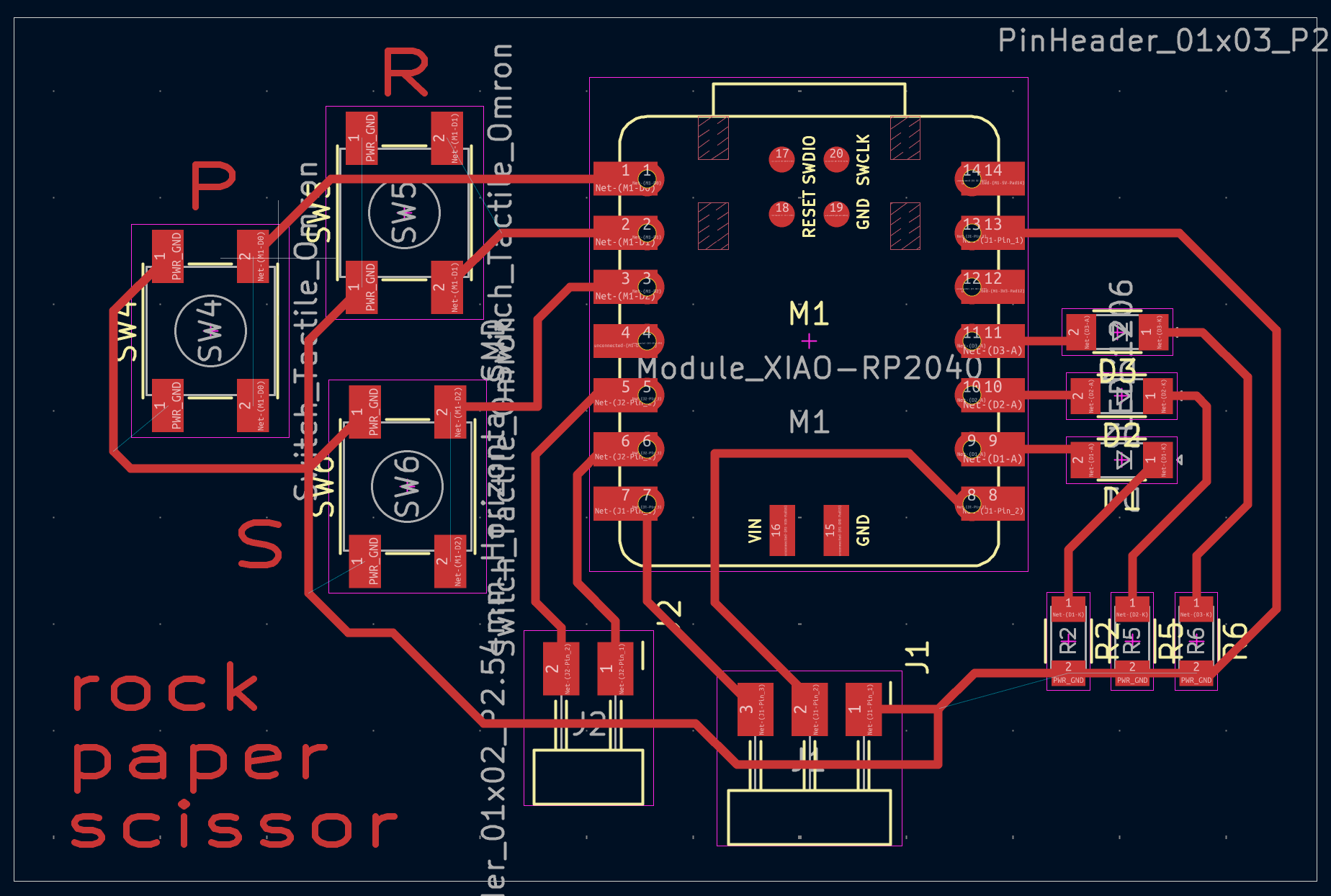
Once the schematic was done, I moved on to wiring it—and oh my god, that part took so, so, SO long. It was such a challenge. In the PCB editor, I knew I wanted the board to be compact and small. I placed the buttons close together for easy access during gameplay, and I made sure the LEDs were clearly visible so you’d know immediately whether you won or lost. I also wanted all the pin headers to be in the same area on the board. That way, I could use the same board for both players and just duplicate it.
I had to make sure the pin headers were set up so I could connect the boards with a long enough cable, giving enough space between the two players. I mean, if the players were standing right next to each other, they’d be able to see each other's choices, and that would totally ruin the game. No cheating!
Download .PNG (edge-cuts)
Download .PNG (traces)
Download .SVG (edge-cuts)
Download .SVG (traces)
Exporting to Adobe Illustrator to Create .PNG
Once I created the design, I plotted my KiCad layout to prepare it for export as an SVG. Then I brought it into Adobe Illustrator. I imported both the edges and the traces, put them on two different layers, and aligned them using the Align tool in Illustrator.
Since I wanted to be material-conscious, I learned how to make the cut happen at the bottom-left corner of the board, using the black square that naturally appears when you import the file. I moved the big white square inside that black square, and then I shifted the entire thing down to the bottom of the Adobe Illustrator canvas—or artboard? I honestly don’t remember the exact word.
Then I exported it as a 2400 DPI PNG and moved on to the next step.


Using Mods
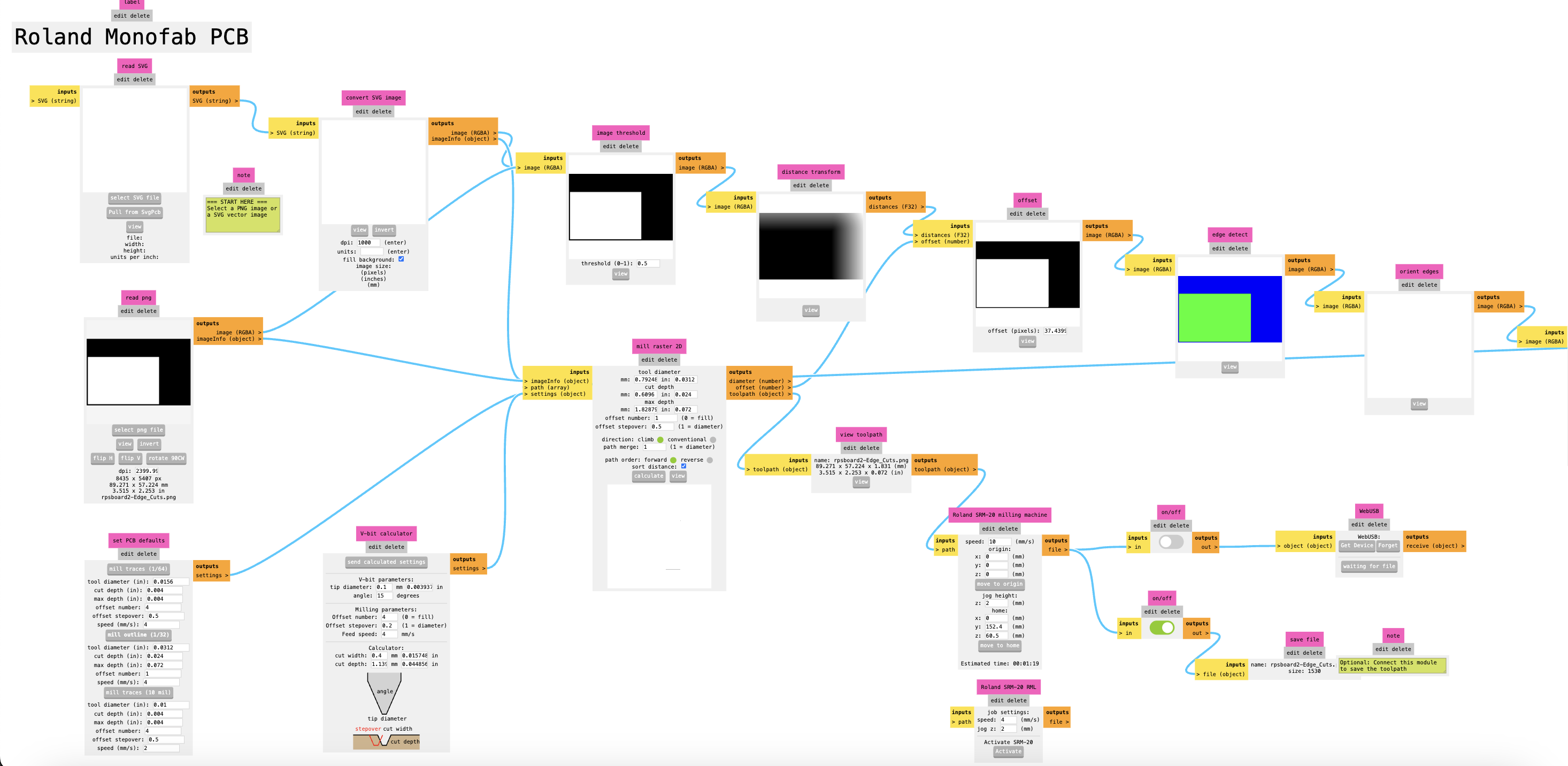
The next step was taking my designs and bringing them into Mods. This part is super important for getting the design ready to be cut by the milling machine. I imported the PNG into Mods and followed the right settings for the Roland milling machine.
Just to skim over it: I imported the PNG, hit "read PNG," selected "mill traces" using the 1/64-inch bit, and made sure it wouldn’t try to save as a web file. I also set the cut speed to 10 millimeters per second. Then I calculated the toolpath and saved it. I repeated the same process for the edge cut.
Now I had two .rml files, which I emailed to myself. After that, I logged into our lab’s milling machine computer and downloaded the files onto it. Then I started the process of setting up the milling machine to cut the boards.
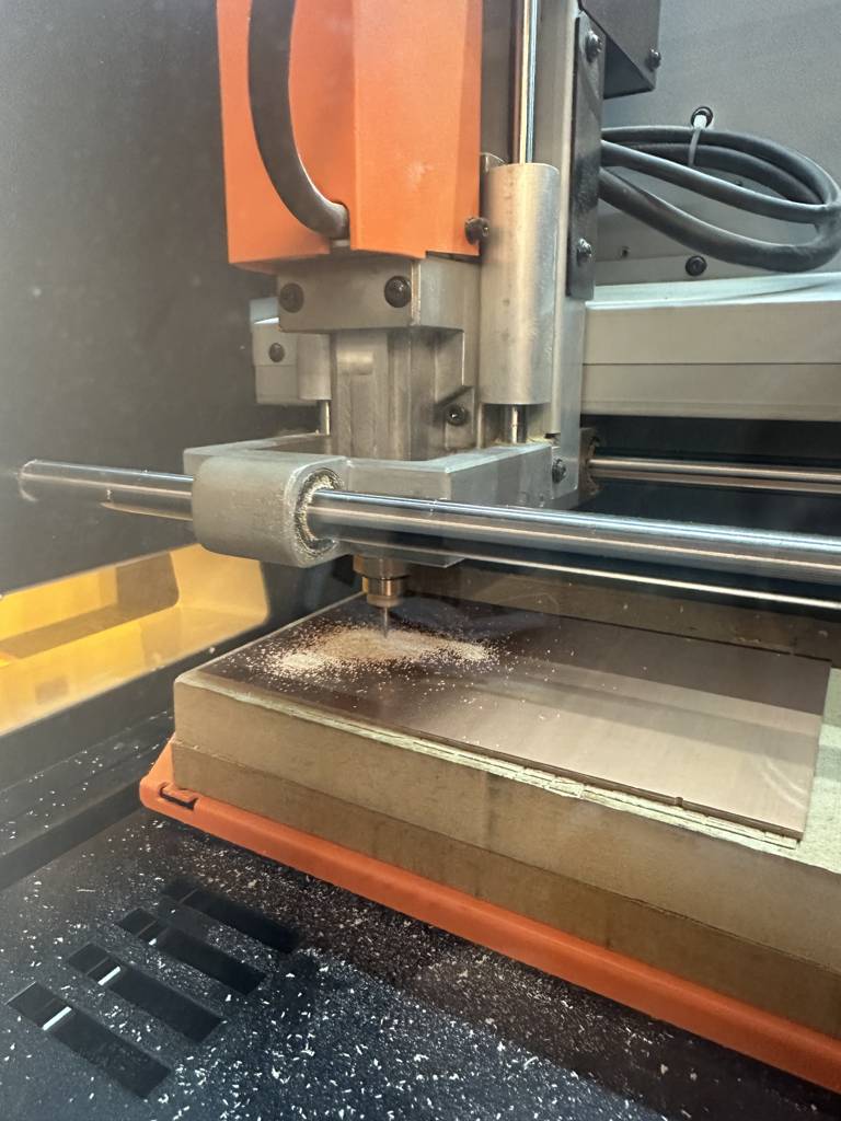
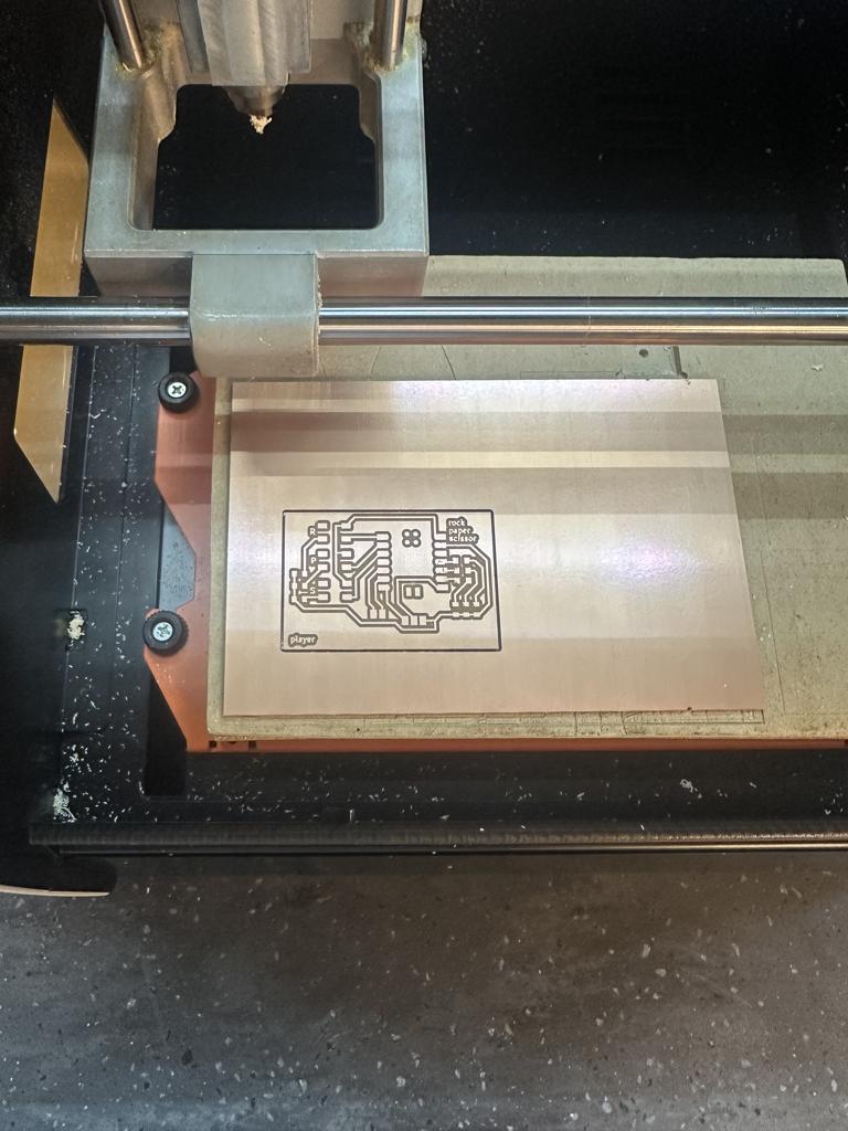
Milling the Boards
Setting up the milling machine has been covered already, but just to recap: I first put four strips of double-sided tape on the copper PCB board and fastened it to the spoil board of the milling machine. Then I inserted a 1/64-inch bit into the mill and calculated the origin. Once that was set, I milled the traces, and then I milled the edge cuts.
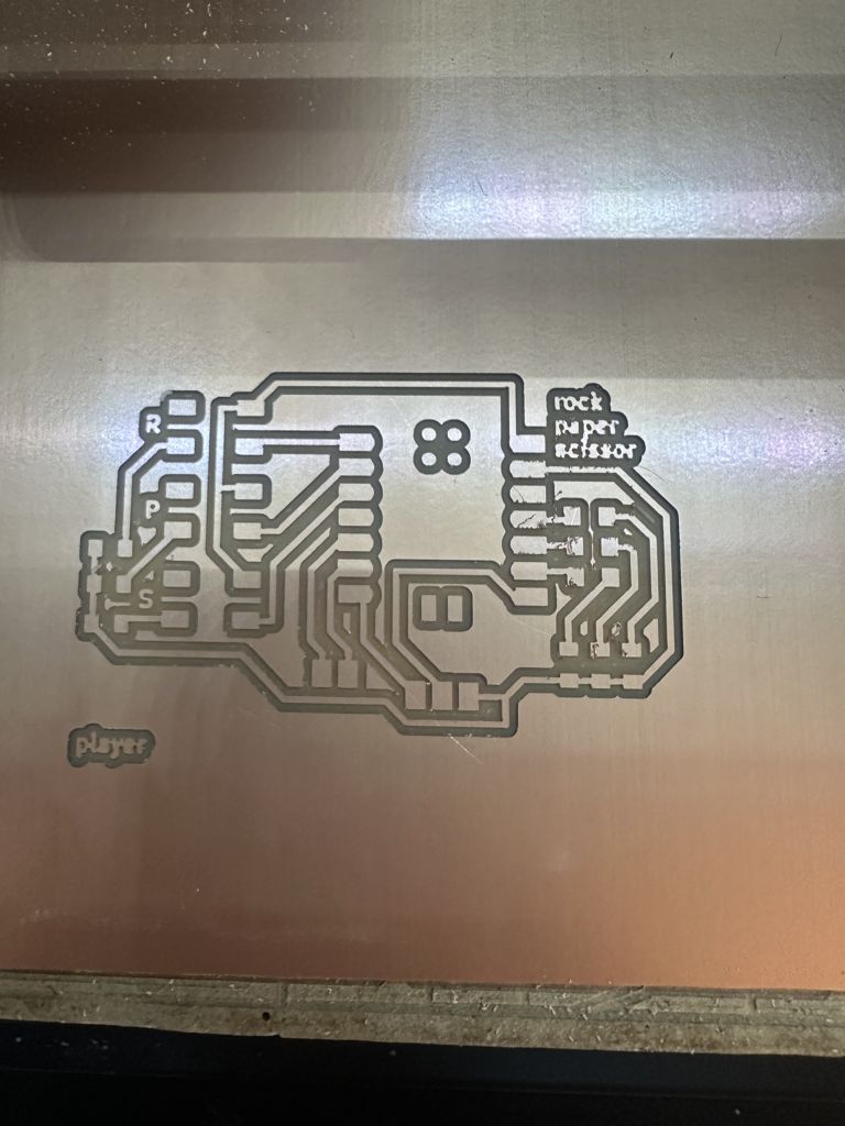
Something I learned during this process was how to save and conserve PCB board. I did this by using the same board multiple times—changing the origin between cuts and even rotating the board 180 degrees to use the other side, instead of starting with a fresh one every time.
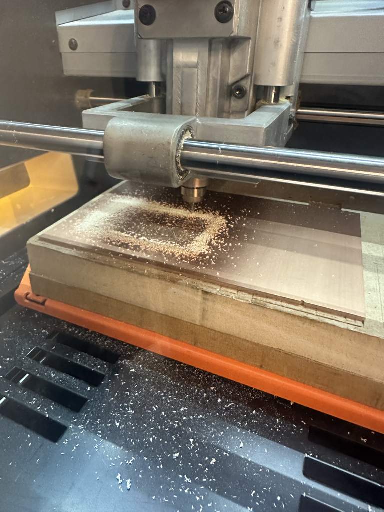
I ran into a huge problem because the perfect bits we usually use were out of stock. I had to use a ball nose-style tip, which I’d never used before, and it caused so many issues. A lot of the time it either cut way too deep or didn’t cut deep enough—it was honestly so frustrating. I ended up milling this board a total of 14 times!
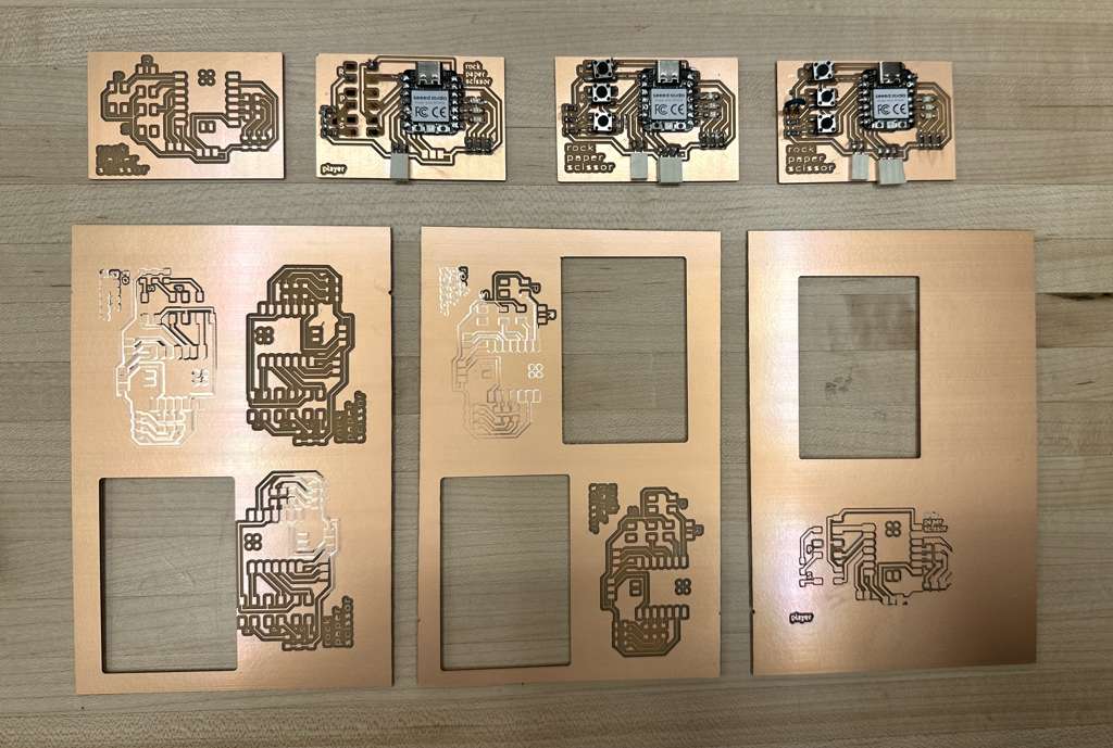
Eventually, I was able to get two working copies of my final board. That was an extra challenge in itself because I wanted to make two of each board, and working in pairs is tough since I can only cut one board at a time. I had to take my time and double-check everything to make sure the quality was solid.
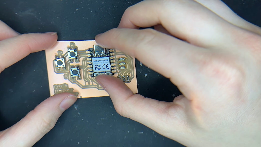
Soldering to the Board
Once I was finally done milling the boards, it was time to take the design I made in KiCad and bring it to real life. For this project, I used one Seeed Studio Xiao RP2040 microcontroller, three LEDs (one red, one green, one yellow), three surface-mount Omron buttons, three 220Ω resistors, a two-pin header, and a three-pin header.
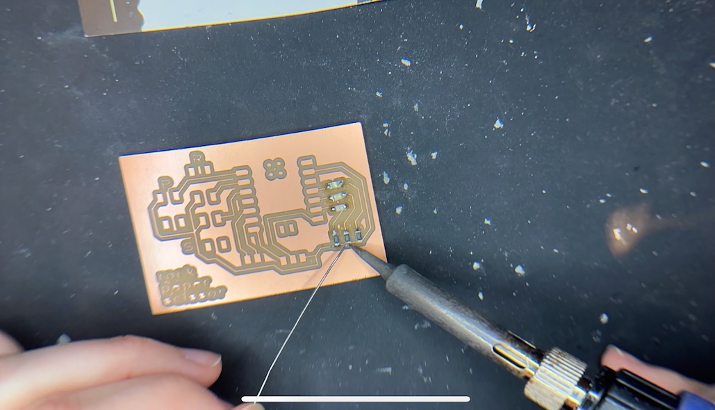
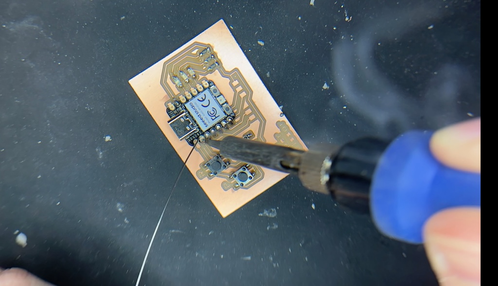
I had to go through many iterations of milling, not because I kept messing up, but because I was making new boards to include all the updated parts I needed. I’ll be honest — I used about five microcontrollers for this project. Each board had its own issues, but in the end, I was happy with the final result.
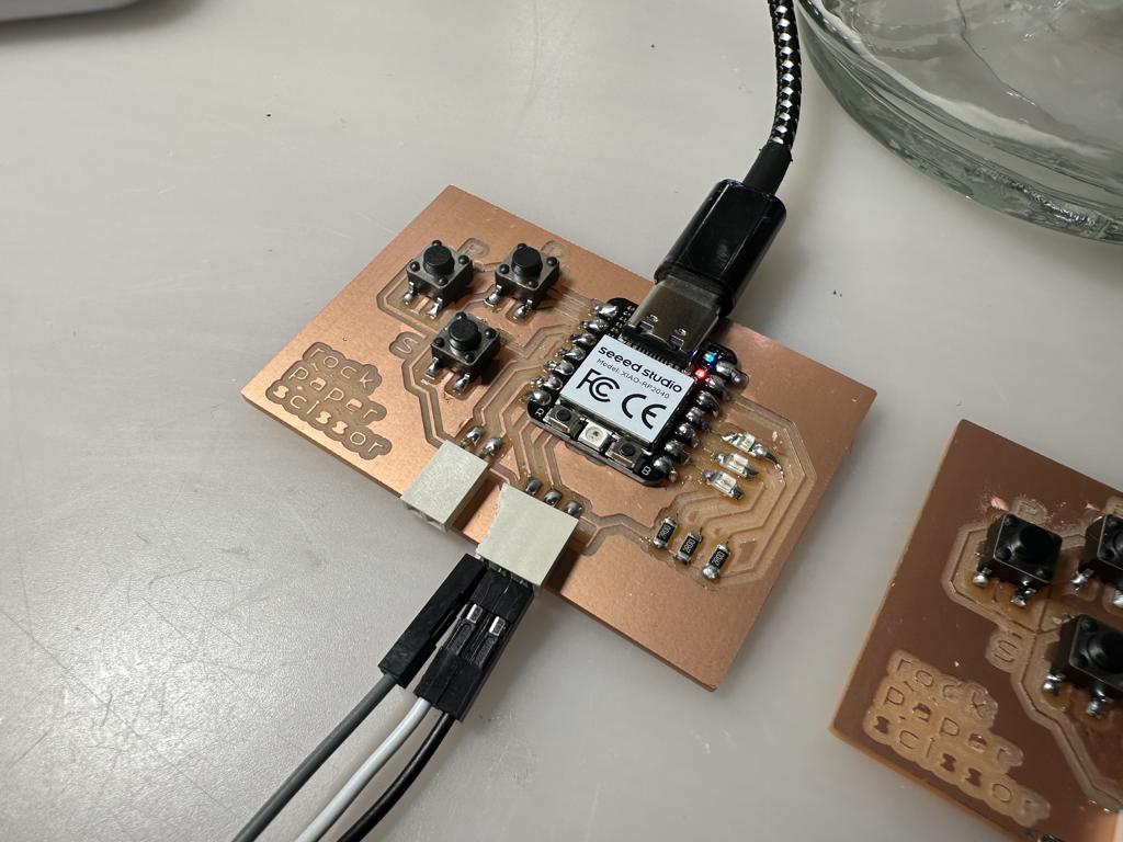
I also chose to connect the Xiao microcontroller to the PCB manually instead of using soldering paste because I felt like I had more control that way.
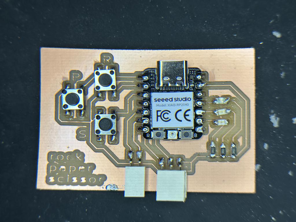
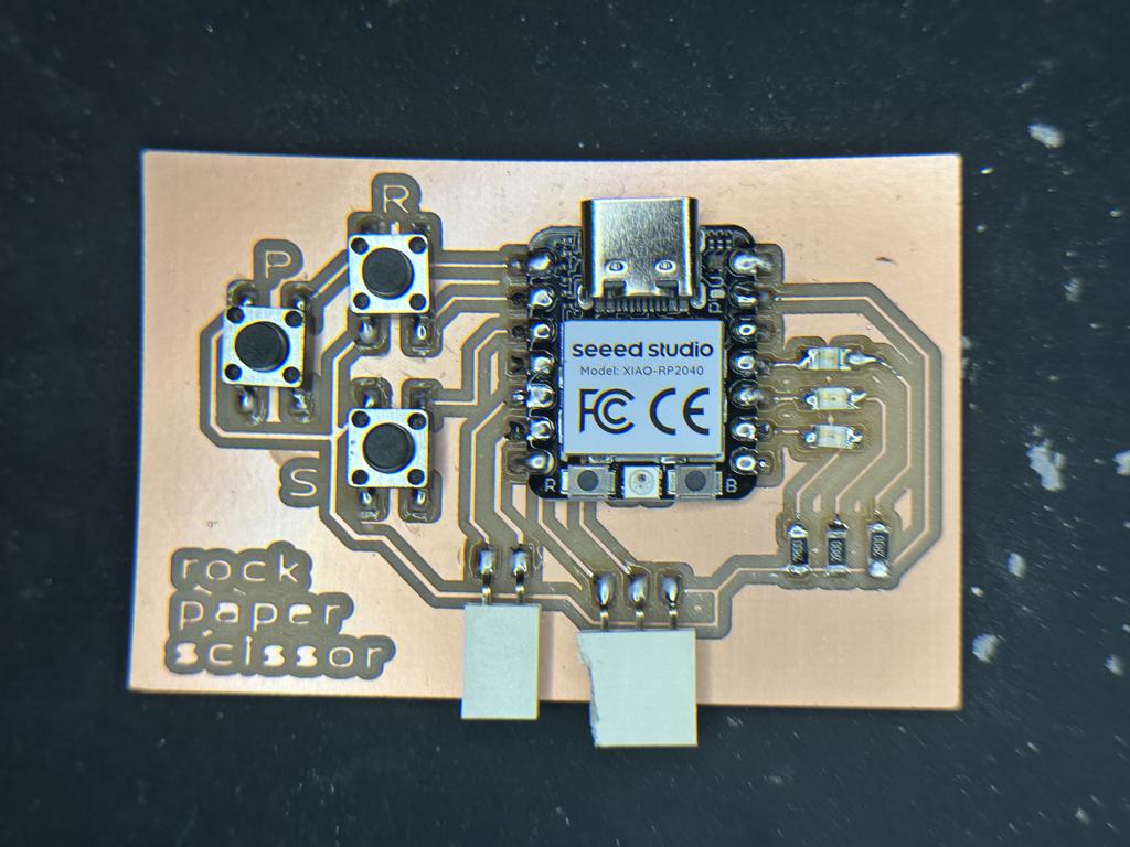
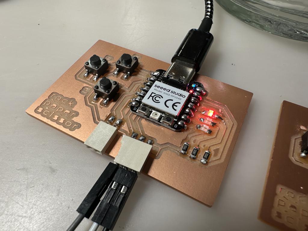
These are my final boards, I needed to make two because each one acts as a controller for 2 players:
Setting up Arduino IDE
Now came the challenging part. The board was fully built, so it was time to bring it into the world of code and actually make it do something. I ran into so many issues—here are just a few.
On the first few boards I made, I accidentally soldered the buttons the wrong way. Every time I pressed a button, it shorted the entire board and disconnected it from the Arduino IDE. That meant I didn’t even have enough time to upload code before the board freaked out. It was such a hard problem to figure out, but thankfully my professor helped me work through it.
Another issue I had was that the code wouldn’t upload at all because my MacBook wasn’t recognizing the Xiao properly. There was a weird issue with a missing .UF2 file. I eventually figured it out by following this tutorial: https://wiki.seeedstudio.com/XIAO-RP2040-with-Arduino/
I made my code and wanted to upload it to the board using the Arduino IDE, so I needed to make sure the correct board type was installed. Following the tutorial above, I had to download an additional boards library specifically for the Xiao RP2040. It’s similar to the Raspberry Pi Pico, but not exactly the same—and it’s not built into Arduino IDE’s board manager by default, which made things tricky.
I followed these steps from the tutorial:
- Go to File > Preferences in Arduino IDE.
- In the Additional Boards Manager URLs field, paste this URL:
https://github.com/earlephilhower/arduino-pico/releases/download/global/package_rp2040_index.json - Then go to Tools > Board > Boards Manager…
- Search for RP2040 and install the latest version of "Raspberry Pi Pico/RP2040."
After all that was set up, I still had issues understanding what port my computer was using. There was this random /dev/cu.debugconsole port showing up, but I needed something like /dev/cu.usbmodem to actually upload code.
I finally got the right port to show up when I put the Xiao into bootloader mode. To do that, I pressed the "B" button on the board while plugging it into my computer. After that, I went back to Arduino IDE, uploaded some sample code... and it worked!
Creating the Code
In my first set of boards, I had a frustrating issue where every time I pressed a button, the entire board would disconnect. These boards were able to run simple blinking code, but instead of lighting up the actual LEDs I had soldered on, only the onboard LED on the Xiao RP2040 would light up. Eventually, I realized the problem was that I hadn’t clearly specified which pins everything was connected to.
Once I mapped everything correctly, it finally started working. Here's how I assigned all my pins:
- Buttons:
- Rock – D1
- Paper – D0
- Scissors – D2
- LEDs:
- Red – D10
- Yellow – D9
- Green – D8
- Serial Communication:
- TX – D6
- RX – D7
I used ChatGPT to help me create and troubleshoot the code throughout this project, and it honestly made a huge difference. It helped me iterate through different versions and figure out what wasn’t working. One of the biggest breakthroughs came when I ended up remapping my buttons with ChatGPT’s help. That turned out to be the final puzzle piece I needed to get the game working smoothly.
Button Orientation Diagram:
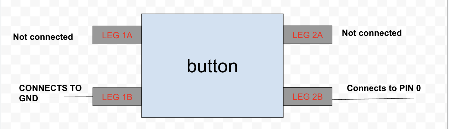
Based on the pin assignments I listed above, I had ChatGPT check my code and help me align everything with my original game logic.
As my design for the game developed, I decided I wanted to make it more festive and interactive. Before the game begins, I wanted the three LEDs to flash and rotate through each color for about five seconds. Then, the players would start pressing their buttons. After five button presses from each player—technically five rounds—the game would end.
At the end of the game, the boards would communicate to figure out the winner. Then, there would be another round of blinking lights, followed by the winner’s board lighting up green and the loser’s board lighting up red for about five seconds. I added this final touch pretty last minute because I wanted the game to feel more playful and engaging.
I also didn’t include a time constraint between rounds, because in real life people usually say “rock, paper, scissors, go!” and then hit the button. I wanted to build this project around actual human behavior and interaction.
ChatGPT Prompting
I am not very good at coding. Not good at all. So I created the code for this project with the help of ChatGPT. This was the first prompt I used.
From here, the code was not working because the pins were not programmed the right way. Also, this was code that I had generated before I discovered that my board was not properly laid out so I needed to reupdate the chat. This is the new prompt I wrote.
Now this was good, but the game seemed not so fun and I wanted to make it more engaging. So I wanted the code to be updated so the LEDs flashed more colors.
Just as Fab Academy loves to promote iteration, I embodied that quality through my chats with the bot. I was inspired and new ideas kept popping up into my head as I watched the board change and update. This was the new prompt.
The code used in the game: written by ChatGPT under my prompting
Testing
Moment of truth. Was the last week going to prove to be a good and productive use of time? Or would my project fail again? It was hard to think so deeply between my bated breaths as I plugged in my Xiao RP2040 microcontroller.
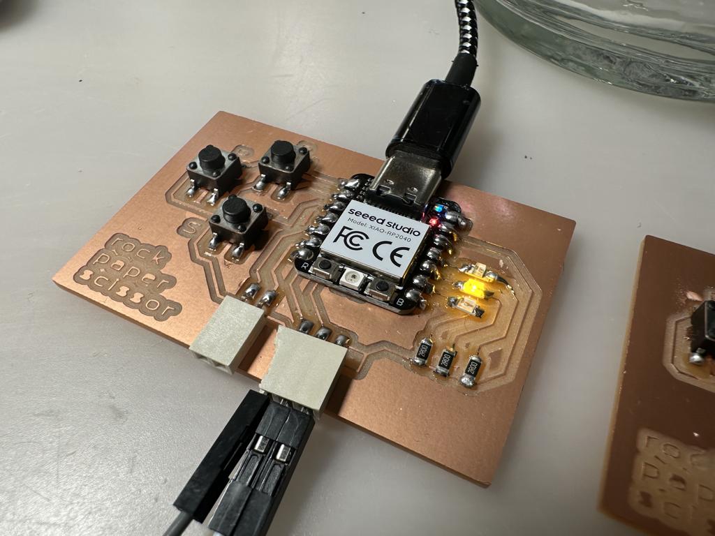
The light blinked. Then again, and then nothing. And then two yellow and then...
BAM! Party mode!!!!! My game worked!
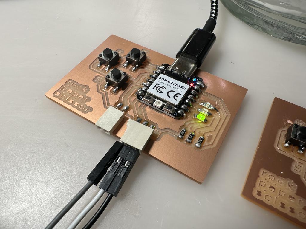
rock, paper, scissors game