5. 3D Scanning and Printing
This week I learned about 3D scanning and expanded my knowledge about 3D printing.
Research
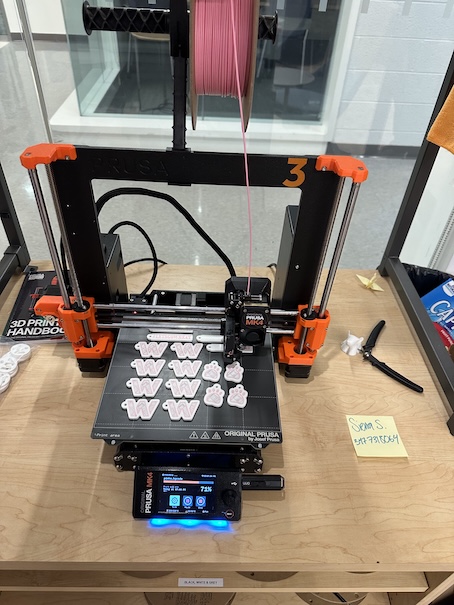
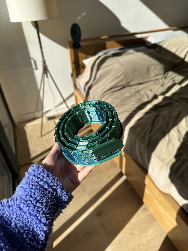
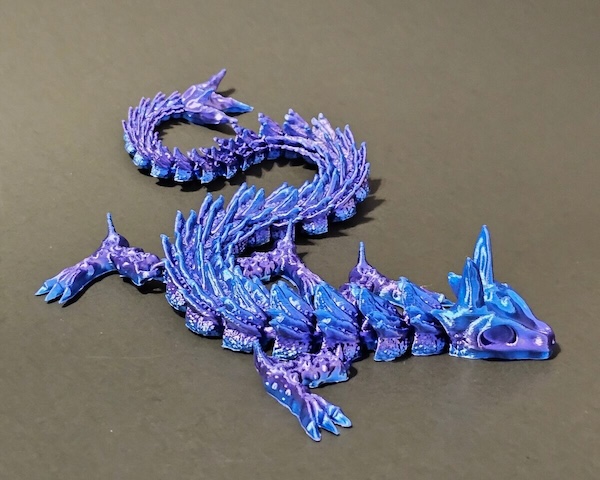
I have had some experience with 3D printing and have been using 3D prints comfortably for many years. I’ve always been fascinated by the ability to design something on a computer and have it magically come to life. This week, I wanted to explore different 3D printing techniques and focus on creating my own designs rather than just printing models I find on Printables or other online sources. Previously, much of my 3D printing experience involved discovering cool prints, such as ball-jointed dragons, miniature cities, and designing custom name tags for my birthday. For this project, I wanted to create something that would actually help me in my everyday life—something functional that could make my daily routine easier.

• • • Making 3D Design
Inspiration
For this project I wanted to create something that I would be able to use. My friend's AirTag keychain fell off her AirPods, so I wanted to create a case that would hold the airtag in it. I studied other 3D print designs to get a sense of how I would go about making the design. I printed out these two designs from Printables.
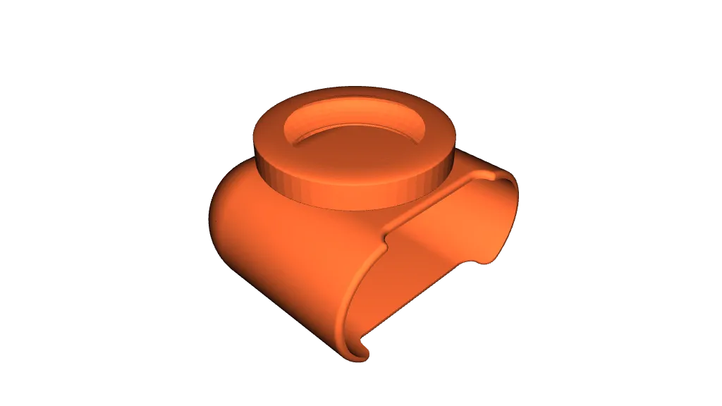
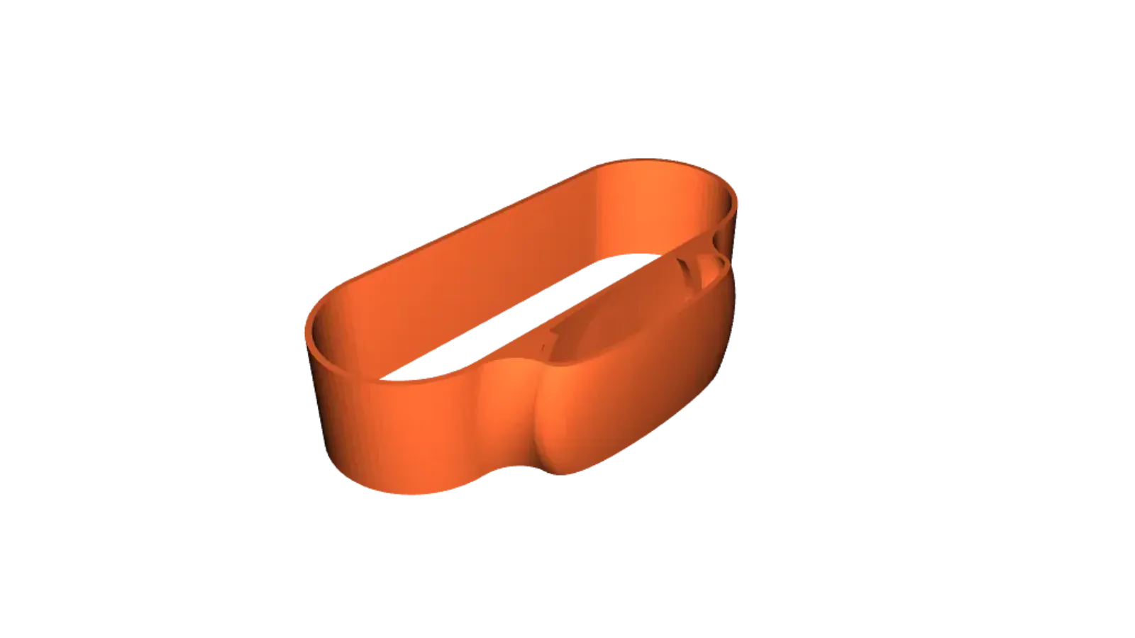
Find those designs here and here.
However, a major constraint upon printing and testing these models was that my friend's airpod case was not the official Apple one and so the size of her case is the same size the online models were designed for, so they didn't fit. I had to create my own 3D design, taking my own measurements.
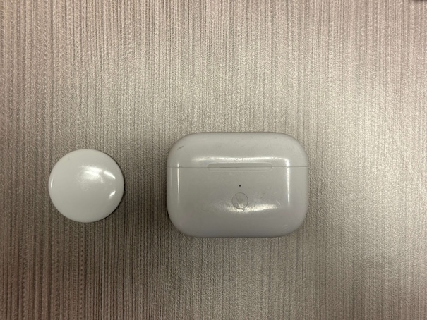
Design Measurements
I used Fusion to model the airpods case for this project. First, I devised a plan on how I would keep the measurements of the airpod case organized, because I knew I wanted to use the parametric modelling feature of Fusion to manage my design. I came up with the following drawing and parameters;
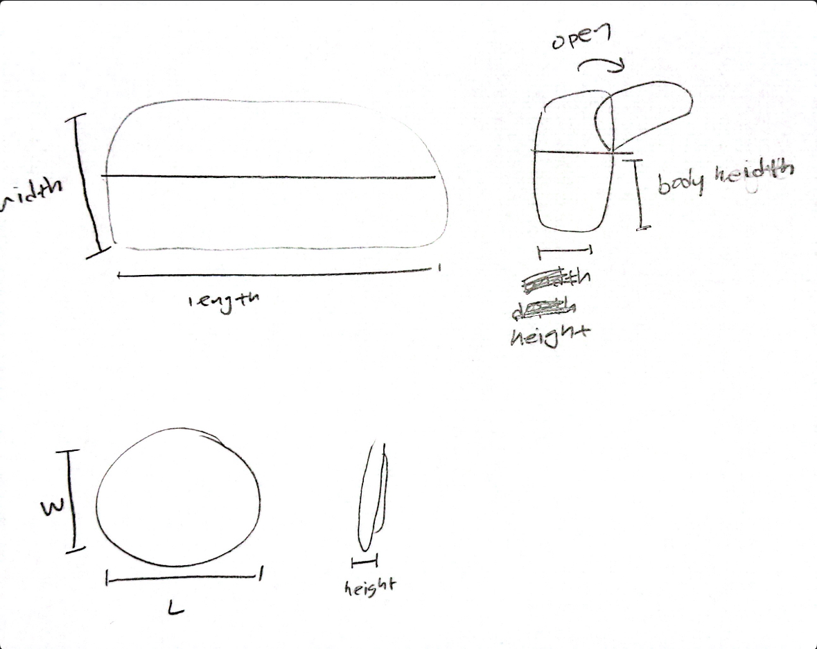
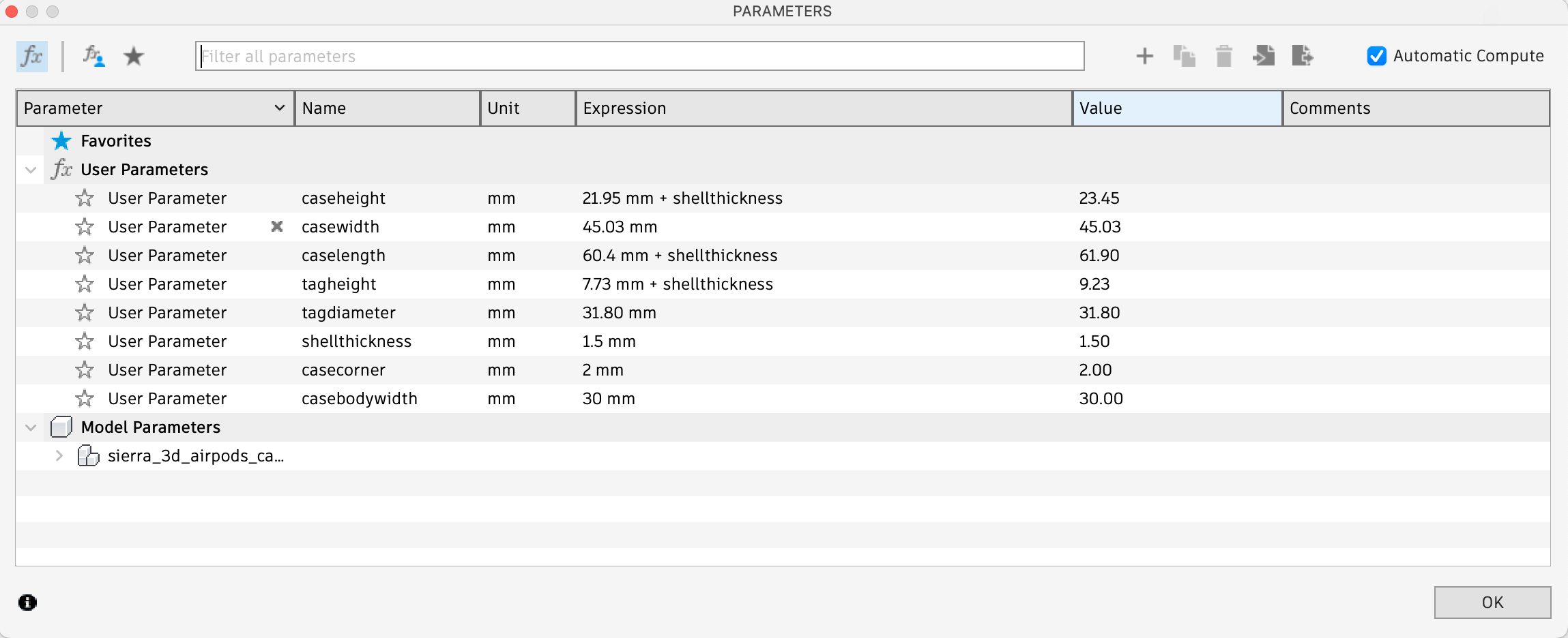
I used digital calipers to measure the airpods. The dimensions of the case itself was 21.95mm x 60.4mm x 30mm (caseheight, caselength, casebodywidth). I calculated the casebodywidth by measuring from the bottom edge of the case to the part of the case where the lid lifts. This is because I didn't want the case edge to prevent the lid of the case to open, as it opens backward in a flip-back style.
As the airtag is an ellipsoid, I needed to measure the apex of the shape so that no matter what there would be enough clearance for the airtag to fit neatly into my design. Part of the requirements for this week was to create a 3D printed object that could not be producted subtractively, meaning there needed to be enclosed/enveloped parts. My measurement for the airtag was found to be 7.73mm x 31.80mm (tagheight, tagdiameter).
Modelling in Autodesk Fusion
With these parameters, I was able to start the design. I created a sketch and drew a rectangle. I used the Sketch Dimension feature to be able to use parameters to define the size of the sketch. I set the width to casewidth+shellthickness and the length to caselength+shellthickness. I needed to include the shell thickness parameter as part of this because the size of the new 3D print case would have a thickness. I determined this to be 1.5mm based on the other similar designs I printed to experiment with. I finished the skethc, and I then used the Shell function by selecting the top of the case and creating a shell and a hole. When I did this, I made sure to create the shell going outward from the design and adding 1.5mm, so that it would not take away from the actual size of the airpods case that would need to fit isnide.
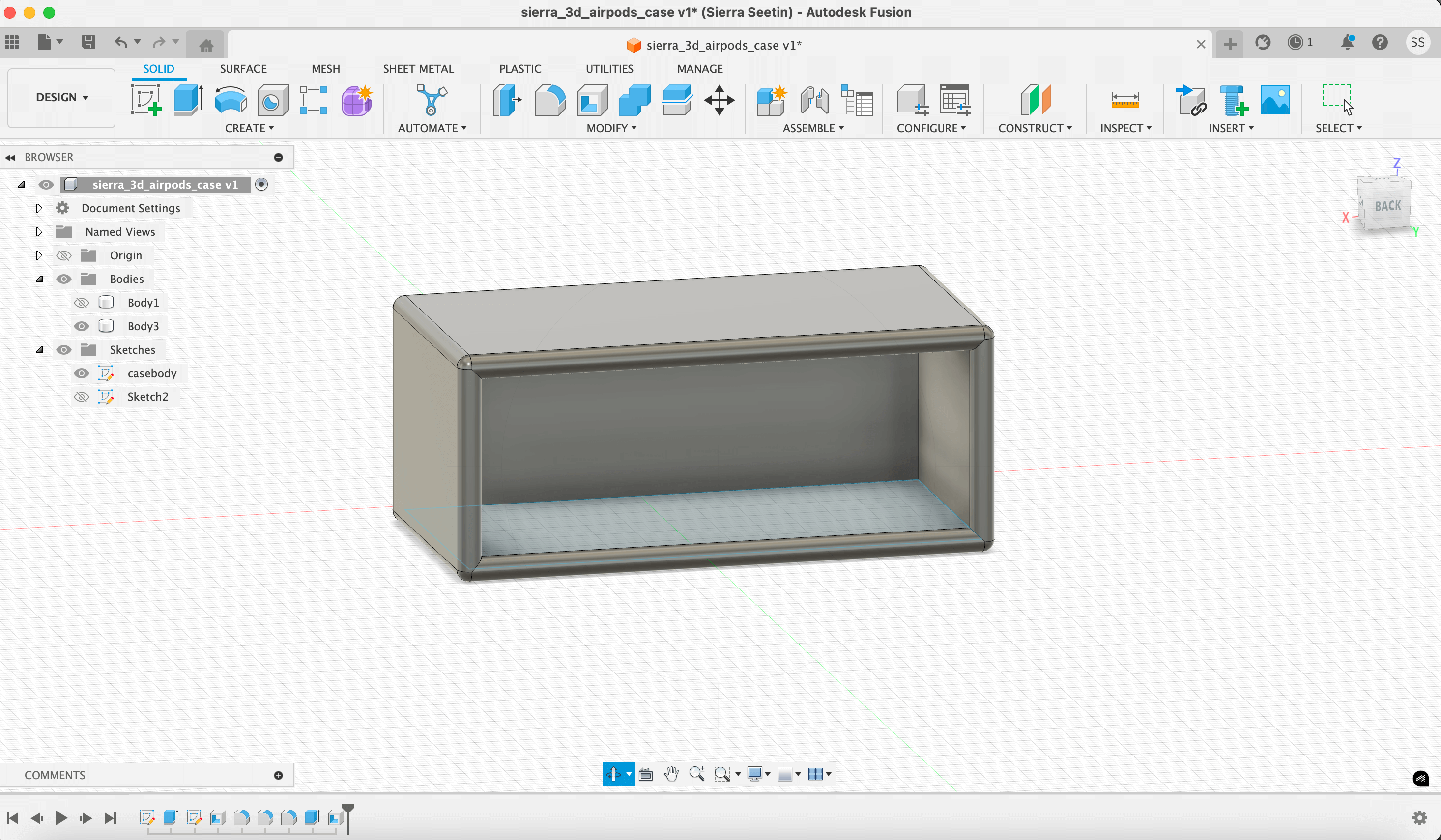
Then, I made the the space for the airtag to sit in. I selected the surface on the x plane and created a new sketch of a circle. This circle was defined as tagdiameter+shellthickness.
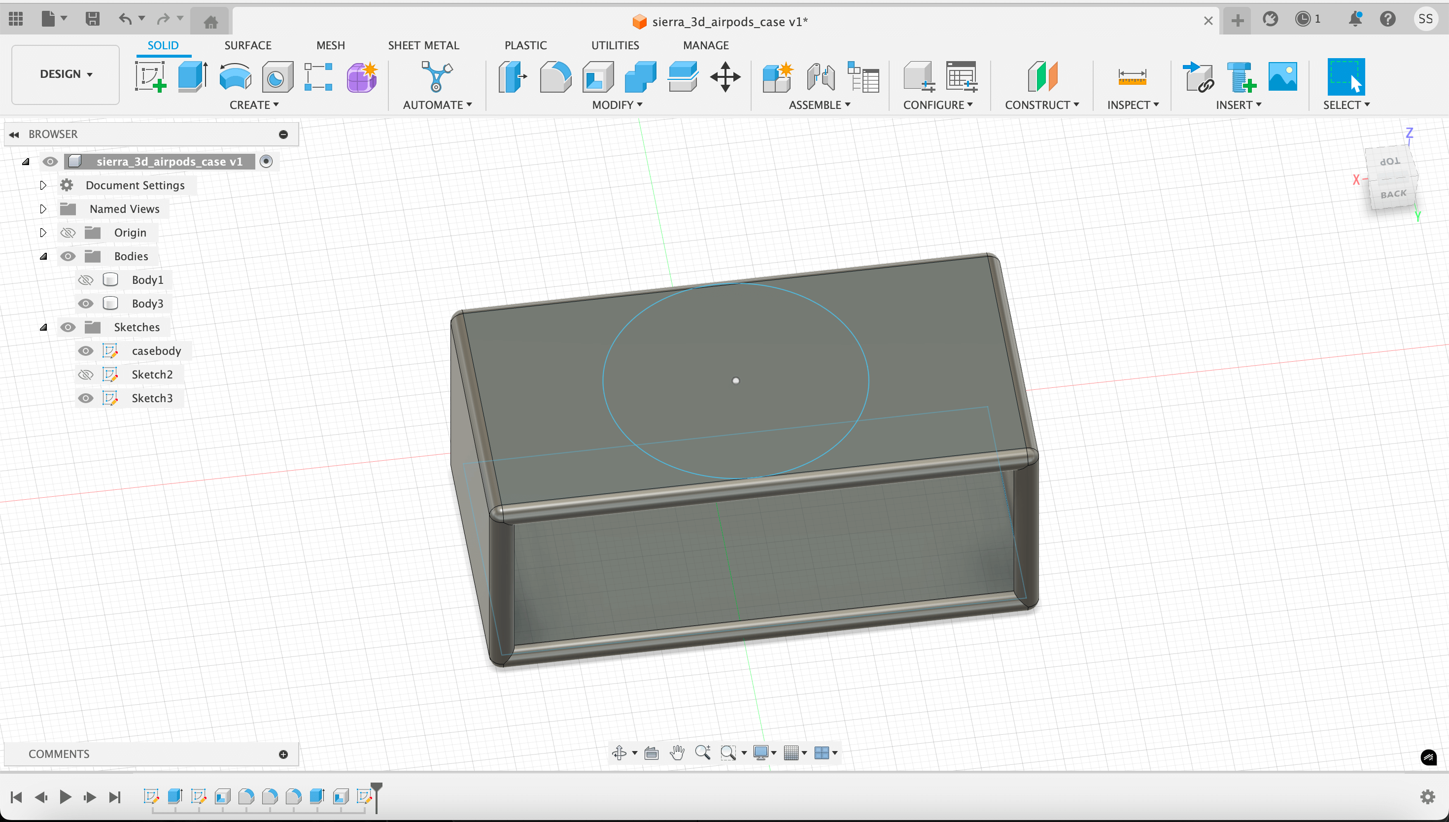
I finished this sketch, and extruded it. I made this extrusion height tagheight+shellthickness. There seemed to be some clipping with the circle and the flat surface of the case, which I think was the result of the curved edges that appeared when I performed the Shell function previously. I didn't want to make the width of the case larger because I ran the risk of the case lid not fully openning. I couldn't undersand how to prevent this from happening.
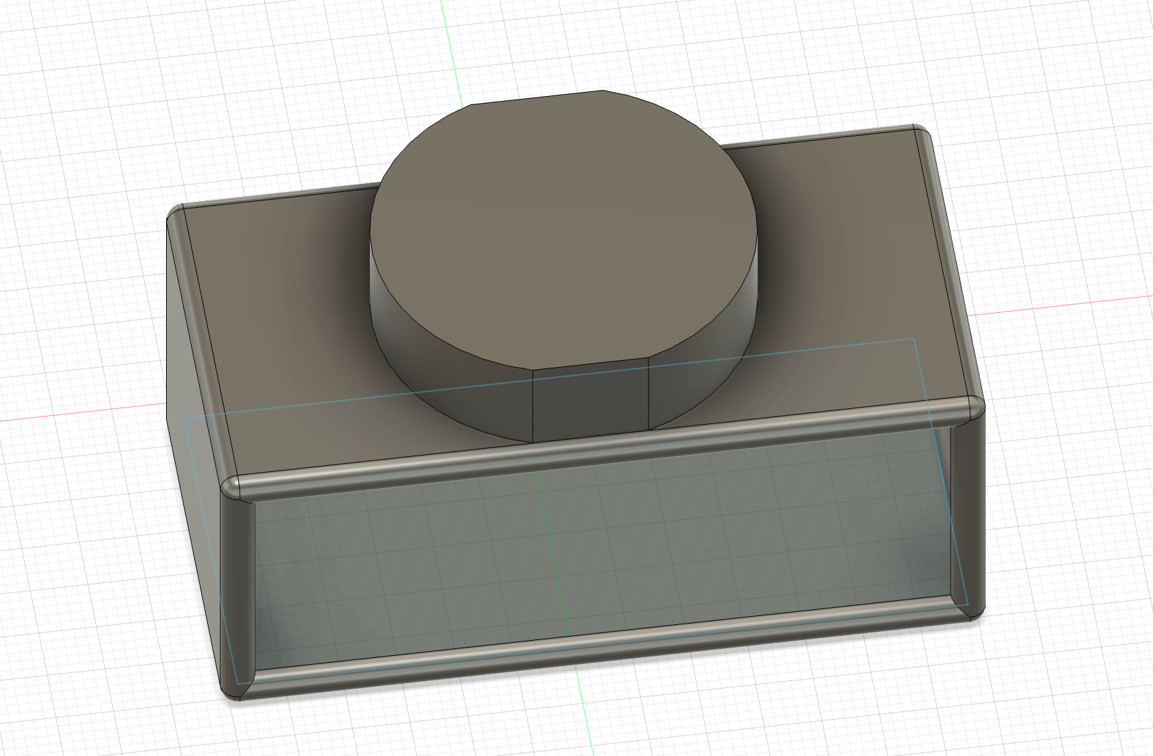
Next, I needed to create the hole for the airtag to sit in. I used the Hole function on Fusion to create this. I had a lot of trouble trying to get this to work. I turned my design around so that I could look into the inside, and clicked on the plane directly beneath the airtag slot. I created a hole with the diameter tagdiameter and a height of tagheight-shellthickness. I needed to subtract the shellthickness from the height of the hole because I included shellthickness in my parametric declaration for tagheight because I needed to go back and change the size of things but I couldn't get back into sketch mode. Below is the hole drill setting I used as well.
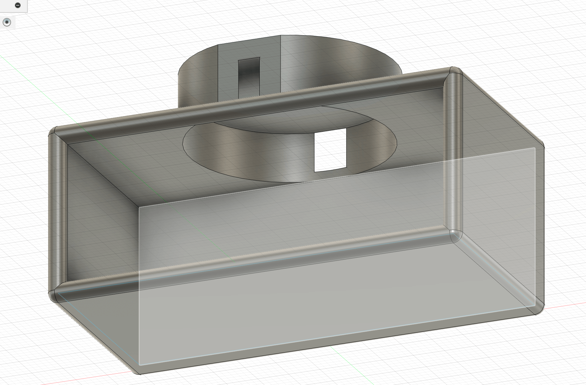

This was my final parametric 3D design. I exported this as a .stl file so that it could be brought into Prusa.
Download .DXF
Download .STEP
• • • Process of 3D Printing
Setting up Prusa Slicer
PrusaSlicer is a slicing software used to convert 3D models (STL, OBJ, or 3MF files) into G-code, which is the set of instructions a 3D printer follows to print an object. It allows users to adjust settings like layer height, print speed, infill density, and support structures to optimize print quality.
First, download Prusa Slicer. Install it on your computer and launch the software.
Open PrusaSlicer and go to the Configuration Wizard (found in the top menu under “Configuration”). Navigate to Prusa Research and select the printers you're using. My lab has the Prusa MK4 printer, but we can choose to print using either Input Shaper mode or MMU3 mode.
The difference between the two is that Input Shaper mode is optimized for reducing vibrations and improving print quality at higher speeds, making it ideal for single-material prints with smoother surfaces and less ringing. On the other hand, MMU3 mode is designed for multi-material printing, allowing the printer to switch between different filaments during a single print, enabling more complex and colorful designs.
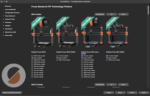
Ok, now time to configure filament settings. I am using ordinary PLA filament for this project because I just want to make a simple thing that doesn't need to be extremely durable, have unique properties and I want to be able to iterate without wasting lots of expensive filament.
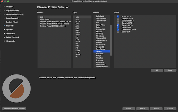
I chose these settings because my lab uses generic third party PLA filament for most projects, which works perfectly and is less expensive. It does the same job (do you buy expensive offical ink cartridges or whatever you can find on amazon...?) It is important to set this up in Prusa Slicer because the program will take into consideration the material you are printing your design with in order to generate proper G-code (program) that will tell the printer how to print with the specific type of filament you want. Different filaments print at different temperatures, speeds or can just be more finicky.
Press finish. Now, you are ready to bring in your design!
Import .STL File
Once I had my design, in .stl format, I needed to get it into Prusa Slicer to prepare it for printing.
Press the Add icon in the top left corner of the toolbar.

Select the .stl file you wish to print.
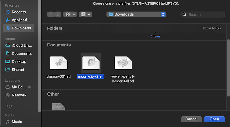
Now, your design is open in Prusa slicer.
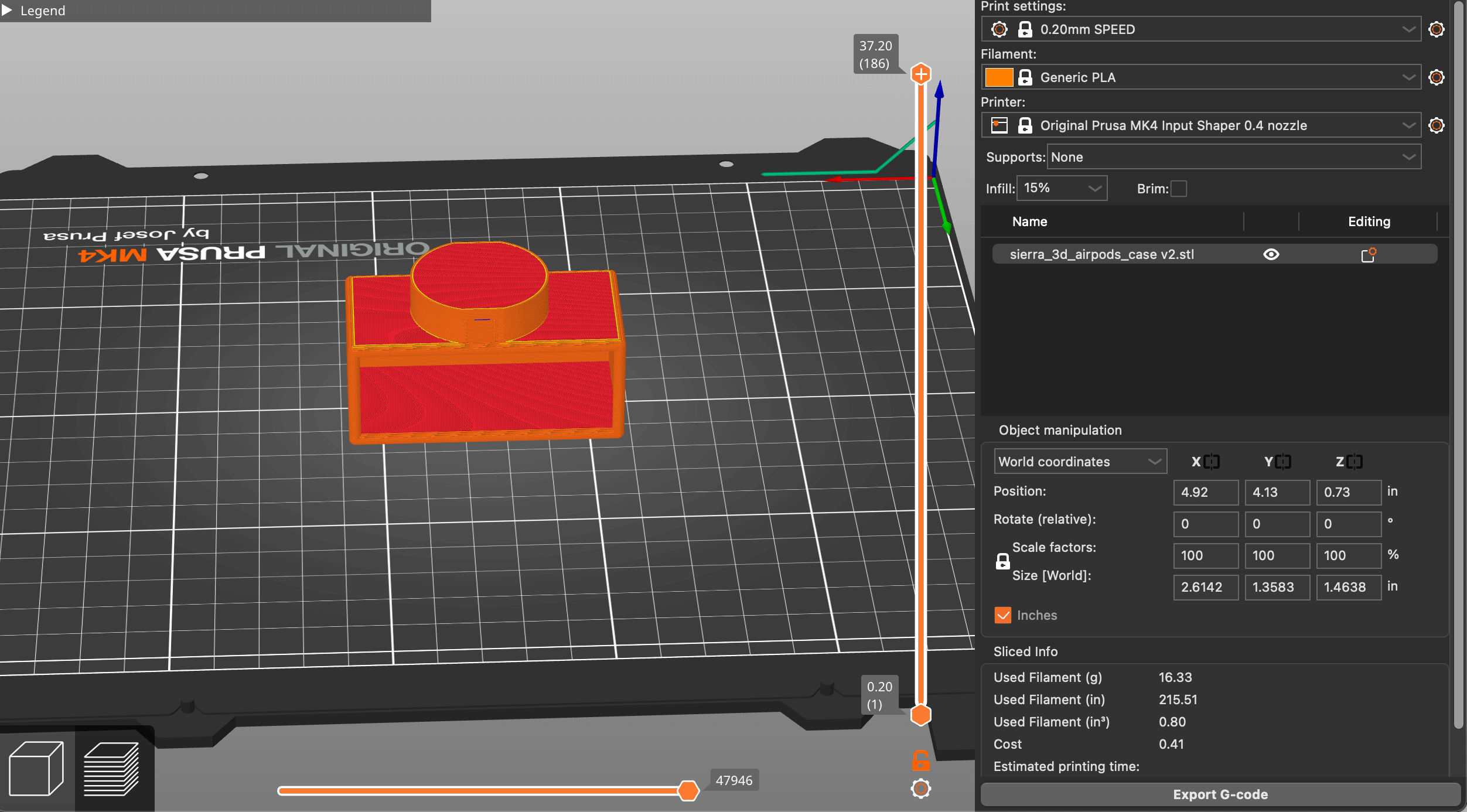
Configure Print Settings
Now we are going to configure the print settings so that the design comes out as we envision it should. Not that this always works. But if you follow my documentation (hopefully) you will have a higher success rate. You WILL succeed.
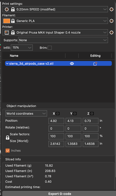
- Print Settings: I was not in a time crunch so I used the most standard .20mm SPEED nozzle. If I needed the print to print faster, while sacrificing print quality and run a higher risk of print failure, then I would have used the .10mm nozzle. If I needed more details on my print I would chose a nozzle that prints at a slower speed to protect quality.
- Filament: I used generic PLA filament for this project.
- Printer: As set up in the settings, I use a Prusa MK4 Input Shaper .04 nozzle.
- Supports: I chose to print this without supports because the supports proposed by Prusa were too invasive and wouldn't allow me to add a foreign part in during the printing process because it would take up space.
- Infill: This I kept at 15% because most of the print wall had no infill volume because they were so thin. The areas that did I figured would need more infill to make up for the lost integrity in the thinner parts of the print. To increase speed and reduce material use I could alter the infill pattern and density.
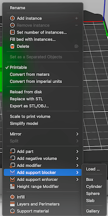
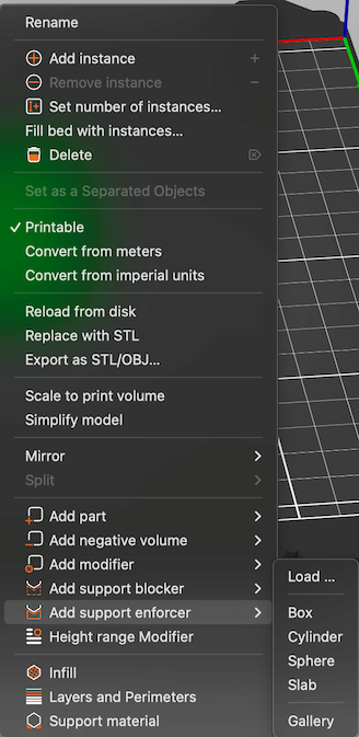
While in this print I didn't use supports, I did experiment with settings. I tried the support everywhere option yet it generated the supports in places that would be too hard to remove without damaging the rest of the print. I played around with support blockers, which would prevent supports in a certain area from printing. I tried support enforcers to add supports in a specfiic area yet I was having problems with this. My biggest worry was printing the supports in a delicate area and sabotaging the entire print in trying to remove them.
Export G-Code
Once I set the specfications in Prusa, I exported the g-Code to a flashdrive which I would then plug into the 3D printer.
Preparing 3D Printer
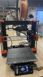
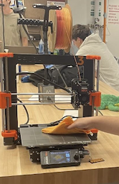
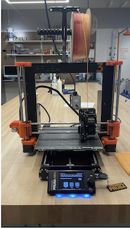
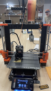
- 1. Loading Filament After picking the color I wanted to use, I fed the filament into the nozzle and it began to heat up. When loading the plastic, I cut the tip at a 45° so that it would fit easily into the machine.
- 2. Prepping Print Bed I sanitized the print bed and rubbed it with a microfiber cloth.
- 3. Starting Print I plugged the USB into the machine and transferred the G-code to the printer and began the print.
- 4. During Print The printer began to form the first layer of the print.
- 5. Completed Print After an hour the print was complete.
- 6. Removing Print Finally, it's done! It can be popped off the print bed.
Final
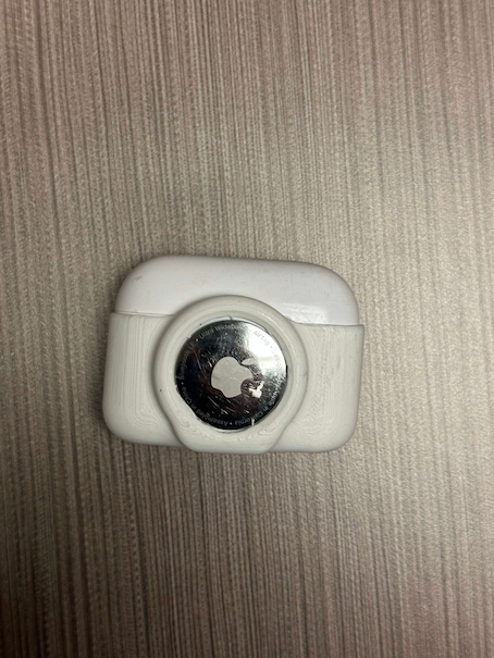
This is my final print. It took about an hour, and it did fit the airpods case and the airtag. However, because I chose to print without supports the inside of the case is rough and not smooth, and there are weak spots. I am not full happy with this print. I know I need to go back and edit my 3D design in Fusion for it to be able to make a better .stl file to print. Overall, the case is successful but not ergonomic as I couldn't understand how to do curves and measure the curve in Fusion. A lot of my disatifcation is coming from my design so I just need to go back and tweak it.
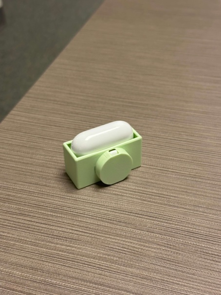
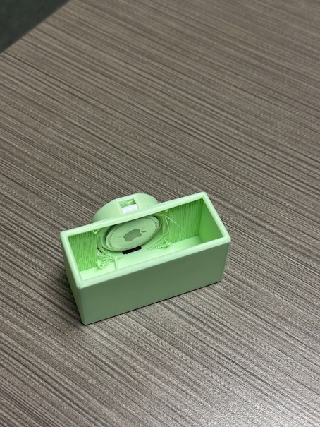
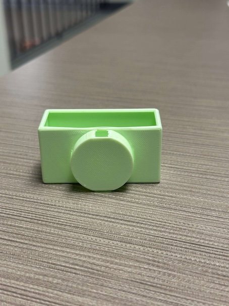
• • • 3D Scan
I used PolyCam to scan my surroundings (and myself) to create a mesh of me. A scan of me. Holy future!
Download PolyCam
On my iPhone, I downloaded PolyCam and created an account. I needed to give camera and microphone permissions. Onto creating my first scan!
Making Scans
I first started off small and just did a scan in a 5' x 5' area, of a person from the waist up. It was not very good. Then I stood up and got a full bust scan which I cropped. I even played around with the Room function on the app. These were just experiments.
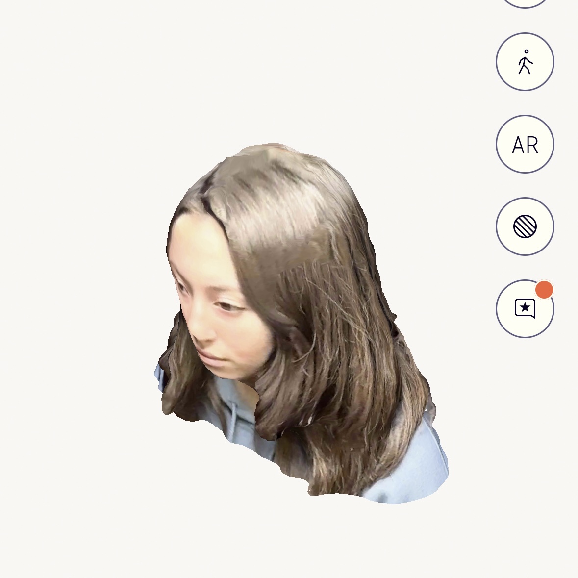
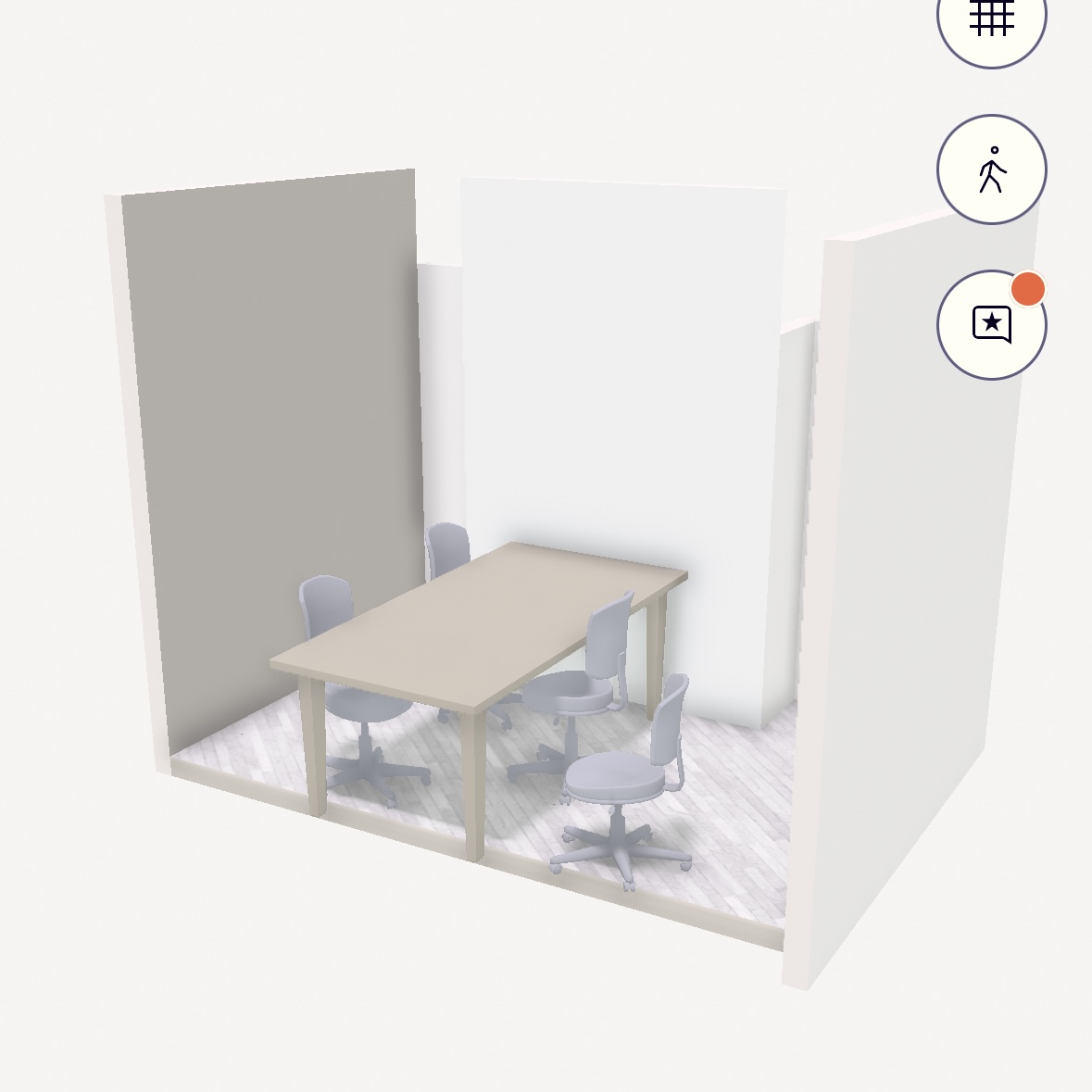
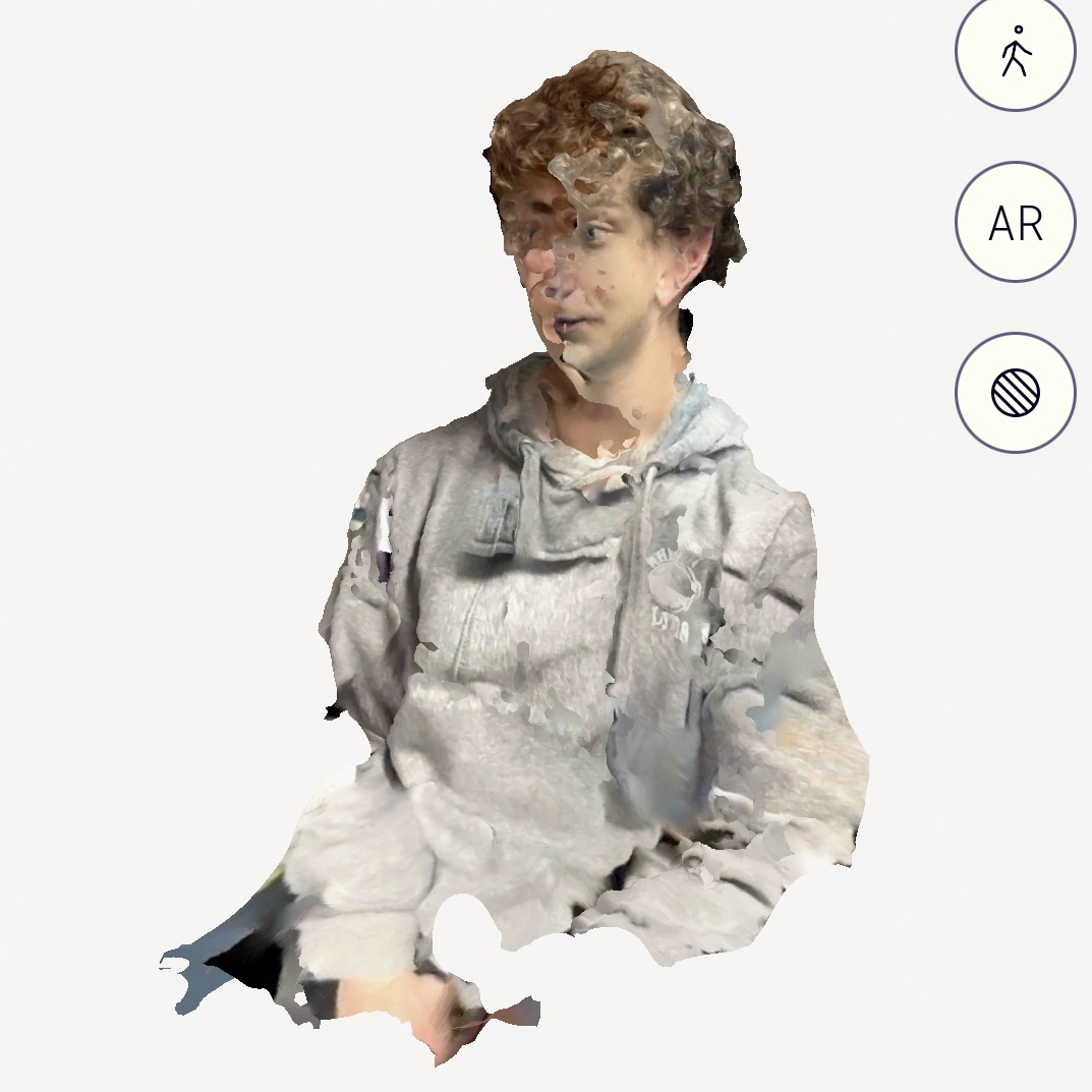
Then I got more serious. I tried a scan from farther away.
This was the processing part of PolyCam. I thought it looked cool still. The green diamonds represent the intervals at which the PolyCam app took pictures to create the scan.
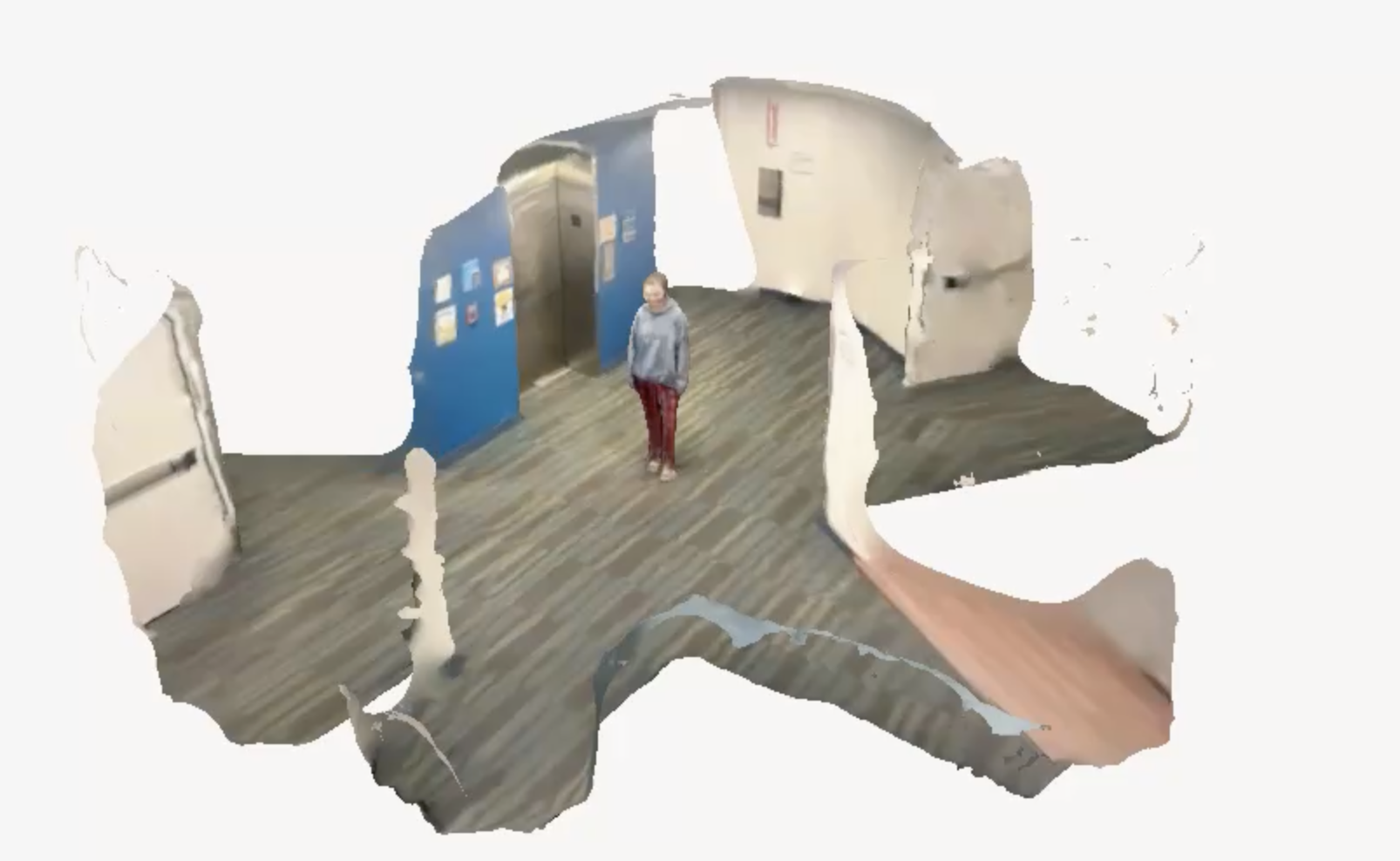
A .GIF
I was very happy with how this turned out. I downloaded the video.
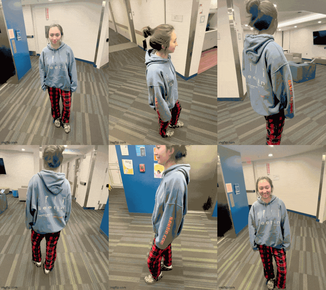
I also made a .GIF of all the pictures the PolyCam took to make the scan, and it looks great! I can see why there was inconsistencies in my face scan becaues I smiled and then stopped smiling and then moved a little bit. I will make sure to not move in future scans, haha.
Final
I also made an embedded version of the PolyCam scan, maybe it's working now.