2. Computer Aided design
This week I developed my 2D and 3D modelling skills and experimented with different software.
Research
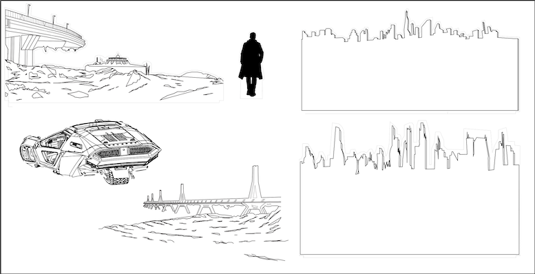
For this week’s Fab Academy assignment on computer-aided design (CAD), I used Fusion 360 to model a simple, movable invisibility cloak concept. Inspired by optical cloaking research, I designed a multi-lens system based on the Rochester Cloak, which bends light to hide objects.
Since I wanted a functional and adjustable design rather than a fixed structure, I avoided complex nanotechnology or precise mirror placements. I created basic sketches and assembled the lenses manually in Fusion 360 to explore how they could work together. This project helped me understand how CAD can be used to prototype optical devices within my current skill level.
Next, I’ll compress my design files and images before uploading them to my class page. My project is influenced by the principles of optical cloaking, as discussed in this article on Big Think.
2D Modelling in Adobe Illustrator
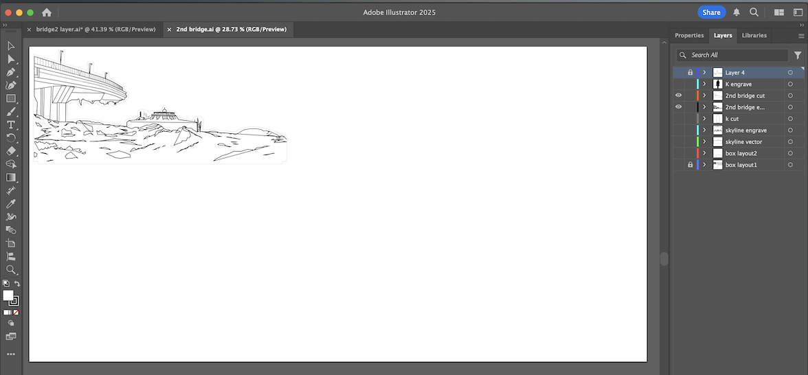
I have experience using the Adobe suite, as for my filmmaking work I edit in Premiere, edit stills in Photoshop, and now I am picking up Illustrator to create graphics. For a previous project where I created a laser-cut nightlight, I designed the graphics and exported them as .SVG files in Illustrator for the laser cutter.
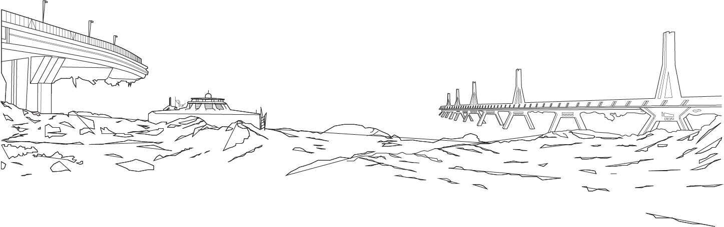
Here is a more completed version of my graphics.
3D Modelling in Fusion 360
I had never used Fushion 360 before, and the extent of my 3D modelling knowledge was introductory use of Blender for a school project eons ago and TinkerCad which is much more simple. I knew it would be a challenge to learn this new program and I can still safely assure you I am not an expert.
I began with a sketch and created the following image.
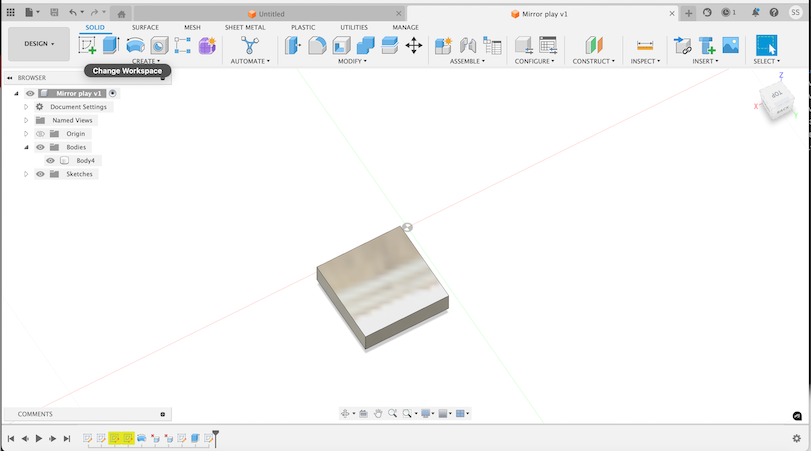
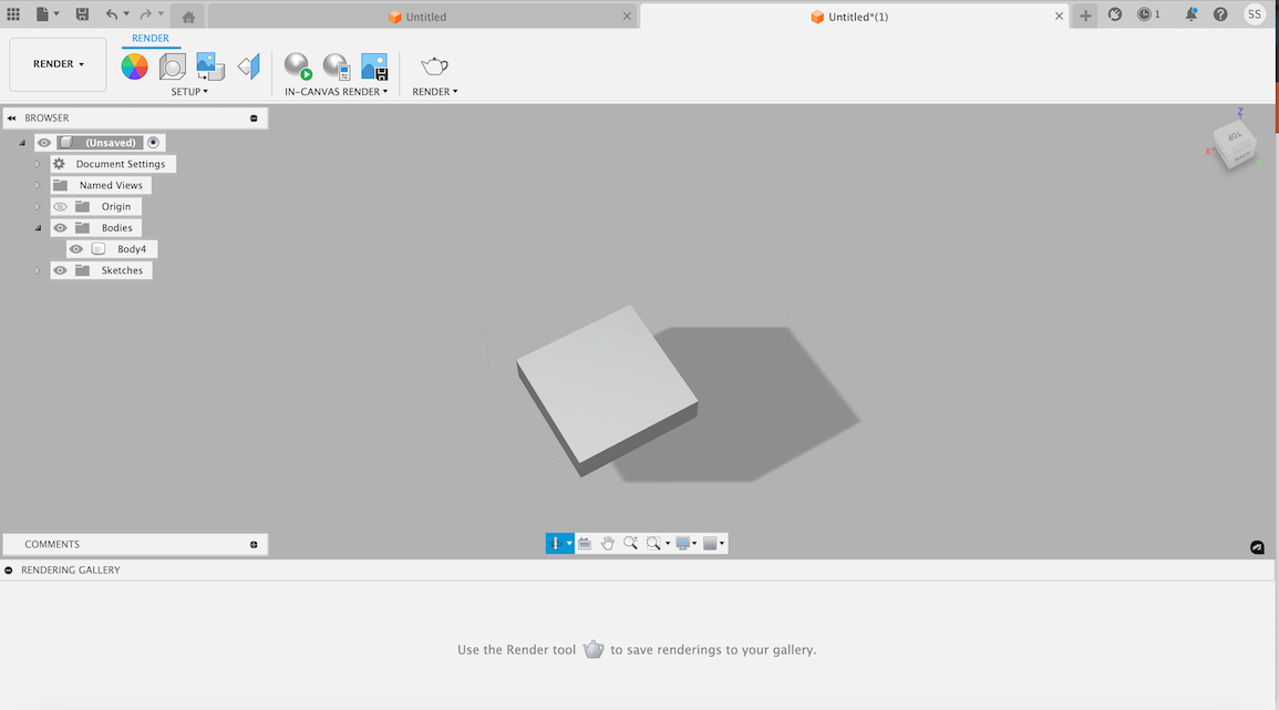
In the first image, I was working in Fusion 360’s Design workspace under Solid mode, where I created a 3D body that was meant to have a reflective or mirror-like surface. I started by sketching a basic rectangle and then extruding it into a 3D shape. To make it look more like a mirror, I experimented with applying materials and appearances. The left-side browser panel shows the structure of my project, including the bodies, sketches, and the origin. The toolbar at the top gave me options to modify and refine my design as needed.
After I felt comfortable with this design, I attempted to render my design to see what it would look like in real life.
In the second image, I switched to the Render workspace to get a more realistic visualization of my model. Here, the object appears smoother, with lighting and shadows making it look more like a physical object. The neutral gray background is part of the default rendering setup. To get to this step, I selected the Render workspace, applied or refined the material to enhance the reflective effect, and used the In-Canvas Render tool to preview how light interacts with the surface. I also adjusted some lighting and environment settings to make it look more realistic. This step helped me better understand how my design would look in real-world conditions.