Week 7: Computer Controlled Machining
Group Assignment
This week's group assignment was to do the safety training and test some characterstics of our lab's machine. The link the to the group documentation is here. Wheaton Fab Lab has an Axiom Precision CNC machine that we used for this week.
I learned a lot about CNC machines this week. While I had a general idea of how they worked, I had never used one before. I was almost surprised by how many things could go wrong that could cause damage to the operator or the machine. Though safety is always important, there was a lot more to go over this week. One specific thing I found interesting was upcut versus downcut end mills. Upcut end mills force debris upwards and downcut end mills force debris underneath the material. I wouldn’t have thought about the effects of which way the debris is removed, let alone there were different tools for different situations.
Design
For this week, I tried to make an A-frame birdhouse. I once again used Autodesk Fusion for designing this week’s project. I won’t be going over all of the tools that I used in weeks 2, 3, and 5.
Change the Document's Units
Sketch of Bottom
Sketch of Front Side
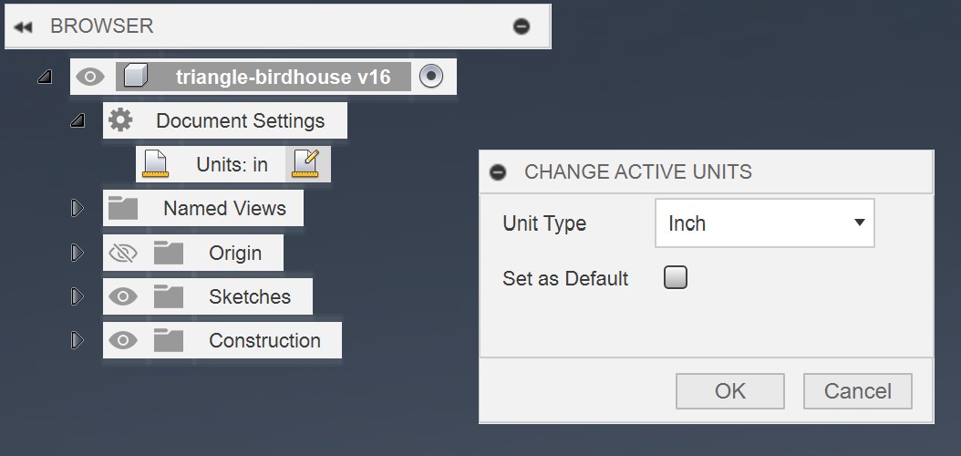
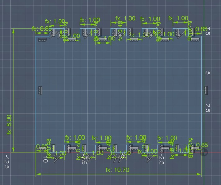
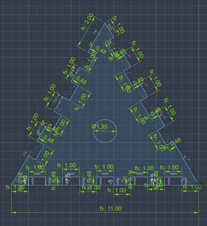
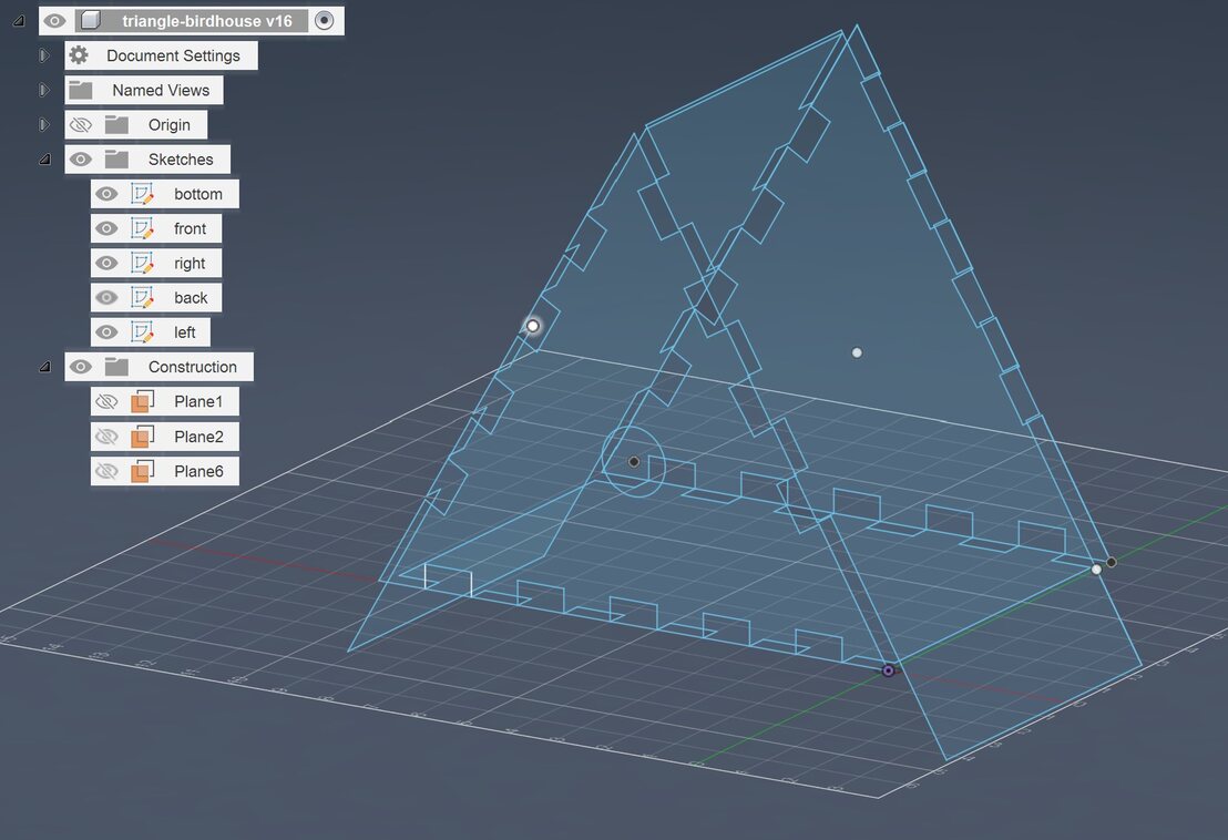
Before sketching, I changed the document’s scale to inches by going to Document Settings -> Units. I started out by making a rectangle sketch for the bottom of the birdhouse. I then made 6 evenly spaced slots on the long sides of the rectangle that the front and back could fit into. The depth of the slots was supposed to be the thickness of the wood. All of the measurements are parameters since I wasn’t sure how large I wanted things to be when I started the design. Next, I used the edge polygon tool, under Create -> Polygon -> Edge Polygon, to create a triangle. I then created slots on all three sides of the triangle to connect to the bottom and sides of the birdhouse. For the bottom slots, I had a pattern to follow because I had already designed the bottom piece. You may notice the slots on the left and right edges alternate with each other. This was so there wasn’t a thin piece at the top of the triangle between two slots. To make the back piece, I made a new plane using Construct -> Offset plane. This plane was 8 inches back from the front plane so I could easily place the back plane. I then pasted the front sketch onto the back plane. Going back to the front plane, I added a circle in the center of the triangle that would be the entrance to the birdhouse.
Angled Plane
Sketch of Left Side
Sketch of Right Side
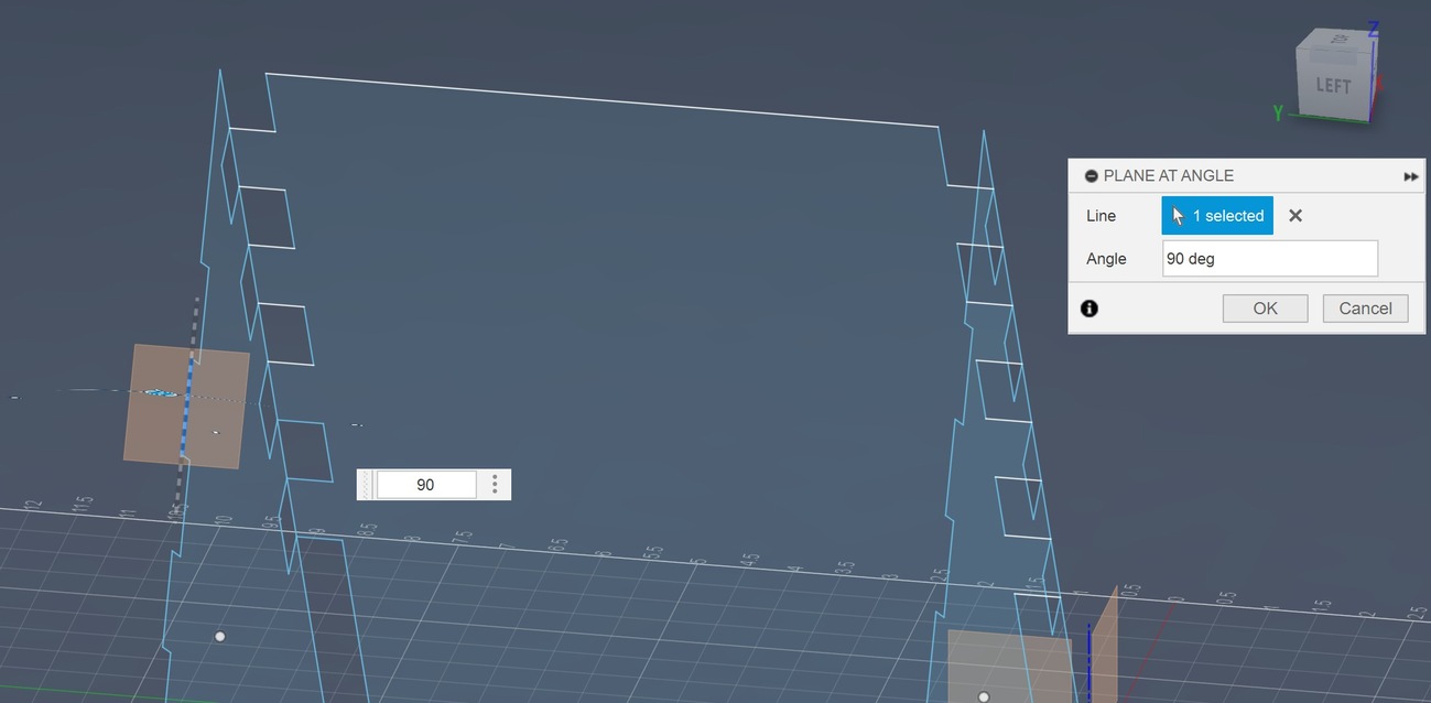
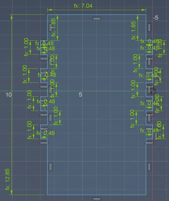
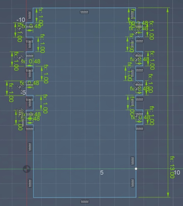
The left and right sides proved to be a bit trickier. I made an angled plane for each side by going to Construct -> Plane at Angle. In this tool, I selected a line on the side of one of the triangles. I then had to set the angle at 90 degrees so that the plane was perpendicular to the triangle. Because the plane is based on the side of the triangle, the side pieces will be at the same angle as the triangle. While this isn’t actually necessary for just designing pieces, I found it made it easier to visualize how everything would fit together. I then made a rectangle for each side of the triangle with slots that would fit into the slots on the front and back pieces. The rectangles have a thinner section at the bottom to fit between the front and back pieces. The left and right sides are a few inches longer than the birdhouse, the idea being that they could act as legs for the birdhouse. The left side is slightly shorter than the right side. This was to allow room for the left and right sides to come to a point. You may notice that the difference is smaller than the thickness of the wood. You may also notice I never extruded the sketches. I will come back to these points later.
Cutting Software
To prepare the design for the machine we used VCarve Pro. In our local lab time, we cut pieces to test different fits of slots. More information about that is in the group assignment. Some of the screenshots are from that session which is why there is a different design in some of the screenshots.
Job Setup
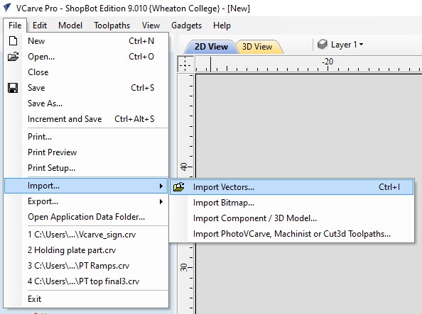
Import Vectors
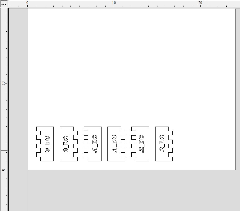
Example of Nicely Layed Out Vectors
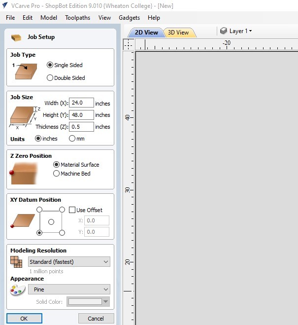
To get my files from Fusion to VCarve, I saved each sketch as a DXF and then used Adobe Illustrator to convert them to SVG files. This process is shown in my week 3 documentation under Parametric Design Construction Kit. When creating a new project in VCarve Pro, set your job size to the size of your material. For this, we had a 2’x4’ sheet of sande plywood. To add your SVG files, go to File -> Import -> Import Vectors. You will have to select your vectors one at a time. There are multiple ways to move your vectors around. You can select a vector by clicking on it and then using the arrow keys. You can also click on a vector twice and then click and drag the vector to where you want it. You can also select multiple vectors at once by clicking on an empty space and dragging a box around what you want to select. You want to space out your vectors so there’s about an inch between them. You also need to make sure that none of the designs go over the edge of the material or will overlap whatever you’re using to secure the material to the machine.
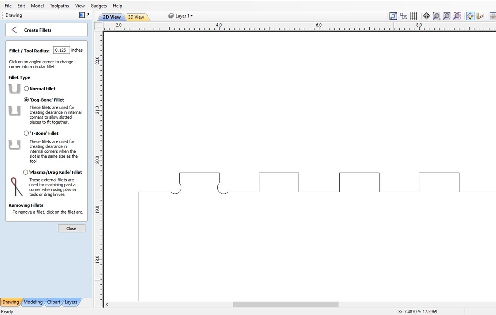
Add Dog Bone Fillets
Next up is to add dog bone fillets. Dog bones are a technique where a small circle is added on the inside corners of a part, allowing tight-fitting joints to work instead of the machine rounding the corners due to the end mill’s radius. Find the fillet tool on the left menu and select the Dog Bone option. I added dog bones to the inside corners of all of my parts.
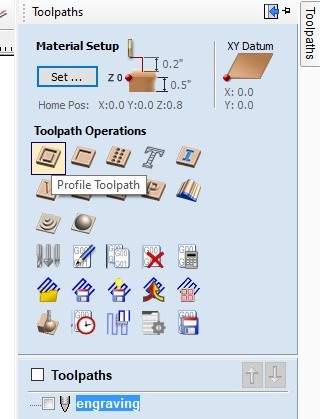
Selecting Type of Cut
Toolpath Settings
End Mill Settings
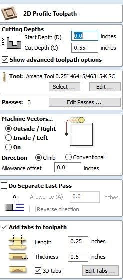
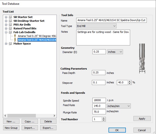
With the vectors complete, we can create the toolpaths that the machine will use to cut or engrave our piece. Select whatever vectors you want to be in the same toolpath. Go to the toolpath menu by clicking “Toolpaths” in the top right corner. I started with all of the outside cuts. To mark them as cuts, go to Material Selection and click Profile Toolpath. Names will appear if you hover over the symbols. Next, choose your end mill settings by going to Tool -> Edit under the toolpath menu. Select the endmill you plan on using and input your Spindle Speed and Feed Rate. You can find these settings by going to the manufacturer’s data sheet for the end mill. We used a 1/4” 46315-K Solid Carbide Spektra Upcut end mill. Here is a link to the data sheet. I set the cut depth to 0.55 inches to make sure it fully cuts through the 0.5 inch material. The machine vector is set to the outside of the vector so it doesn’t reduce the intended size of the pieces. Once you have set everything, hit OK to return to the toolpaths menu.
Tab Menu
Added Tabs
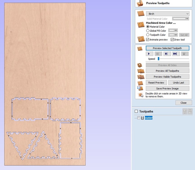
3D View of Toolpath
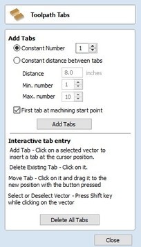
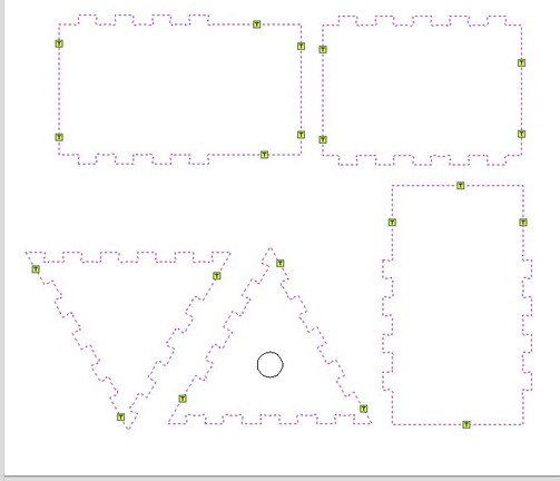
Before completing the outer toolpath, you have to add tabs. Tabs are a small spot that the machine won’t cut that will keep the piece attached to the material so the cut piece won’t fly out while the machine is running. In the toolpath menu check “Add tabs to toolpath” and then Edit Tabs. Click on the location on the vector where you want a tab. You want to try to get a tab on each side of a shape, preferably on a long, flat stretch. If you place a tab in a spot you don’t want it DO NOT press ctrl-z to undo it. This will undo whatever your last edit was before you entered the toolpath menu. When you’re happy with the tabs, hit Close to return to the toolpaths menu.
You are now ready to complete your toolpath. Scroll down to the bottom of the toolpaths menu and hit Calculate. This will take you to the 3D view. Here, you can hit Preview Selected Toolpaths and press the play button to watch a simulation of the cut. You can also rename this toolpath by double clicking on the path’s name under Toolpaths. You can then create more toolpaths by clicking on the 2D View button in the top left.
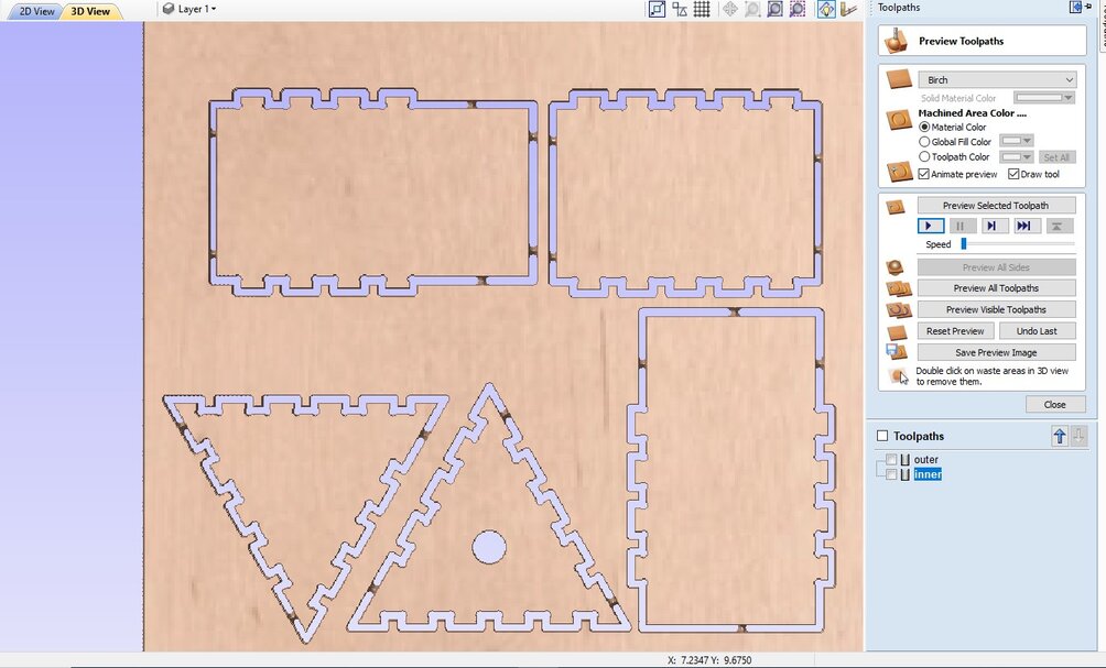
Inner Cutting Path Preview
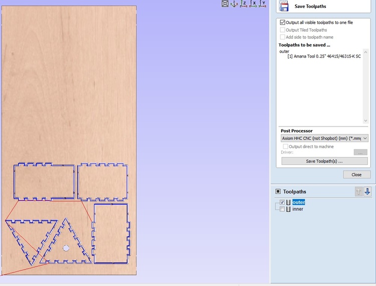
Save Toolpaths
I only had two toolpaths, one for the outer cuts and one for the circle cutout. To create the toolpath for the circle, I started by selecting the circle and going to the toolpaths menu. In Material Selection, I selected the option in the second column in the first row. This would engrave the circle into the material a few times until it completely cuts through. We did it this way because tabs are difficult to get off of rounded edges. I did not have to change the endmill settings because we used the same one as the profile cut. I can then Calculate and preview the path to cut out the circle. Once you’ve created all of your toolpaths, you can save them in the 3D view menu. When saving the toolpath make sure you only select one path, and then hit Save Toolpath(s). You want to save each path individually so you can select which order they go in and easily change the end mill in between cuts if need be. With this, put your saved toolpaths on a USB and you’re ready to cut!
Machining & Assembling
We are finally ready to use the CNC machine! I used 1/2” sande plywood for constructing my birdhouse. I want to shout-out/thank Brandon, who is one of my local instructors, for the help this week. Unrelated to Fab Academy, I injured my thumb and was having issues with two-handed activities so I greatly appreciated the help with setting up the machine! Of course, that was on top of him supervising and making sure that all safety precautions were followed.
Using the CNC Machine
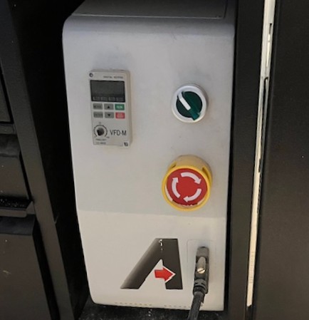
On Button
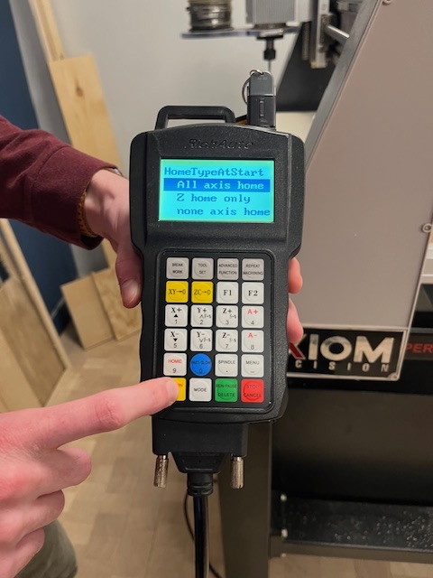
Home Machine on Startup
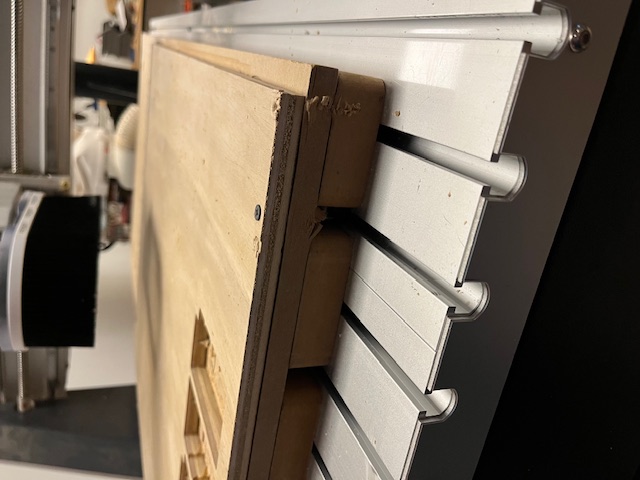
Screw Plywood to Spoilboard
A good place to start is turning on the machine. The power button is a green button on the side of the machine. There is a controller that is attached to the machine with a place to plug in a USB on top of it, so plug in the USB with your toolpath files. Once the machine is on, it will ask you if you want to home the machine. Select “All axis home” using the yellow OK button in the bottom left corner. Next you can attach your material to the machine. We drilled screws into each corner of the plywood and spoilboard to hold the plywood in place. You want to turn the machine on before this so that you can move the cutting head out of the way.
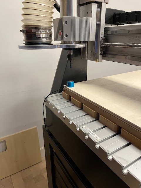
Alignment
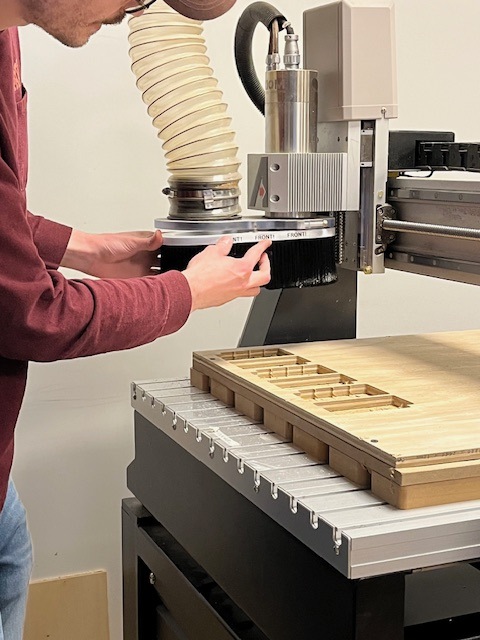
Attach Brush
Next up, you want to change the end mill. To do this, put two wrenches on different parts of the collet and push them towards each other to loosen it. You don’t have to take the collet off, you just have to loosen it enough to pull the end mill out. You can then insert whatever end mill you want to use and now push the wrenches in the opposite direction. Make sure the collet is on as tight as possible. Then you want to align the machine. There’s a little metal platform with a cord attached which can be plugged into the back of the machine. Next, set the little platform on top of your material. Then use the X+, X-, Y+, and Y- buttons to move the mill over the platform. Once you think it’s centered, press the Tool Set button. This will make the cutting head go down until it hits the metal platform. You can then remove and unplug the platform. You can add the brush attachment to the end of the cutting head, it attaches magnetically. This is so that the vacuum can suck up as much dust as possible.
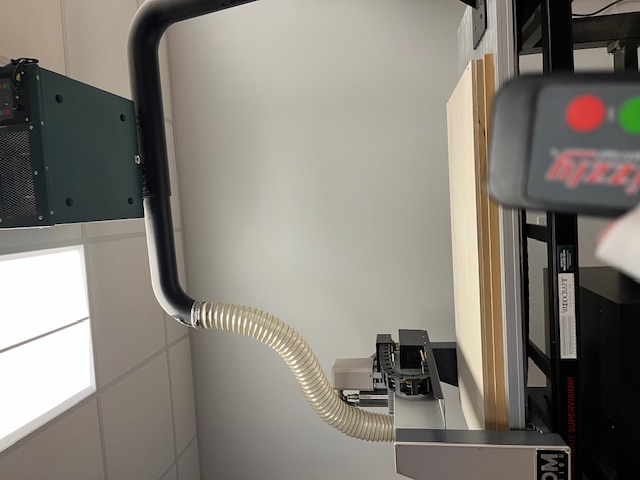
Turn On Air Filter
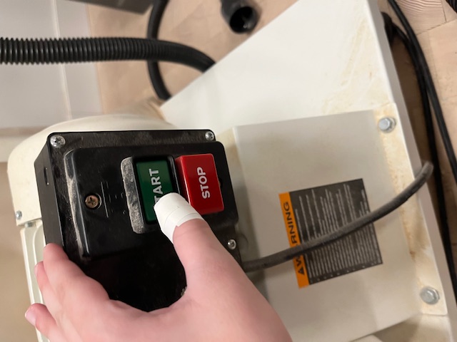
Turn On Vacuum
Before starting the cut, you need to turn on the vacuum and filter. The filter is turned on with a remote and is above the CNC machine. The vacuum is to the right of the CNC machine and has the buttons on the bottom. You’ll likely want to put on eye and ear protection before turning on the vacuum since it is quite loud.
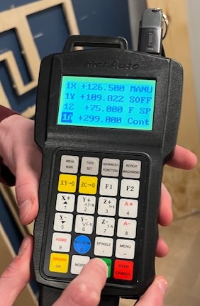
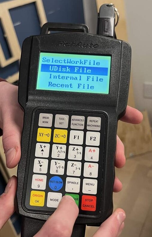
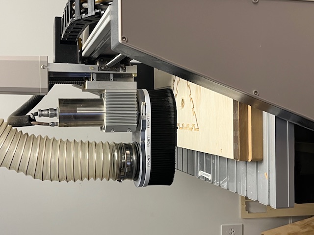
Mid-Cut
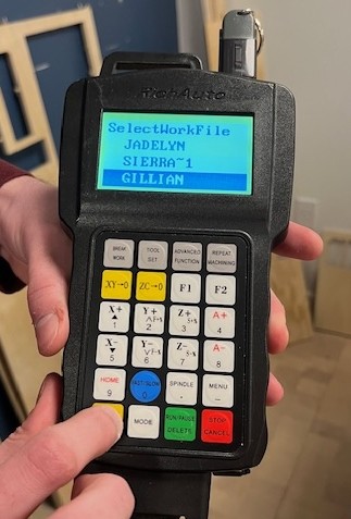
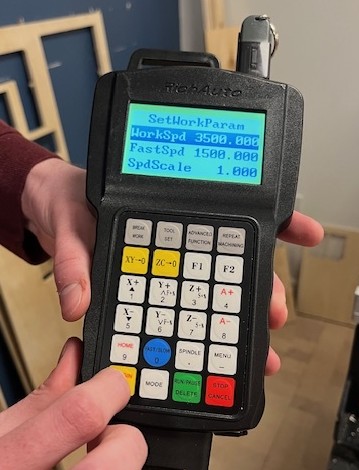
To start the machine, click on the green button. Then select UDisk File with the green button. Using the X+ and X- buttons, scroll to find your files in the USB drive. Hit the yellow OK button to select any folders and then your desired file. It will then show the parameters you set and you can click the yellow OK button again. It will then display a 5 second cutdown and start the cut. Do not stand super close to the machine whilst it is cutting and stay alert for any weird sounds or smells.
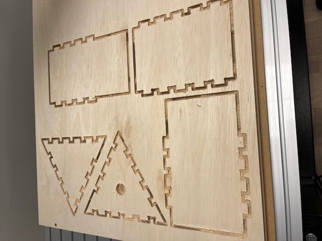
Cut Pieces
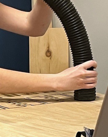
Vacuum Dust and Debris
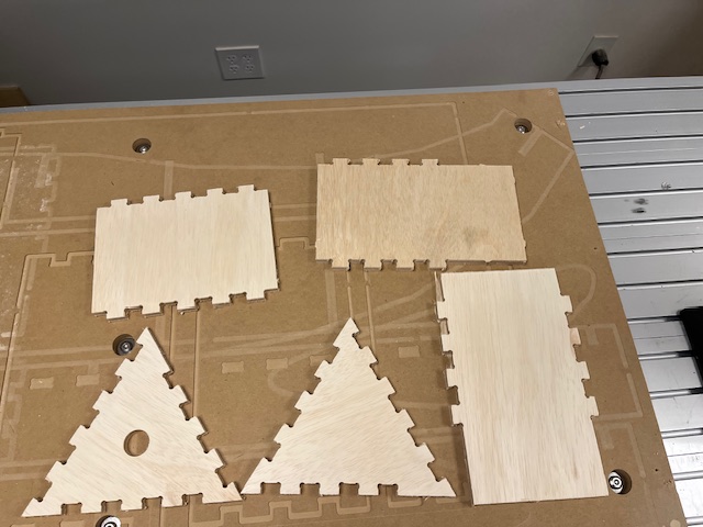
Removed Pieces
Once you have finished cutting all of your paths, you can vacuum the dust and debris off. Optionally, you can sand the tops of your pieces before removing the tabs. Once you’re ready, you can remove the tabs using an oscillating tool. You can then remove the screws used to secure the plywood to the spoilboard and remove the remaining plywood.
Assembly
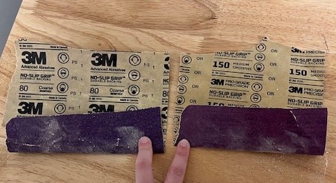
Types of Sandpaper Used
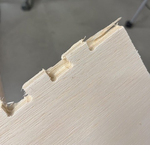
Onion Skin
Sanded Pieces
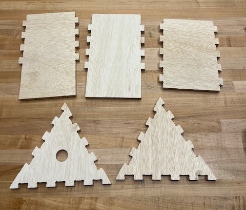
I spent some time sanding pieces so that all of the edges were smooth. I did most of the sanding with 80 grit sandpaper and then finished them off with 150 grit sandpaper. One piece had a bit of onion skinning, which is when a thin bit of material is stuck to the bottom of a piece. I was able to take off the bigger pieces with my hands, but you could use an exacto knife as well. It was unnoticeable once I had sanded down the sides.
Front of Birdhouse
Back of Birdhouse
Shelf?
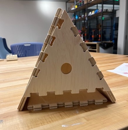
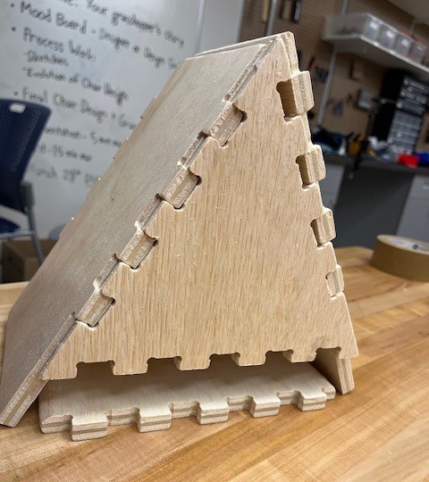
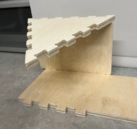
As you can see from the final pictures above, my design did not work. I did not leave enough room for the left and right sides to both come to a point at the top. I also didn’t leave enough room for the left and right pieces to go past the bottom piece so that they could be legs. If I had extruded the pieces in Fusion, I likely would’ve noticed these mistakes. Unfortunately, I did not have time to recut pieces because it is spring break this week.
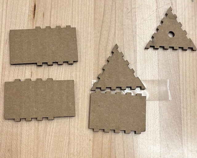
Pieces of Cardboard Birdhouse
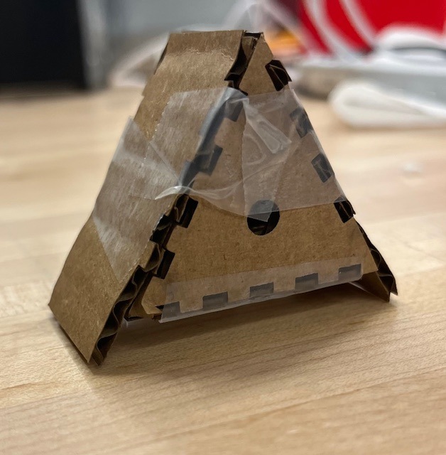
Cardboard Birdhouse
To fix this design, I reduced the height difference in the left side by a bit over the thickness of the wood. I also reduced the length of the bottom piece by the thickness*2 so that both the left and right sides could easily pass by and touch the floor. To test this, I laser cut a scaled down version of the birdhouse out of cardboard using the same method as week 3. I should have done that to begin with but I have to learn my lesson somehow. I believe at full scale my design would work, though I can just trim my original one some I’m not going to make a whole new wooden one. The cardboard one is taped together because the cardboard tabs are not very strong since it’s small pieces of cardboard.