Week 4: Embedded Programming
Group Assignment
This week's group assignment was about using different toolchains and microcontrollers. My group's documentation is here.
Individual Assignment
Learning Wokwi
Starting a Project
I used Wokwi to simulate the code and circuits this week. I decided to try out the Raspberry Pi Pico microcontroller because I would be more likely to use it since it’s a lot smaller than the Arduino Uno. The first thing I did is click the “Pi Pico” option, which is the left image. I then choose the leftmost option under Starter Templates, which is just labeled Pi Pico. I chose this option because I wanted to do the program in C++. The rightmost option allows you to program in Python. I did also reference the datasheet for the Raspberry Pi Pico. Even though I don’t fully understand it, the pinout diagram was helpful. I used it to see what pins were ground or had other special functions.
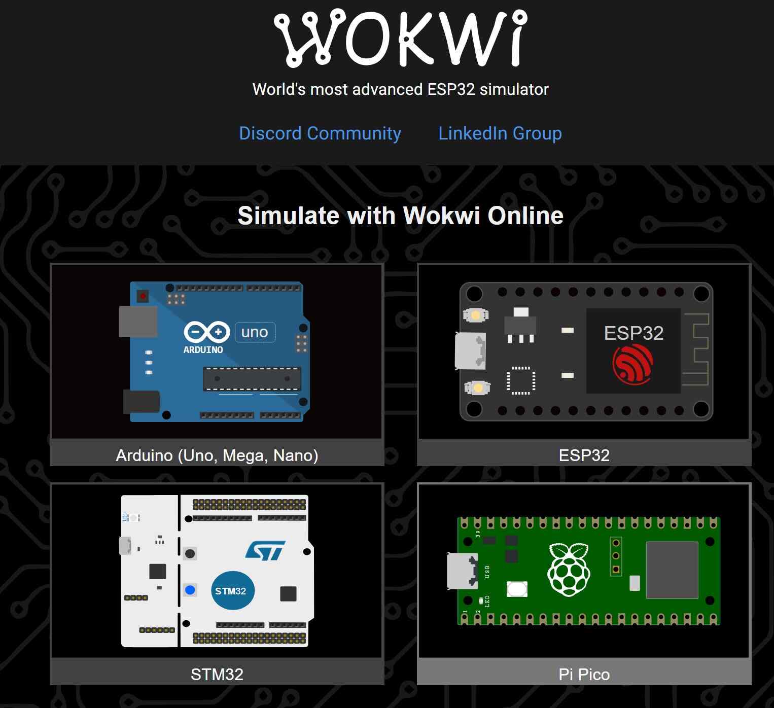
Wokwi Home Page
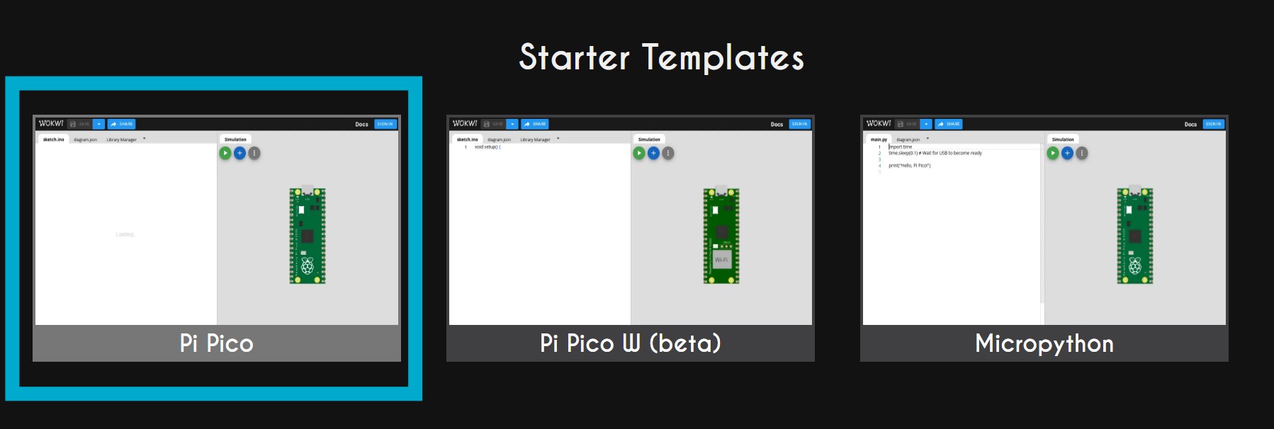
Select Type of New Project
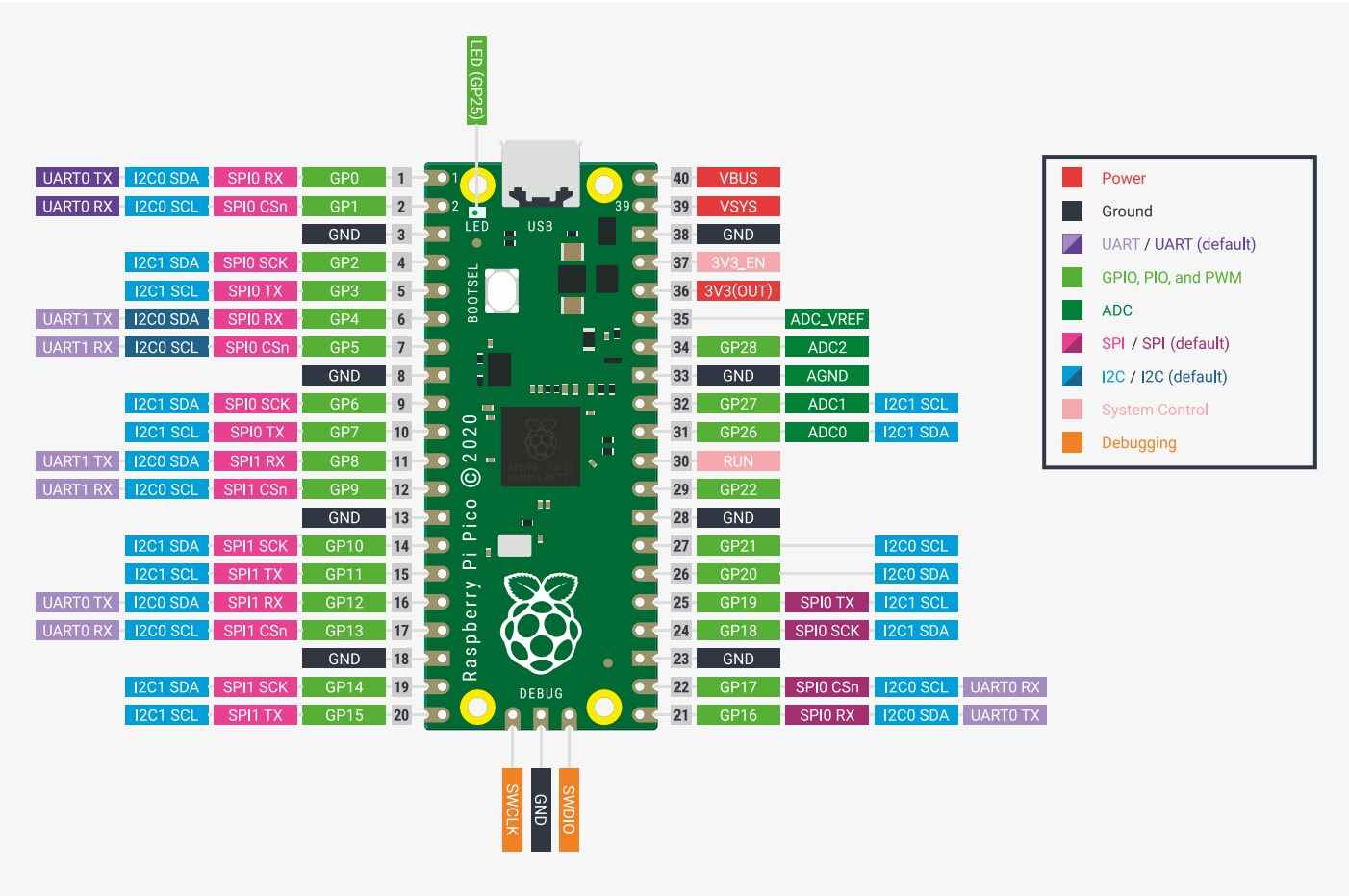
Pinout of the Raspberry Pi Pico
One feature I have found extremely helpful overall is that there are explanations for most of the components. When you click on a component, frequently a question mark will appear near it. If you click on the question mark, you can see a diagram reference for that part. There is also a question mark with the same function in the header that pops up. You can also just go to the target site itself.

Flashing LED
The first thing I tried to do on Wokwi was make an LED flash, since that is what we did as part of the group assignment.
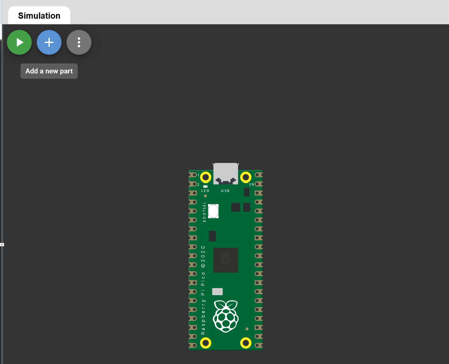
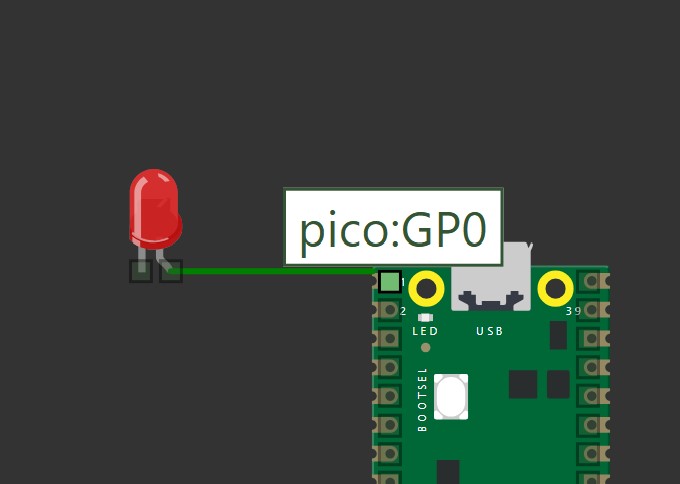
To start, I added an LED and resistor to the simulation. On the simulation half of the page, the plus sign allows you to add components. To add wires between components, click on one of the pins then click on the other pin you want to connect the first to. You can also click on empty spots to “anchor” your wire there so you are able to organize it. You can also change the color of the wire by clicking on a completed wire then choosing your color from the header menu. Black wire is usually ground, which is something I’ve tried to stick to. The LED is connected to pin 0 and ground in this example.
I also had to set the resistor to 220 ohms. To do this, I clicked on the resistor once in the simulator. I was then able to input the amount of ohms, make sure to specify ohms, kilo ohms, or mega ohms. You can also rotate the direction of the resistor using the circle arrow button next to the ohm settings.
Add Components to the Circuit
Wire Pieces Together
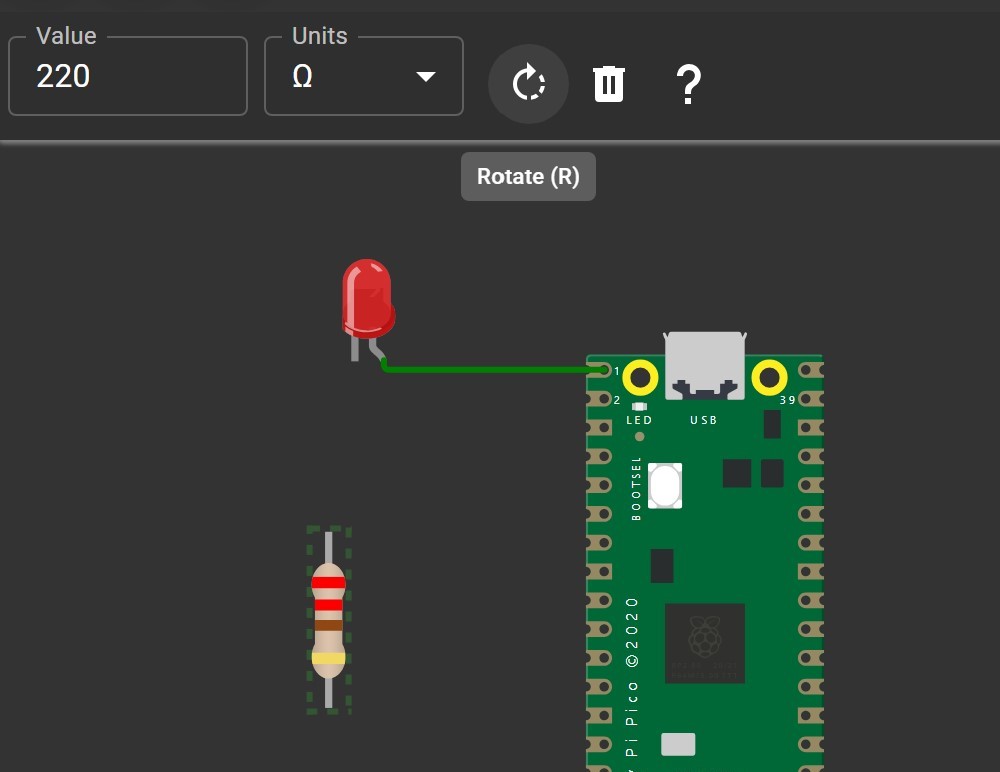
Edit The Resistor
I then needed some code to actually make the light blink. In setup, I made sure to set the output pin to 0, since that is what the LED is connected to. Otherwise, this is almost the exact same code I used in the group assignment.
        void setup() {
          pinMode(0, OUTPUT); //output for LED
        }

        void loop() {
          digitalWrite(0,HIGH); //turn on LED
          delay(1000); //wait 1 second
          digitalWrite(0,LOW); //turn off LED
          delay(1000); //wait 1 second
        }
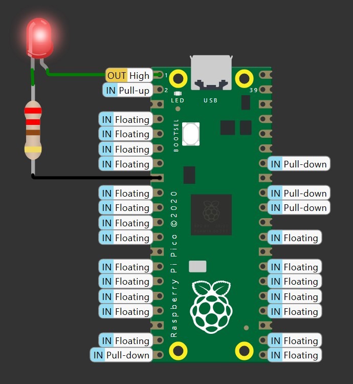
With both the circuit and code complete, I was able to run the simulator by clicking the play button in the top left corner of the simulation window.
Using a Button
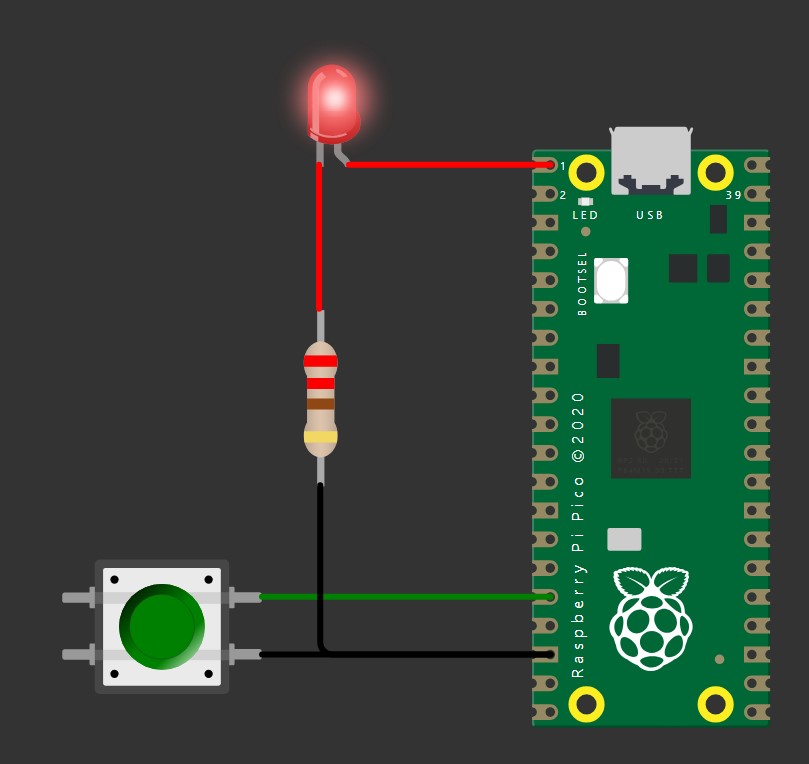
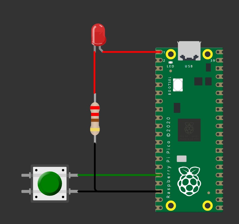
My next goal was to get some outside input. I decided to start with the push button. As you can see below, the circuit turns on the LED when the button is being held. For this I used the Push Button Reference for wiring reference and an example button circuit for a code reference.
Wiring wise, this is not much more complicated than the last circuit. I started by adding a push button to the circuit from the previous section. I then connected the 1.r button pin to pin 12 on the board. This will serve as the input. I then connected button pin 2.r to one of the ground pins on the board. The important part to remember when connecting pins is that 1.l and 1.r are always connected and 2.l and 2.r are always connected. This means one of the 1 or 2 pins needs to be connected to get input and the other should be connected to ground.
Button Being Pressed
Button Not Being Pressed
The code was the harder part of this circuit. In setup, I set pin 12 to INPUT_PULLUP. I tried just plain INPUT and that did not work. We start by reading the input of pin 12, where the button is, into an integer variable. If the button’s state changes in the middle of the if-else it won’t matter because we are checking the variable. The main part of the loop is an if-else statement to check whether the button is being pressed. An important note is that the button will output LOW when it is being pressed and HIGH when it isn’t being pressed. At the end there is a delay because it was in the Arduino Uno Button example I referenced. It seems to make the transition of the LED turning on and off smoother.
        void setup() {
          pinMode(0, OUTPUT);
          pinMode(12, INPUT_PULLUP);
        }

        void loop(){
          int button = digitalRead(12);

          if(button == LOW){
            digitalWrite(0, HIGH);
          }
          else{
            digitalWrite(0, LOW);
          }

          // Slow down the sketch.
          // Also for debouncing the button.
          delay(100);
        }
Mulitple Inputs and Outputs
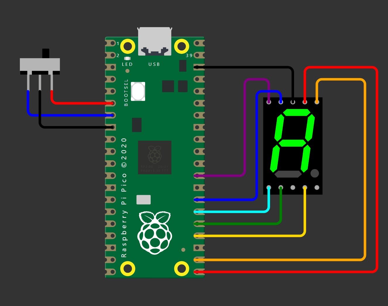
For my more complicated circuit I decided to try to use a 7 segment display. The 7 segment display tells you whether the slide switch is in the left or right position. When the switch is on the left, an L is displayed. When the switch is on the right, (something that sort of looks like) an R is displayed. I used the Wokwi reference pages for both the 7 segment display and the slide switch. There are code snippets on both of these pages that I used pieces of.
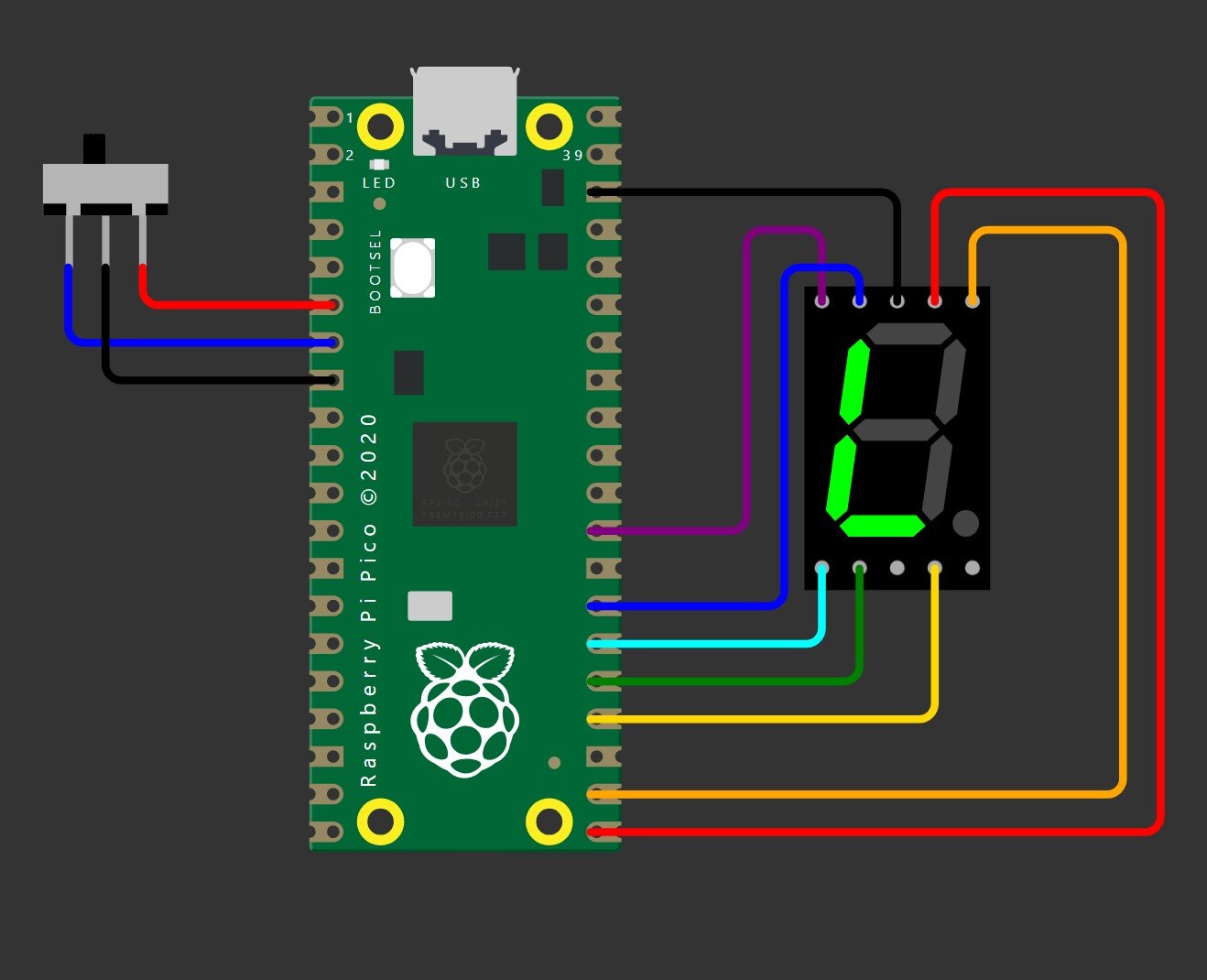
Switch on the Left Side
Switch on the Right Side
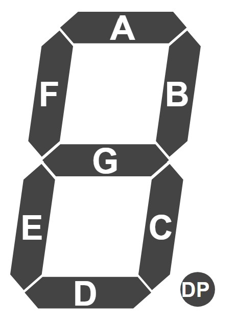
Letters Corresponding to Each Segement
7 Segment Display
I started by wiring up the 7 segment display. The common pin is a cathode and goes to ground. Seven of the pins correspond to each segment in the display. Each segment has its own letter, which is the rightmost image above. I enabled all seven of the pins for output. To test to see if I did it correctly, I ran the below code. I then changed out the 16 in digitalWrite to test out each pin/segment individually.
        void setup() {
          pinMode(16, OUTPUT); //segment A
          pinMode(17, OUTPUT); //segment B
          pinMode(18, OUTPUT); //segment C
          pinMode(19, OUTPUT); //segment D
          pinMode(20, OUTPUT); //segment E
          pinMode(21, OUTPUT); //segment F
          pinMode(22, OUTPUT); //segment G

          digitalWrite(16, HIGH);
        }
Final Circuit
After I knew the display worked, I hooked up the sliding switch. The left and right pins correspond to where the switch is. If a switch is on the right, then the right is going to equal low, not high. The middle pin goes to ground. I set those pins to be able to take input, which is the same as the button. As for the logic, I checked if the right pin was low which would correspond to displaying an R. If the right pin wasn’t low, that means the switch was on the left and it should display an L. The words “left” and “right” are also printed on the serial screen depending on the switch position. It prints every time the program goes through the loop function.
As for displaying the letters, I manually turned on and off each segment to make an L or R. I would be unsuprised if there is a more efficient way to do it, but this does consistently work. I used the letter chart above to determine which segments to turn on. I am aware that the R is a bit janky since 7-segment displays aren’t used for letters, but it does the job. I also kept the delay(100) from the last circuit to keep everything running a little bit smoother.
        void setup() {
          //for printing
          Serial1.begin(115200);

          //slide switch
          pinMode(4, INPUT_PULLUP); //right
          pinMode(5, INPUT_PULLUP); //left

          //7 Segment Display
          pinMode(16, OUTPUT); //segment A
          pinMode(17, OUTPUT); //segment B
          pinMode(18, OUTPUT); //segment C
          pinMode(19, OUTPUT); //segment D
          pinMode(20, OUTPUT); //segment E
          pinMode(21, OUTPUT); //segment F
          pinMode(22, OUTPUT); //segment G
        }

        void loop(){

          //right
          if(digitalRead(4) == LOW){
            Serial1.println("right");

            //turn on
            digitalWrite(16, HIGH); //A
            digitalWrite(17, HIGH); //B
            digitalWrite(18, HIGH); //C
            digitalWrite(20, HIGH); //E
            digitalWrite(21, HIGH); //F
            digitalWrite(22, HIGH); //G

            //turn off
            digitalWrite(19, LOW); //D
          }

          //left
          else{
            Serial1.println("left");

            //turn on
            digitalWrite(19, HIGH); //D
            digitalWrite(20, HIGH); //E
            digitalWrite(21, HIGH); //F

            //turn off
            digitalWrite(16, LOW); //A
            digitalWrite(17, LOW); //B
            digitalWrite(18, LOW); //C
            digitalWrite(22, LOW); //G
          }

          delay(100);
        }