This week I worked on adding a LCD monitor display to my board. I also had to make a new board as my current one didn't work with most Output Devices, due to it's lack of a TX and RX pin header.
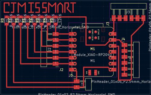
You can find my schematic and PCB here.
Group Assignment
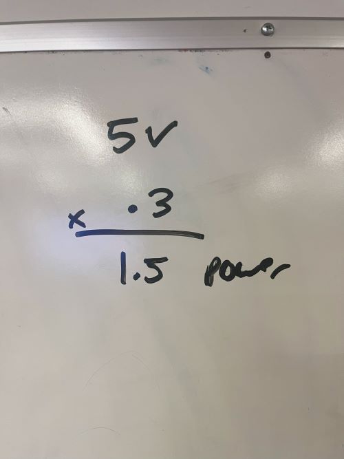
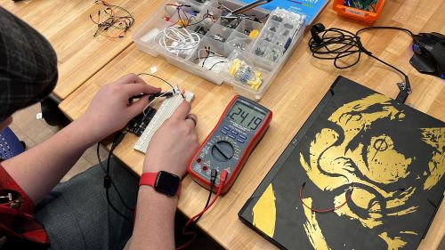
This week we learned about Output devices, which include things like neo-pixels and LCD monitors. An output device is a device that receives data from a computer and converts it into a form that can be understood by humans. For example, a monitor receives data from a computer and displays it on the screen, while a buzzer recieves an electrical signal and converts it into sound. This week we measured power consumption, which can be done using a multimeter and using some special calculations. The formula for power is P = V * I, where P is power in watts, V is voltage in volts, and I is current in amps.
Process for Coding Circuit Board
I had a lot of help with coding this again week, as I had help from online sources and my instructors as well as ChatGPT. You can find a link to my ChatGPT conversation here. However, I will go again and explain how my code works like I did last week.

I will also explain how each code line works here.
            #include <Wire.h>  // Include the Wire library for I2C communication
                #include <LiquidCrystal_I2C.>  // Include the LiquidCrystal_I2C library for LCD control
This is our "communications" stage of the coding process, where we communicate that we want to use the "Wire" and "LiquidCrystal_I2C" libraries for our code. If we didn't do this, we wouldn't be able to use the functions in those libraries, and our code would simply not work.
LiquidCrystal_I2C lcd(0x27, 16, 2);
This is our I2C address, which tells our board where to send the data it recieves from the code. The "16" and "2" are the number of columns and rows on the LCD monitor, respectively.
            void setup() {
                // Start the I2C communication on the default pins (SDA and SCL)
                Wire.begin();  // No need to specify D4 and D5

                // Initialize the LCD
                lcd.begin(16, 2); // Set up the LCD's number of columns and rows

                // Turn on the LCD backlight
                lcd.backlight();
This is the start of our communications with the LCD monitor itself. "Wire.begin()" starts the I2C communication on the default pins, which are D4 and D5 on the XIAO RP2040. "lcd.begin(16, 2)" sets up the LCD's number of columns and rows, which we defined earlier. "lcd.backlight() turns on the LCD backlight, which is important for seeing the text on the screen.
            // Print a test message
            lcd.setCursor(0, 0); // Set cursor to the top-left corner
            lcd.print("Hello, XIAO!");

            lcd.setCursor(0, 1); // Set cursor to the second line
            lcd.print("I2C LCD Test");
          }
This code sets up our messages to be printed. "lcd.SetCursor(0, 0);" sets the cursor to the top left corner, and "lcd.print ("Hello, XIAO!")" prints out our message. "lcd.setCursor(0, 1)" sets the cursor to the second line, and "lcd.print("I2C LCD Test")" prints out our second message.
            void loop() {
                // Add functionality here if needed
                // For now, let's just add a small delay to keep the display running.
                delay(1000); // Wait for 1 second before refreshing the LCD
              }
This is the final stage of our code, the "void loop()", which loops our code so that it repeats, after a 1000ms delay.
            #include <Wire.h>  // Include the Wire library for I2C communication
                #include <LiquidCrystal_I2C.h>  // Include the LiquidCrystal_I2C library for LCD control

                // Initialize the LCD with the I2C address and screen size (16x2 in this case)
                LiquidCrystal_I2C lcd(0x27, 16, 2); // Change 0x27 to your LCD address if it's different

                void setup() {
                  // Start the I2C communication on the default pins (SDA and SCL)
                  Wire.begin();  // No need to specify D4 and D5

                  // Initialize the LCD
                  lcd.begin(16, 2); // Set up the LCD's number of columns and rows

                  // Turn on the LCD backlight
                  lcd.backlight();

                  // Print a test message
                  lcd.setCursor(0, 0); // Set cursor to the top-left corner
                  lcd.print("Hello, XIAO!");

                  lcd.setCursor(0, 1); // Set cursor to the second line
                  lcd.print("I2C LCD Test");
                }

                void loop() {
                  // Add functionality here if needed
                  // For now, let's just add a small delay to keep the display running.
                  delay(1000); // Wait for 1 second before refreshing the LCD
                }
This is the full code for the LCD Monitor
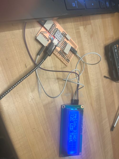
This is the final product of my LCD monitor, which displays the text "Hello, XIAO!" and "I2C LCD Test" on the screen.