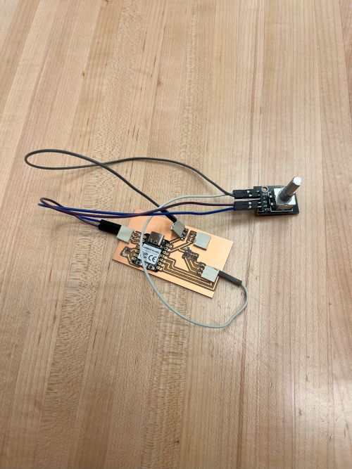
This week I worked on adding a rotary encoder to my board and coding it to brighten and dim a red LED as well as send out a message to the serial monitor.
Group Assignment
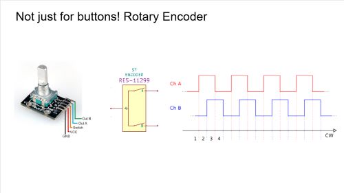
This week we learned about all kinds of different sensors such as thermistors, potentiometers, and more! We learned how each one operated and how to code them. We also learned about the different types of sensors, such as analog and digital sensors. We also learned about the different types of outputs, such as LEDs. We learned how to code them as well. In addition to learning about sensors, we also learned about pull up and pull down resistors, which pull electrical currents through them to ground or power. My favorite one was the Rotary Encoder because I figured that I could use it in my final project to control the power output of the electromagnet. A rotary encoder is an electromechanical device that converts the rotational motion of a shaft into electrical signals, providing information about the shaft's position, speed, and direction. It has two outputs, one for each direction of rotation. It also has a button that can be pressed to send a signal to the microcontroller. I thought that was pretty cool.


Process for Coding Circuit Board
I had a lot of help with coding this week, primarily from ChatGPT, which I used to get the base codefiles, which then had to be adapted to the XIAO RP2040. The most crucial adaptation was the pinout, which was different from the one in the base code. I had to change the pins to match the ones on the XIAO RP2040, which was easy to do. All I had to do was put a "D" in front of the pin number, and it worked perfectly. You can find a link to my ChatGPT conversation here.

I will also explain how each code line works here.
            #define CLK D0  // Clock pin
            #define DT D1   // Data pin
            #define LED D4  // LED pin (PWM)

            int lastStateCLK;
            int currentStateCLK;
            int ledBrightness = 0;  // LED brightness (0 - 255)
This is our "defining" stage of our code, where we define our variables. CLK and DT are pins on the Rotary Encoder, and LED is a pin on my board. "int lastStateCLK" and "int currentStateCLK" refer to the current state of the rotary encoder, i.e. is it being turned clockwise or counterclockwise? "int ledBrightness" is a variable that we will use to control the brightness of the LED
            void setup() {
                pinMode(CLK, INPUT_PULLUP);  // Set CLK as input with pull-up resistor
                pinMode(DT, INPUT_PULLUP);   // Set DT as input with pull-up resistor
                pinMode(LED, OUTPUT);        // Set LED pin as output

                Serial.begin(115200);  // Start serial monitor for debugging

                lastStateCLK = digitalRead(CLK);  // Read initial state of CLK
            }
This is our "setup" stage of our code, where we set up our pins. We set CLK and DT as inputs with pull-up resistors, and LED as an output. We also start the serial monitor for debugging purposes, and read the initial state of the CLK pin. It is crucial to remember to also set your serial monitor to 115200 as well otherwise it won't be able to read the code fast enough.
            void loop() {
                currentStateCLK = digitalRead(CLK);
This is our "loop" stage of our code, where we read the current state of the CLK pin.
if (currentStateCLK != lastStateCLK) {
This is an "if" statement, where we check if the current state of the CLK pin is different from the last state of the CLK pin.
            if (digitalRead(DT) != currentStateCLK) {
                ledBrightness += 10;  // Increase brightness
                if (ledBrightness > 255) ledBrightness = 255;  // Cap at 255
                Serial.println("Rotated Clockwise - Brightness: " + String(ledBrightness));
            } else {
                ledBrightness -= 10;  // Decrease brightness
                if (ledBrightness < 0) ledBrightness = 0;  // Cap at 0
                Serial.println("Rotated Counterclockwise - Brightness: " + String(ledBrightness));
            }
This is another "if" statement, where we check if the current state of the DT pin is different from the current state of the CLK pin. If it is, we increase the brightness of the LED by 10, and if it isn't, we decrease the brightness of the LED by 10. We also cap the brightness at 255 and 0 respectively.
            lastStateCLK = currentStateCLK;
        }
This line of code updates the "lastStateCLK" to become the "currentStateCLK" so that we can detect the next change. This is the end of our "if" statement.
            #define CLK D0  // Clock pin
            #define DT D1   // Data pin
            #define LED D4  // LED pin (PWM)

            int lastStateCLK;
            int currentStateCLK;
            int ledBrightness = 0;  // LED brightness (0 - 255)

            void setup() {
                pinMode(CLK, INPUT_PULLUP);
                pinMode(DT, INPUT_PULLUP);
                pinMode(LED, OUTPUT);

                Serial.begin(115200);

                lastStateCLK = digitalRead(CLK);  // Read initial state of CLK
            }

            void loop() {
                currentStateCLK = digitalRead(CLK);

                // Check if state changed
                if (currentStateCLK != lastStateCLK) {
                    if (digitalRead(DT) != currentStateCLK) {
                        ledBrightness += 10;  // Increase brightness
                        if (ledBrightness > 255) ledBrightness = 255;  // Cap at 255
                        Serial.println("Power INCREASED: Defensive Mode ACTIVATED" + String(ledBrightness));
                    } else {
                        ledBrightness -= 10;  // Decrease brightness
                        if (ledBrightness < 0) ledBrightness = 0;  // Cap at 0
                        Serial.println("Power DECREASED: Defensive Mode DEACTIVATED" + String(ledBrightness));
                    }

                    analogWrite(LED, ledBrightness);  // Update LED brightness
                }

                lastStateCLK = currentStateCLK;
            }
This is the full code for the rotary encoder. It is a simple code that increases and decreases the brightness of an LED based on the direction of the rotary encoder. It also sends a message to the serial monitor based on the direction of the rotary encoder. It is a simple code that is easy to understand and implement. You'll also notice that I added a few flavoring messages to my code. Since its going to be used on a shield, I thought it would be fun to make it say "Power INCREASED; Defensive mode ACTIVATED" and "Power DECREASED; Defensive Mode DEACTIVATED" on the serial monitor.