Group Assignment
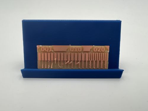
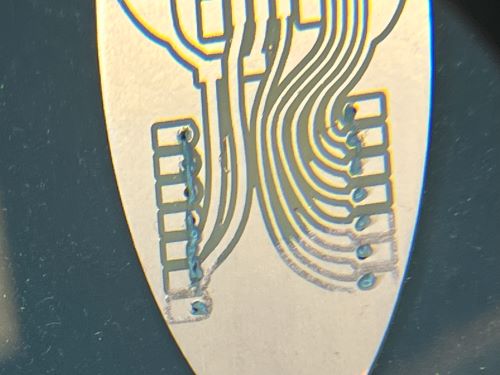
This week, we discussed design rules for Roland machining. The most important rule is that each trace must be at least 0.4mm apart from each other. This is because the Roland machine has a 0.4mm bit, and if the traces are too close together, the bit won't be able to cut them properly. Here you can see what happens when you don't follow this rule. You can automatically check your design rules in KiCad by going to the design rules check and selecting the "Design Rules" tab. Then, you can select the "Run DRC" button to check your design rules.

Process for Roland Machining
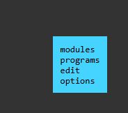
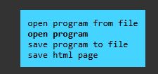
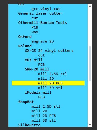
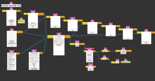
I started by taking my fancy board file from Week 6 and importing it to Mods CE as a PNG. To do this, I had to navigate the menu, which started by pressing right click to get the menu to appear. Then, I clicked on programs, and selected open program. Then, I scrolled down till I saw Roland, and clicked on "Mill 2d PCB"
Then I got this massive mess of stuff that made no sense to me. It was only after my instructor clarified what I was looking at that I could even begin to understand what I was doing.
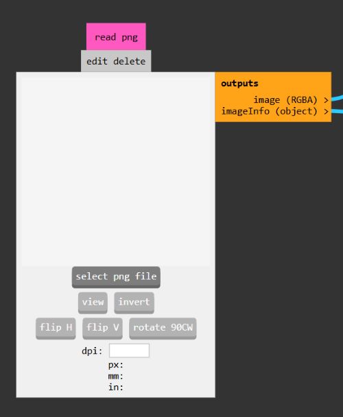
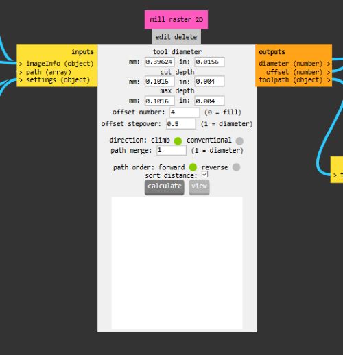
I clicked on my import PNG button. After that, I went ahead and set my milling machine speeds, which are as follows. I also turned off the WebUSB output button and turned on the Save File output button so that my file saved to my computer so I can upload it to the machine later.
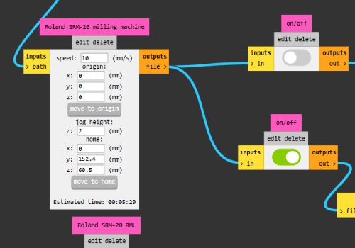
Then I rastered the PNG by pressing this calculate button.
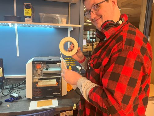
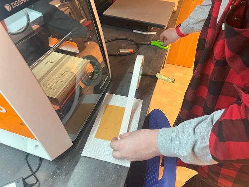
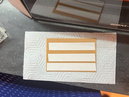
Then I downloaded it to a USB, and uploaded it to the machine. Then I got to work on the physical part. I first applied double sided tape.
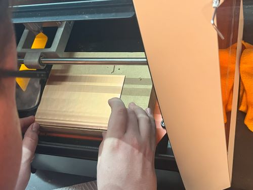
Then I placed the board on the table.
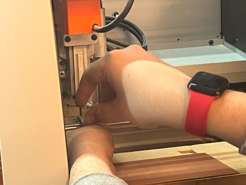
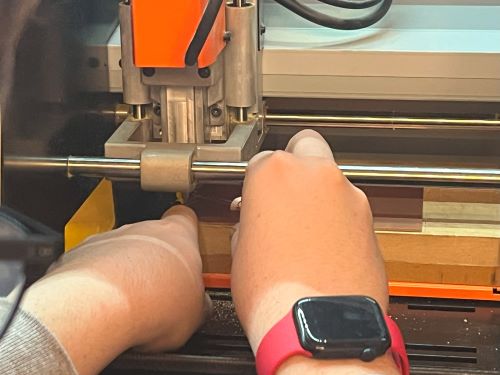
Then I had to change the bit and zero the board. In order to zero the board properly, you had to loosen the kollet a little bit, then push down on the board, then re-tighten the kollet so that its touching the board.
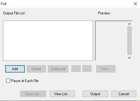
On the program, I added my Roland file using the "add file" button. Then I set my origin points.
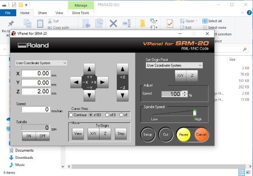
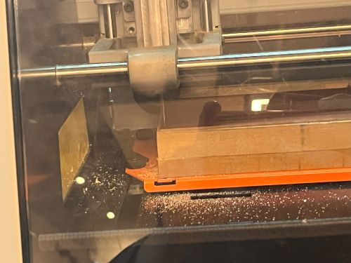
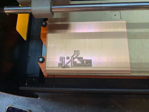
Then I ran the program, and it started cutting!
After that, I got started on soldering! I hadn't done it in a while so I first practiced on some dead boards.
Then, once I felt sure about it, I started soldering on my actual board. I first did my micronctroller, followed by my resistors and LED, and then I did the pin headers.
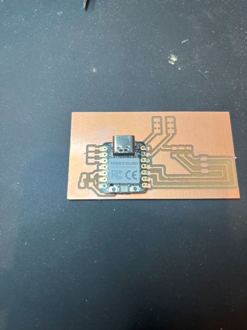
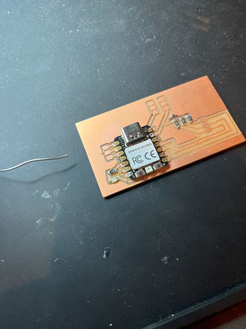
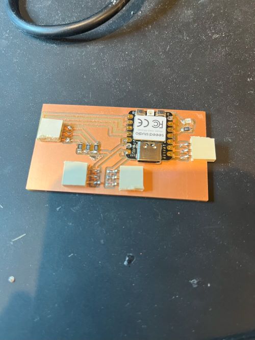
However, the keen eye may notice an issue with my board. I had a pin header blocking the microcontroller! "Egads!", I cried. However my instructor and I resolved to bend the pin upwards with pliers so that the microcontroller wouldn't be blocked.
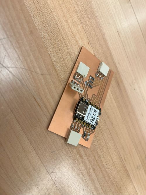
Time Travel
Here is a glimpse from a future assignment that shows my board working! Crazy stuff, right?