This week I worked on designing a basic circuit board and a more complex one that will serve as the start of the one I intend to use in my final project.
Group Assignment
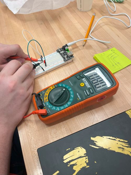
For our group assignment, we learned about how to measure electrical currents with multimeters and an osciloscope. We learned that a multimeter can be used not only to measure current, but can also be used to detect resistance by sending a small electrical charge through something, and can also create a sound to detect whether there is any current at all runing through the machine. Then, we got to work on using an osciloscope, which basically acts like a heart rate monitor to detect oscillating voltage. When you attach both ends of it to an electrical current, the osciloscope will show a heartbeat like wave that shows the oscillating voltage. The more the voltage oscilates, the shorter the distance will be between waves.
Research
I knew nothing about circuit boards for this week, so I paid very close attention to what my instructors were teaching us. I learned that a circuit board is basically just a sheet of copper tape. When you mill it on a machine, it will cut out the copper tape in the shape of your design, and then you can solder the components to the board. I also learned that the copper tape is actually a sandwich of copper, adhesive, and a protective layer. The adhesive is what sticks the copper to the board, and the protective layer is what keeps the copper from oxidizing.
Process for Circuit Board
I started by adding in the microcontroller. in order to do this, click on the add parts button on your toolbox. We will use this tool every time we want to add a new part to our board.
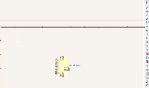

Next, I added in the LED. I did this by clicking on the add parts button again, and then searching for the LED in the search bar. I then clicked on the LED 1206 and added it to my board.

Then, I added in the resistor. I did this by clicking on the add parts button again, and then searching for the resistor in the search bar. I then clicked on the resistor 1206 and added it to my board.
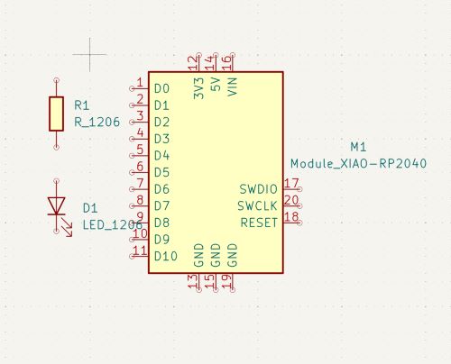
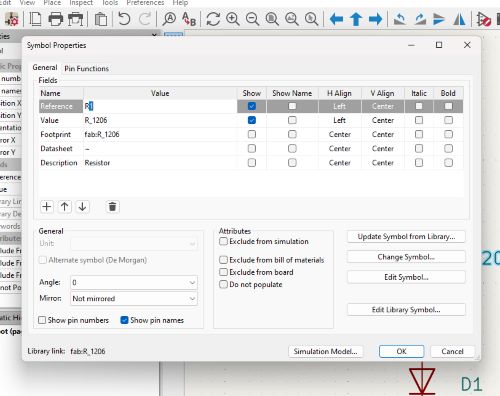
Then I clicked on the resistor, and changed the # of OHMS it has to 220. This is because the LED I added in earlier has a voltage of 220, so I need to make sure the resistor can handle that voltage.

Then I added the wiring and two GRND components. They act like portals straight to the ground pins of your circuit board. You can do this by clicking on the add wiring button here.

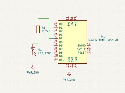
Then I switched to the PCB side of things with this button and uploaded my design. This will show you what your board will look like when it's milled.

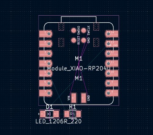
Then I clicked on the add route button to add routes. These are the paths the milling machine will leave untouched. I also set their diameters to .04 mm, so that they are large enough.

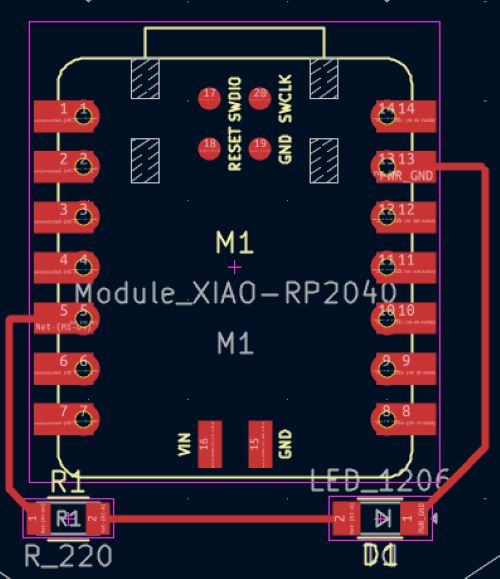
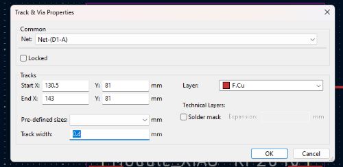
Then I clicked on the add outline button to add an outline. This is the path the milling machine will cut out
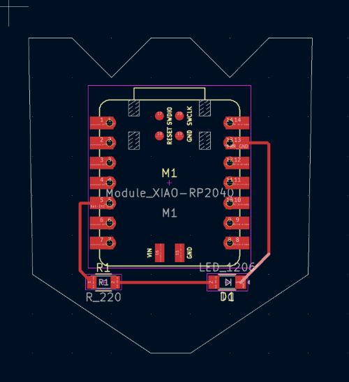
Then I saved the entire thing, and voila!
Fancy Board
Here is an image of my fancy board which will be used for general purpose, having several output pins, a few input pins, and a few GRND pins. I was having difficulty with the pathing routes, so I went into Route -> Interactive Router Settings -> Highlight Collisons, and then I allowed DRC Violations. This allowed me to see where the paths were overlapping and manually make the routes instead of relying on the system to do it for me. As for the pins, I used the same system to find them as I did the first time, by clicking on the add parts button and searching for them. I also added an LED with a resistor to use as a troubleshooting tool, so I could tell when electricity would be running in the board.
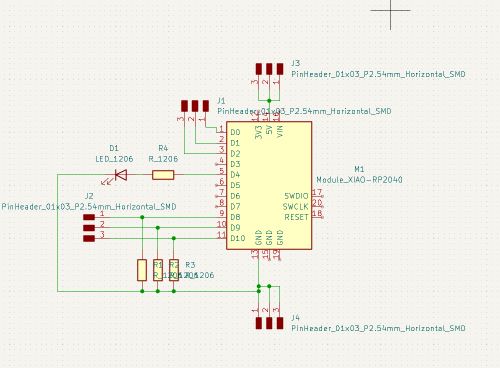
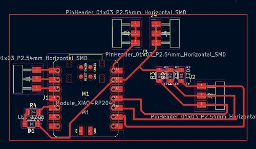
You can find my schematic and PCB here.