
About this week
This week, we learned about computer-controlled machining, focusing on creating 3D designs using software like SolidWorks and Fusion 360 and then machining them using a wood router. Before machining, we used VCarve Pro software to generate G-code from the design file, ensuring precise execution. Additionally, we received safety training on operating the wood router, understanding its functionality, precautions, and best practices to ensure smooth and secure usage. This helped us gain confidence in handling the machine effectively. Throughout the week, we worked on two assignments—a group assignment and an individual assignment—which allowed us to apply our learning practically. These tasks helped us improve our designing, toolpath generation, and machine operation skills in real-world scenarios. This experience provided valuable insights into digital fabrication techniques, reinforcing our understanding of CNC machining and its applications in prototyping and manufacturing.
Objctive of the Assignment
1.Gropu Assignment -
2. Indivisual Assignment -
About Computer Controlled Machining
Computer-Controlled Machining (CNC Machining) is a manufacturing process where computer programs control machine tools like routers, mills, lathes, and laser cutters. It allows for high precision, repeatability, and automation, making it essential for modern fabrication and prototyping. Using software like Fusion 360, SolidWorks or other software, designers create 3D models and convert them into G-code, which instructs the machine on cutting paths, depth, and speed. CNC machines can work with various materials, including wood, metal, plastic, and composites.
CNC WOOD ROUTER
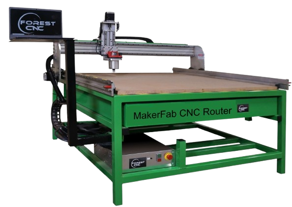
CNC (Computer Numerical Control) Wood Router is a machine designed for cutting, engraving, carving, and shaping wood with high precision and automation. Unlike manual wood routers, a CNC router is controlled by a computer, allowing for complex designs, faster production, and consistent accuracy.
 |
|
|
|
|
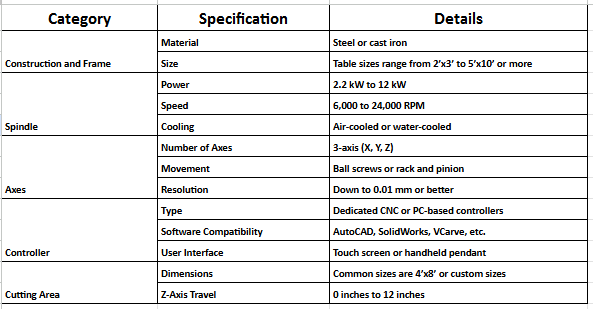
CNC Router Specifications
 |
|
|
|
|
Individual Assignment
3D Designing in Solid Work
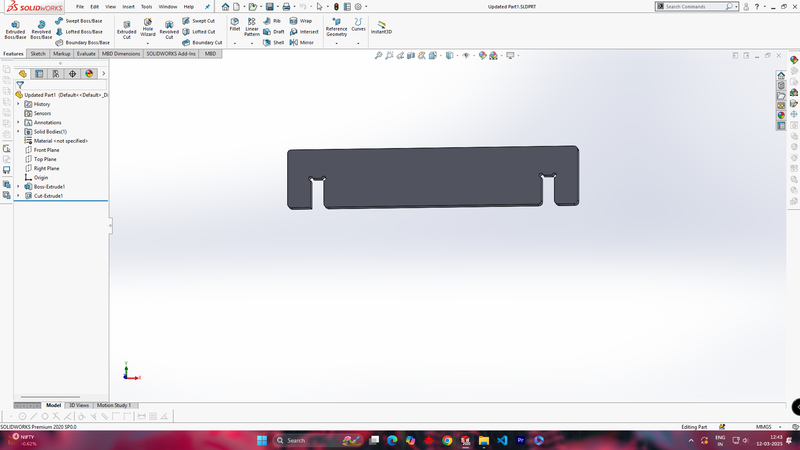
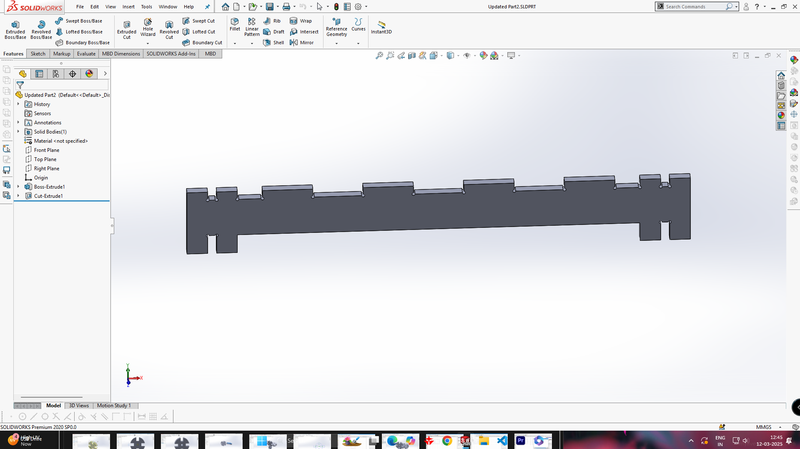
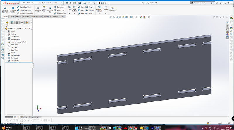
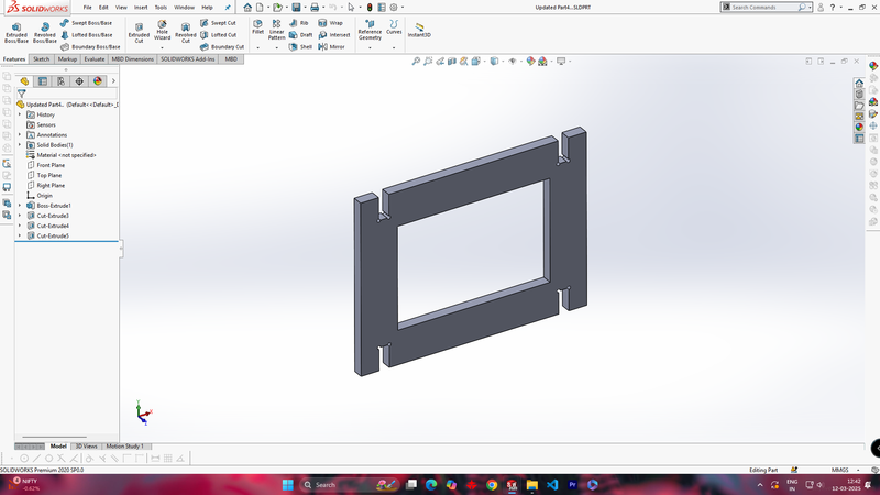
I used SolidWorks for 3D design and created a bookshelf, which was designed in four parts.
 |
 |
| Designing part 1 (Base Panel) |
Designing part 2 (Top side support Panel) |
 |
 |
| Designing part 3 (Back Panel) |
Designing part 4 (Front Frame Panel) |
 |
|
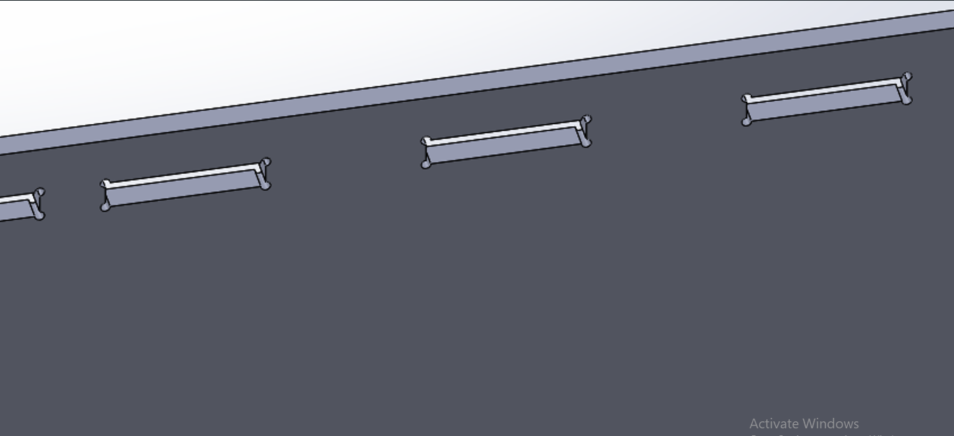
| In the all design, I have added a 3mm dog bone to each cut to ensure a smooth fitting during assembly after printing. |
|
3D Designing in Fusion 360
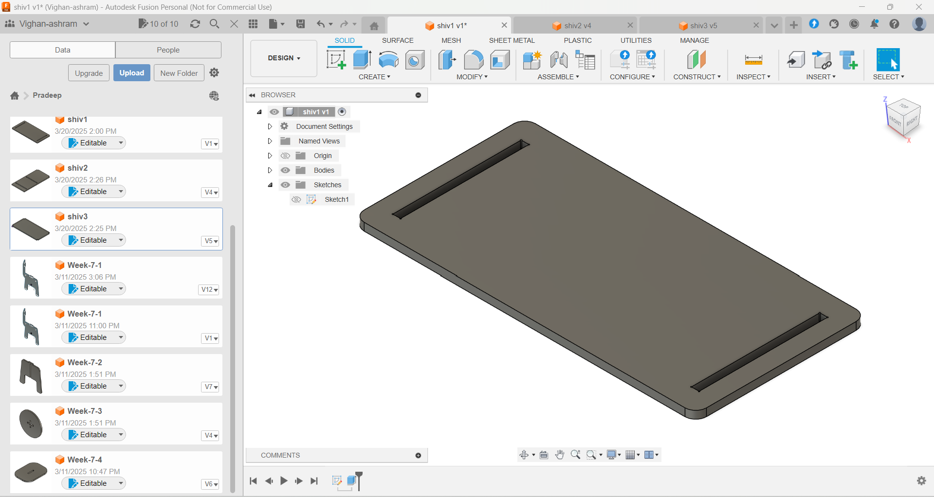
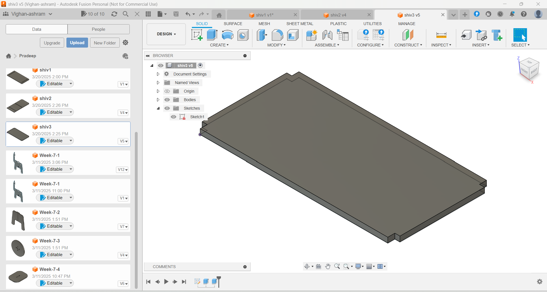
I used Fusion 360 for 3D design and created a Laptop table, which was designed in Three parts.
 |
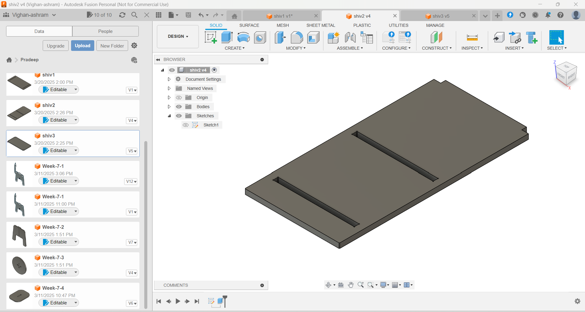 |
| Designing part 1 (Top Panel) |
Designing part 2 (Side Panel) |
 |
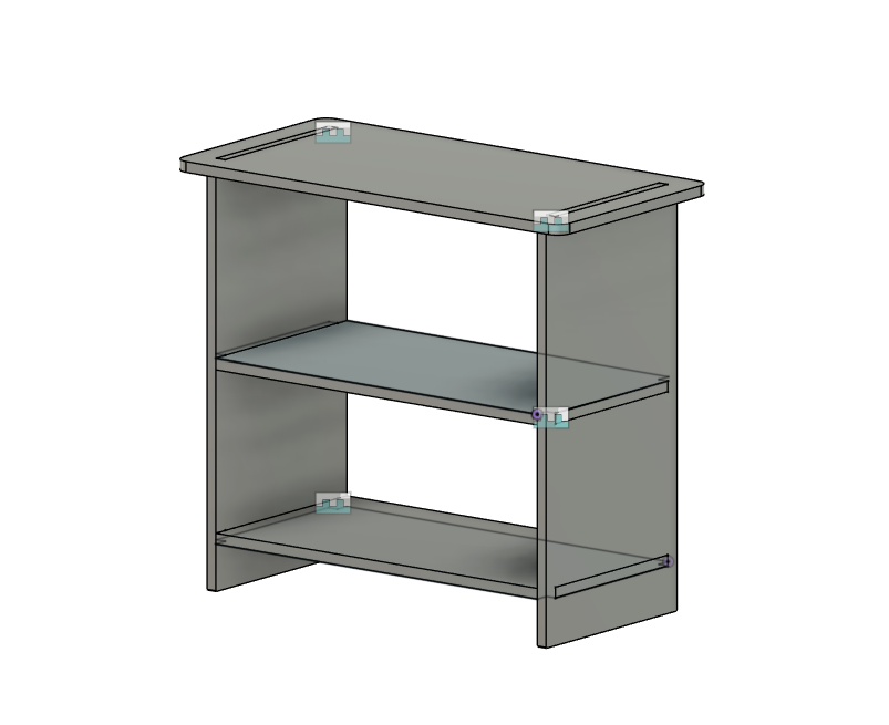 |
| Designing part 3 (Middle supporting Panel) |
Final design Assemblyed |
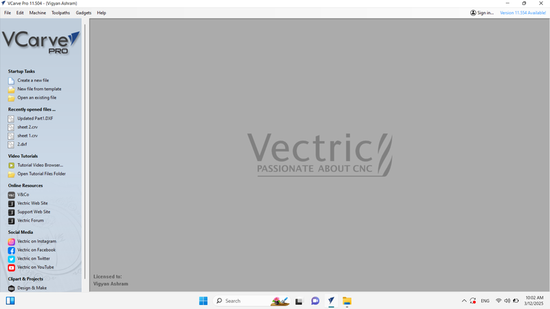
Using Carve Pro For tool path generateing
 |
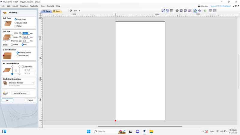 |
| First, Open "V Curve Pro" Then click on create new file. |
After clicking on 'Create New File,' a new workspace will open. Now, enter the plywood size according to your wood router. |
%20Assignment%207.png) |
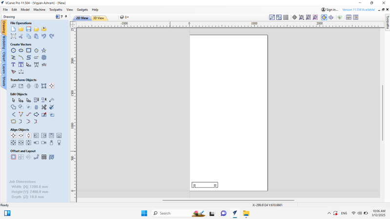 |
| After that, load the DXF file into the software. |
Once the DXF file is loaded, it will be added to the workspace. |
 |
 |
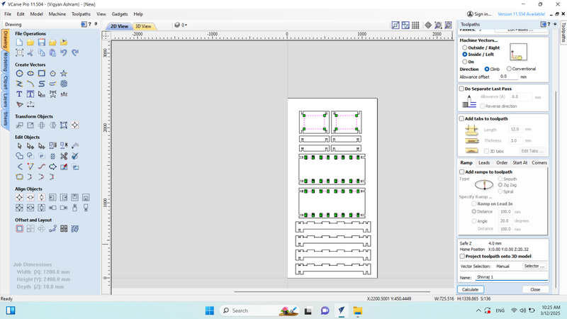
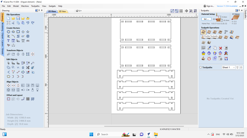
| After this, the inside cut was selected in the design. |
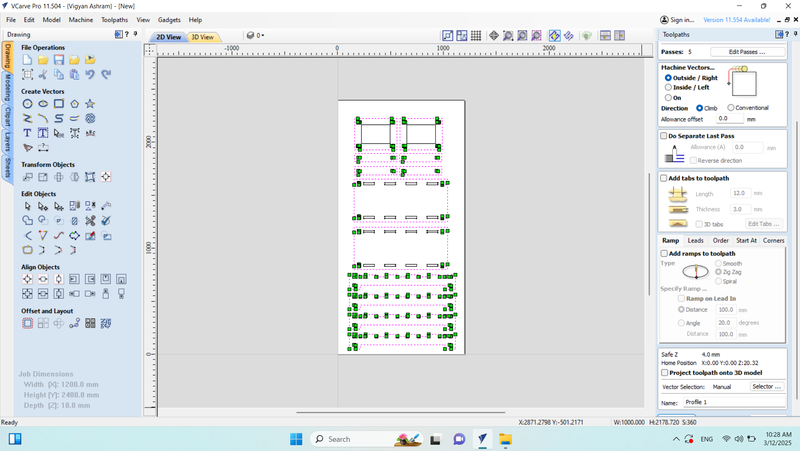
Then Out side cut selected. |
 |
 |
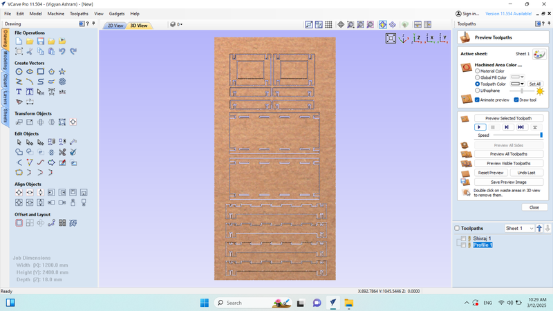
| Then, the design was simulated. |
After that, the final design was saved in CNC format. |
Starting the CNC Wood Router MAchine
%20Assignment%207.jpg) |
 |
| An 18mm plywood sheet was fixed in the wood router, and clamps were applied to ensure stability during cutting. |
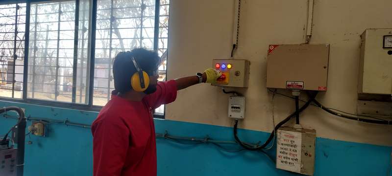
Then, the machine was powered on. This machine runs on a single-phase connection. |
 |
 |
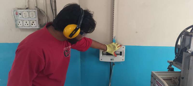
| The machine's main switch (MCB) was turned on. |
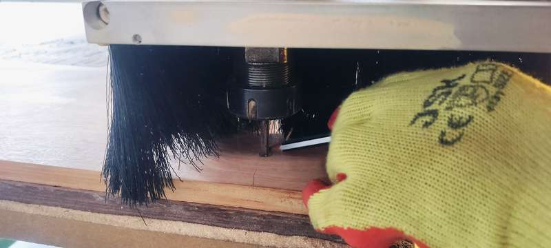
The machine's origin was set, and the end mill was marked with a pencil to ensure clarity on the exact origin position. |
Connecting Acorn software with the Router and loading CNC file
 |
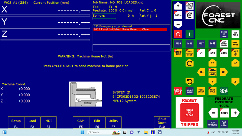 |
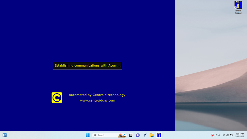
| Now, the machine was connected to the laptop using an RJ45 connector, and Acorn software was started. |
Then, Clicked to "Press to Clear" option for reset setting. |
 |
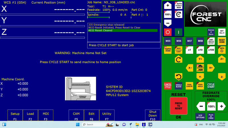 |
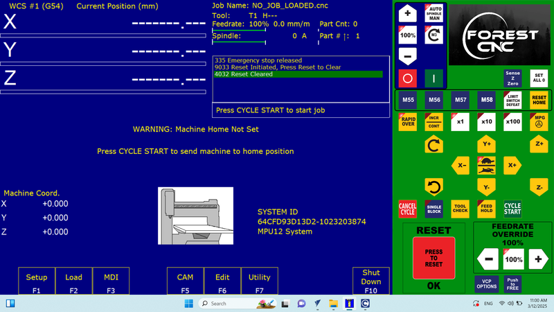
| Then, the reset settings were cleared, and the software displayed a "Reset Cleared" status. |
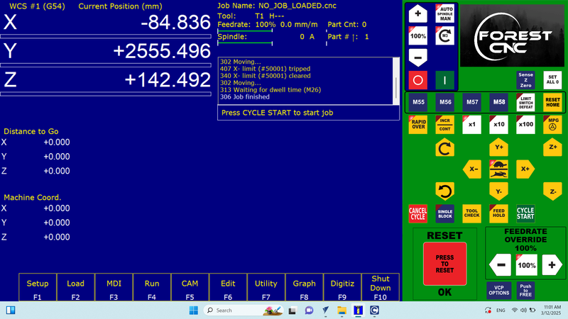
After this, I clicked on the "Reset Home" option. |
 |
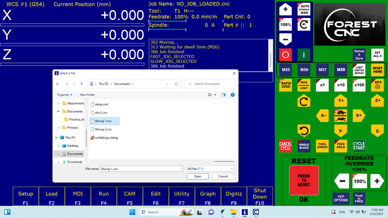 |
| Now, the software displayed the "Job Finished" status. |
After that, I loaded the CNC file into the software. |
 |
|
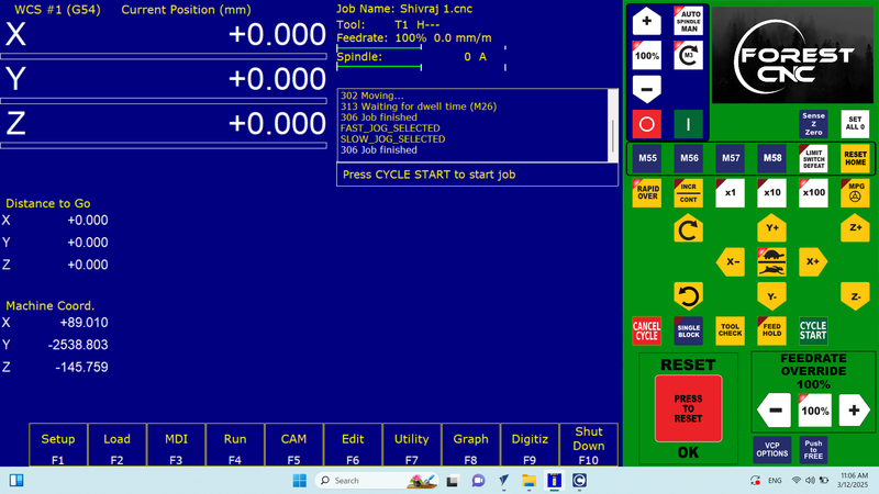
| After the file was loaded, it appeared in the software. Then, I clicked on the "Cycle Start" option to begin the design cutting process. |
|
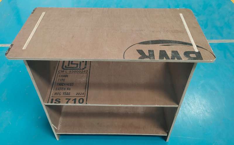
Final Design cutted and Assemblyed
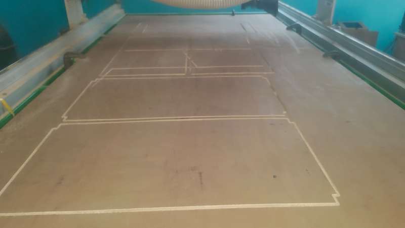 |
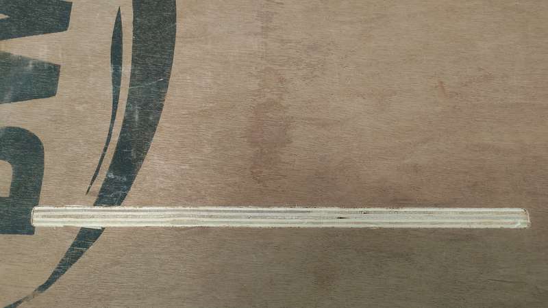 |
| Cutting with CNC Wood Router Complete |
Assembling Design |
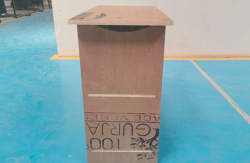 |
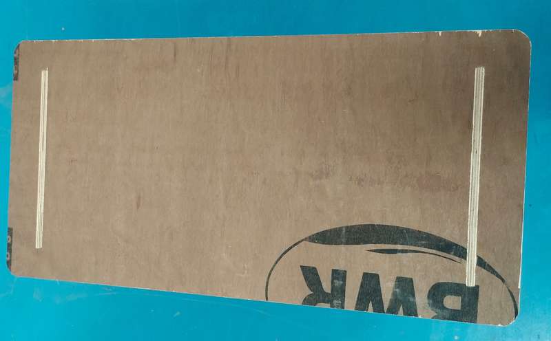 |
| Complete Assembling - Side View |
Top View |
 |
|
| Complete Design - Front View |
|
Original File Here
In DFX Formet
Top Part here
Side Part here
Middle Part here